Design of Readout Circuit with Quadrature Error and Auxiliary PLL for MEMS Vibratory Gyroscope


Abstract
1. Introduction
2. The MEMS Vibratory Gyro
3. Proposed Readout Circuit Architecture
4. Drive Mode Circuit
4.1. Low Noise TIA
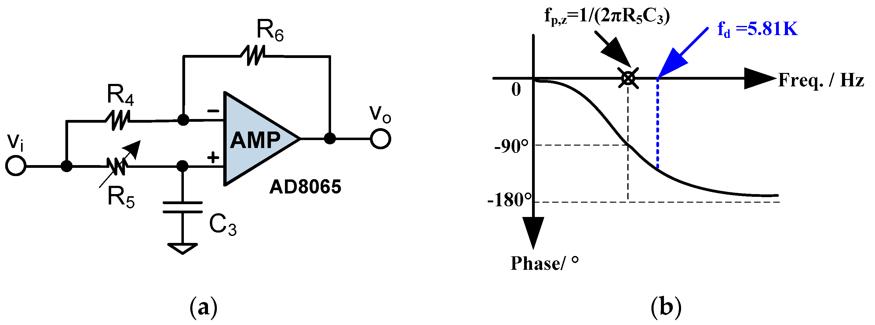
4.2. Phase Shifter
4.3. PLL
5. Sense Mode Circuit
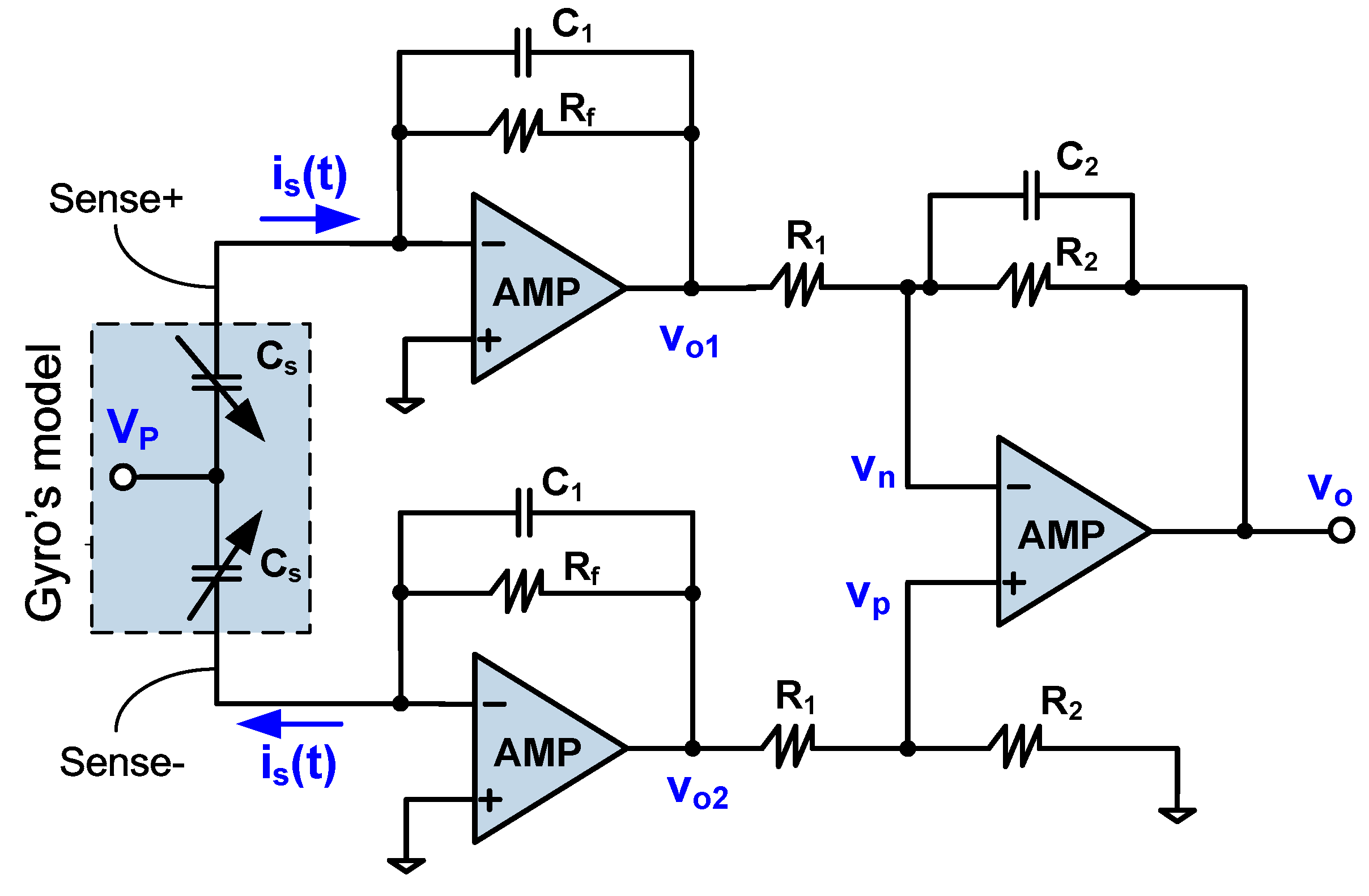
5.1. C/V Conversion Circuit
5.2. Coherent Demodulator
5.3. Low Pass Filter
6. Experimental Results
6.1. Function and Phase Alignment Measurement
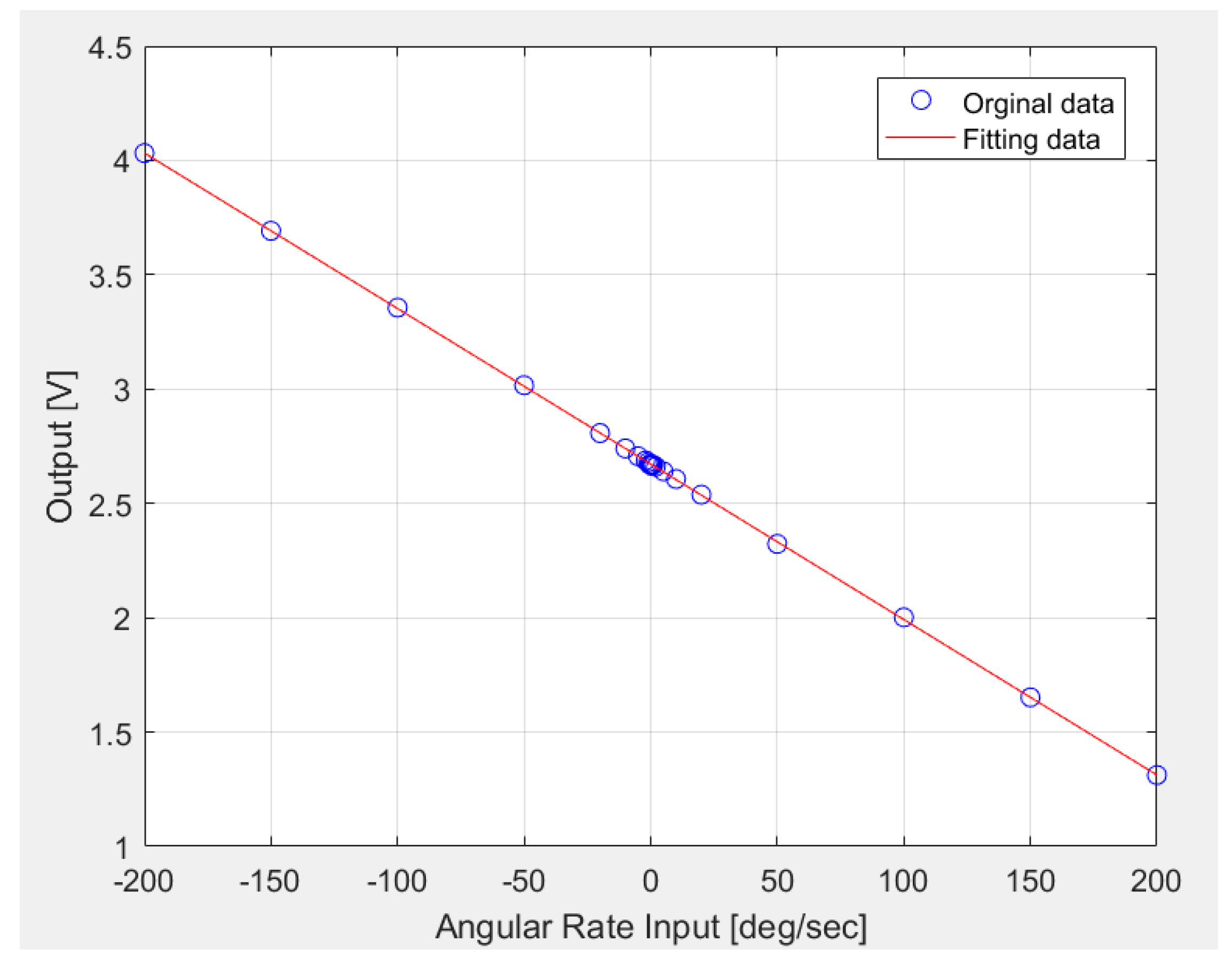
6.2. Scale Factor Measurement
6.3. Bias Instability Measurement
7. Conclusions
8. Patents
Author Contributions
Funding
Conflicts of Interest
References
- Yazdi, N.; Ayazi, F.; Najafi, K. Micromachined inertial sensors. Proc. IEEE 1998, 8, 1640–1659. [Google Scholar] [CrossRef]
- Shaeffer, D.K. MEMS inertial sensors: A tutorial overview. IEEE Commun. Mag. 2013, 51, 100–109. [Google Scholar] [CrossRef]
- Maeda, D.; Ono, K.; Giner, J.; Matsumoto, M.; Kanamaru, M.; Sekiguchi, T.; Hayashi, M. MEMS Gyroscope With Less Than 1-deg/h Bias Instability Variation in Temperature Range From −40 °C to 125 °C. IEEE Sens. J. 2018, 18, 1006–1015. [Google Scholar] [CrossRef]
- Yang, B.; Wu, L.; Lu, C.; Wang, G. A Digital Mode-Matching Control System Based on Feedback Calibration for a MEMS Gyroscope. J. Sens. 2019, 2019, 1–19. [Google Scholar] [CrossRef]
- Marx, M.; Cuignet, X.; Nessler, S.; De Dorigo, D.; Manoli, Y. An Automatic MEMS Gyroscope Mode Matching Circuit Based on Noise Observation. IEEE Trans. Circuits Syst. Express Briefs 2019, 66, 743–747. [Google Scholar] [CrossRef]
- Gu, H.; Su, W.; Zhao, B.; Zhou, H.; Liu, X. A Design Methodology of Digital Control System for MEMS Gyroscope Based on Multi-Objective Parameter Optimization. Micromachines 2020, 11, 75. [Google Scholar] [CrossRef]
- Cao, H.; Xue, R.; Cai, Q.; Gao, J.; Zhao, R.; Shi, Y.; Shen, C. Design and Experiment for Dual-Mass MEMS Gyroscope Sensing Closed-Loop System. IEEE Access 2020, 8, 48074–48087. [Google Scholar] [CrossRef]
- Li, Q.; Xiao, D.; Zhou, X.; Xu, Y.; Zhuo, M.; Hou, Z.; Wu, X. 0.04 degree-per-hour MEMS disk resonator gyroscope with high-quality factor (510 k) and long decaying time constant (74.9 s). Microsyst. Nanoeng. 2018, 4, 1–11. [Google Scholar] [CrossRef]
- Sheng, B.; Chen, F.; Qian, C.; Xu, D.; Guo, S.; Li, X. Design of a Dual Quantization Electromechanical Sigma–Delta Modulator MEMS Vibratory Wheel Gyroscope. IEEE/ASME J. Microelectromech. Syst. 2018, 27, 218–230. [Google Scholar] [CrossRef]
- Bu, F.; Guo, S.; Cheng, M.; Zheng, F.; Xu, D.; Zhao, H. Effect of circuit phase delay on bias stability of MEMS gyroscope under force rebalance detection and self-compensation method. J. Micromech. Microeng. 2019, 29, 095002. [Google Scholar] [CrossRef]
- Wang, Y.; Fu, Q.; Zhang, Y.; Zhang, W.; Chen, D.; Yin, L.; Liu, X. A Digital Closed-Loop Sense MEMS Disk Resonator Gyroscope Circuit Design Based on Integrated Analog Front-end. Sensors 2020, 20, 687. [Google Scholar] [CrossRef] [PubMed]
- Xu, Y.; Li, Q.; Zhang, Y.; Zhou, X.; Wu, X.; Xiao, D. Honeycomb-Like Disk Resonator Gyroscope. IEEE Sensors J. 2020, 20, 85–94. [Google Scholar] [CrossRef]
- Hedenstierna, N.; Habibi, S.; Nilsen, S.; Kvisteroy, T.; Jensen, G. Bulk micromachined angular rate sensor based on the ‘butterfly’-gyro structure. In Proceedings of the Technical Digest. MEMS 2001. 14th IEEE International Conference on Micro Electro Mechanical Systems (Cat. No.01CH37090), Interlaken, Switzerland, 25 January 2001; pp. 178–181. [Google Scholar] [CrossRef]
- Lapadatu, D.; Blixhavn, B.; Holm, R.; Kvisteroy, T. SAR500-A high-precision high-stability butterfly gyroscope with north seeking capability. In Proceedings of the IEEE/ION Position, Location and Navigation Symposium, Indian Wells, CA, USA, 4–6 May 2010; pp. 6–13. [Google Scholar] [CrossRef]
- Su, J.; Xiao, D.; Wang, X.; Chen, Z.; Wu, X. Vibration sensitivity analysis of the ‘Butterfly-gyro’ structure. Microsyst. Technol. 2013, 20, 1281–1290. [Google Scholar] [CrossRef]
- Xu, X.; Xiao, D.; Li, W.; Xu, Q.; Hou, Z.; Wu, X. A Dual-Butterfly Structure Gyroscope. Sensors 2017, 17, 2870. [Google Scholar] [CrossRef]
- Miao, T.; Ou, F.; Xu, Q.; Hou, Z.; Wu, X.; Xiao, D. A novel method of quadrature compensation in the butterfly resonator based on modal stiffness analysis. AIP Adv. 2018, 8, 105025. [Google Scholar] [CrossRef]
- Qiang, X.; Xiao, D.; Zhanqiang, H.; Ming, Z.; Wenyin, L.; Xiangming, X.; Xuezhong, W. A Novel High-Sensitivity Butterfly Gyroscope Driven by Horizontal Driving Force. IEEE Sens. J. 2018, 19, 2064–2071. [Google Scholar] [CrossRef]
- Khan, N.; Ahamed, M.J. Design and development of a MEMS butterfly resonator using synchronizing beam and out of plane actuation. Microsyst. Technol. 2019, 26, 1643–1652. [Google Scholar] [CrossRef]
- Acar, C.; Shkel, A. MEMS Vibratory Gyroscopes; Springer Science and Business Media: Berlin, Germany, 2009. [Google Scholar]
- Geen, J.A.; Carow, D.W. Micromachined gyros. US Patent 6122961, 26 September 2000. [Google Scholar]
- Geen, J.; Sherman, S.; Chang, J.; Lewis, S. Single-chip surface micromachined integrated gyroscope with 50°/h Allan deviation. IEEE J. Solid-State Circuits 2002, 37, 1860–1866. [Google Scholar] [CrossRef]
- Geen, J.A. Micromachined sensors with quadrature suppression. US Patent 7032451, 25 April 2006. [Google Scholar]
- Saukoski, M.; Aaltonen, L.; Halonen, K.A.I. Zero-Rate Output and Quadrature Compensation in Vibratory MEMS Gyroscopes. IEEE Sensors J. 2007, 7, 1639–1652. [Google Scholar] [CrossRef]
- Tatar, E.; Alper, S.E.; Akin, T. Quadrature-Error Compensation and Corresponding Effects on the Performance of Fully Decoupled MEMS Gyroscopes. J. Microelectromech. Syst. 2012, 21, 656–667. [Google Scholar] [CrossRef]
- Tan, Z.; Nguyen, K.; Yan, J.; Samuels, H.; Keating, S.; Crocker, P.; Clark, B. A dual-axis MEMS vibratory gyroscope ASIC with 0.0061°/s/VHz noise floor over 480 Hz bandwidth. In Proceedings of the 2017 IEEE Asian Solid-State Circuits Conference (A-SSCC), Seoul, South Korea, 6–8 November 2017; pp. 21–24. [Google Scholar] [CrossRef]
- Antonello, R.; Oboe, R.; Prandi, L.; Caminada, C.; Biganzoli, F. Open loop compensation of the quadrature error in MEMS vibrating gyroscopes. In Proceedings of the 2009 35th Annual Conference of IEEE Industrial Electronics, Porto, Portugal, 3–5 November 2009; pp. 4034–4039. [Google Scholar] [CrossRef]
- Seeger, J.; Lim, M.; Nasiri, S. Development of high-performance, high-volume consumer mems gyroscopes. In Proceedings of the 2010 Solid-State, Actuators, and Microsystems Workshop Technical Digest, Hilton Head Island, SC, USA, 6–10 June 2010; pp. 61–64. [Google Scholar] [CrossRef]
- Omar, A.; Elshennawy, A.; Abdelazim, M.; Ismail, A.H. Analyzing the Impact of Phase Errors in Quadrature Cancellation Techniques for MEMS Capacitive Gyroscopes. In Proceedings of the 2018 IEEE Sensors Applications Symposium (SAS), New Delhi, India, 28–31 October 2018; pp. 1–4. [Google Scholar] [CrossRef]
- Sharma, A.; Zaman, M.F.; Ayazi, F. A Sub-0.2∘/hr Bias Drift Micromechanical Silicon Gyroscope With Automatic CMOS Mode-Matching. IEEE J. Solid-State Circuits 2009, 44, 1593–1608. [Google Scholar] [CrossRef]
- Norouzpour-Shirazi, A.; Zaman, M.F.; Ayazi, F. A Digital Phase Demodulation Technique for Resonant MEMS Gyroscopes. IEEE Sens. J. 2014, 14, 3260–3266. [Google Scholar] [CrossRef]
- Zhong, W.; Han, G.; Si, C.; Ning, J.; Yang, F. Fabrication and characterization of an SOI MEMS gyroscope. J. Semicond. 2013, 34, 64004. [Google Scholar] [CrossRef]
- Song, J.W.; Song, H.-M.; Lee, Y.J.; Park, C.G.; Sung, S. Design of Oscillation Control Loop withCoarse-Precision Mode Transition for Solid-State Resonant Gyroscope. IEEE Sens. J. 2015, 16, 1730–1742. [Google Scholar] [CrossRef]
- ADI, USA, LTC1565 Datasheet. (2000). Available online: https://www.analog.com/cn/products (accessed on 15 June 2020).
- New Japan Radio, Japan: NJM567 Datasheet. (2012). Available online: https://www.njr.com/electronic_device (accessed on 15 June 2020).
- ADI, USA: AD8065 Datasheet. (2008). Available online: http://www.analog.com.cn/product (accessed on 15 June 2020).
- Texas Instruments, USA: OPA656. (2008). Available online: http://www.ti.com.cn/product (accessed on 15 June 2020).
- ADI, USA: AD835 Datasheet. (2008). Available online: http://www.analog.com.cn/product (accessed on 15 June 2020).
- Butterworth, S. On the Theory of Filter Amplifier. Wirel. Eng. 1930, 7, 536–541. [Google Scholar]
- Kugelstadt, T. Active Filter Design Techniques. In Op Amps for Everyone, 3rd ed.; Elsevier: Amsterdam, The Netherlands, 2008. [Google Scholar]
- Sharma, A. CMOS systems and circuits for sub-degree per hour MEMS gyroscopes. Ph.D. Thesis, Georgia Institute of Technology, Atlanta, GA, USA, 2007. [Google Scholar]
- Leeson, D.B. A simple model of feedback oscillator noise spectrum. Proc. IEEE 1966, 54, 329–330. [Google Scholar] [CrossRef]


| Parameters | Values |
|---|---|
| Drive-mode resonant frequency | 5.817 KHz |
| Drive-mode Q value | 35,000 |
| Sense-mode resonant frequency | 6.05 KHz |
| Sense-mode Q value | 500 |
| Vacuum level | 100 mTorr |
| Work mode | Mode splits |
| DC polarization voltage | 5–10 V |
| Quadrature error ratio | 0.22 |
© 2020 by the authors. Licensee MDPI, Basel, Switzerland. This article is an open access article distributed under the terms and conditions of the Creative Commons Attribution (CC BY) license (http://creativecommons.org/licenses/by/4.0/).
Share and Cite
Chen, H.; Zhong, Y. Design of Readout Circuit with Quadrature Error and Auxiliary PLL for MEMS Vibratory Gyroscope. Sensors 2020, 20, 4564. https://doi.org/10.3390/s20164564
Chen H, Zhong Y. Design of Readout Circuit with Quadrature Error and Auxiliary PLL for MEMS Vibratory Gyroscope. Sensors. 2020; 20(16):4564. https://doi.org/10.3390/s20164564
Chicago/Turabian StyleChen, Hua, and Yanqing Zhong. 2020. "Design of Readout Circuit with Quadrature Error and Auxiliary PLL for MEMS Vibratory Gyroscope" Sensors 20, no. 16: 4564. https://doi.org/10.3390/s20164564
APA StyleChen, H., & Zhong, Y. (2020). Design of Readout Circuit with Quadrature Error and Auxiliary PLL for MEMS Vibratory Gyroscope. Sensors, 20(16), 4564. https://doi.org/10.3390/s20164564