Review

A Review of Acoustic Impedance Matching Techniques for Piezoelectric Sensors and Transducers

Department of Electrical and Computer Engineering, Michigan State University, East Lansing, MI 48824, USA
Sensors 2020, 20(14), 4051; https://doi.org/10.3390/s20144051
Submission received: 17 May 2020 / Revised: 6 July 2020 / Accepted: 16 July 2020 / Published: 21 July 2020
(This article belongs to the Section Electronic Sensors)

Abstract

:
The coupling of waves between the piezoelectric generators, detectors, and propagating media is challenging due to mismatch in the acoustic properties. The mismatch leads to the reverberation of waves within the transducer, heating, low signal-to-noise ratio, and signal distortion. Acoustic impedance matching increases the coupling largely. This article presents standard methods to match the acoustic impedance of the piezoelectric sensors, actuators, and transducers with the surrounding wave propagation media. Acoustic matching methods utilizing active and passive materials have been discussed. Special materials such as nanocomposites, metamaterials, and metasurfaces as emerging materials have been presented. Emphasis is placed throughout the article to differentiate the difference between electric and acoustic impedance matching and the relation between the two. Comparison of various techniques is made with the discussion on capabilities, advantages, and disadvantages. Acoustic impedance matching for specific and uncommon applications has also been covered.

1. Introduction

Piezoelectric materials serve with a wide variety of applications when used in many ways. As bulk materials, they fulfill the purpose of actuation and sensing in macro and large devices. Some applications of bulk piezoelectric materials are biomedical ultrasound [1,2,3], piezoelectric–catalysis-based environmental remediation [4], structural control [5,6,7], vibration control [8,9], vibration sensing [10,11], and structural health monitoring [12,13,14]. As thin films ranging from few micrometers to nanometers, they have seen growing use in applications such as force microscopy [15], nano-positioning [16], micromechanical systems (MEMS) [17,18,19] and nanoelectromechanical systems (NEMS) [20,21], energy harvesters [22,23], etc. Some well-known applications of thin films are MEMS microphone [24], headphone [24], loudspeaker [24,25,26], acoustic emission sensor [27,28], vibration sensor [10,14], inertial sensor [19], tactile sensors [29,30,31], power harvesting [32,33], ultrasound transducers [34,35,36,37,38], and guided wave sensors [39,40,41]. Thin films are preferably made of nontoxic piezopolymers or piezocomposites. From the past two decades, major improvements in the piezoelectric material properties and manufacturing techniques have reduced the manufacturing cost [42,43,44,45,46,47]. The low cost and excellent properties have led to the surge in their use as materials for the internet of things (IOT) applications [48,49]. The above-mentioned applications involve the operation at quasi-static, infrasonic, audio, and ultrasonic frequencies [50]. The development of high-frequency ultrasonic imaging has pushed the limits of these technologies, resulting in diagnostic capability with microscopic information of living tissue involving eye, skin, and vascular muscles [51,52]. Therefore, piezoelectric materials are used most widely in biomedical applications [53] such as ultrasonography [54,55,56,57,58,59,60,61,62], due to the ability to produce real-time high resolution 3D images of biological tissue, eliminating the need for hazardous X-rays. Special applications such as scanning acoustic microscopy, cellular stimulation, and particle manipulation are the results of very high-frequency ultrasound 100 MHz [63,64,65,66].
The efficient performance of piezoelectric devices depends on the proper matching of electric and acoustic impedances, especially when considered in their design stages. With a rising development of piezoelectric devices, there is a need for versatile tools to assist with the electric and acoustic impedance matching, especially on a common platform. However, the requirement of broad interdisciplinary knowledge from a variety of disciplines such as acoustics, vibration, electrical, electronics, signal processing, imaging, anatomy, physiology, materials, etc., has made the design procedures available so far mostly empirical. The design and manufacturing procedures of highly efficient transducers and sensors remain with most manufacturers as trade secrets of the highest order [67]. A word of caution is needless to distinguish electric impedance from mechanical or acoustic impedance, since these two serve different purposes but are dependent on each other. Figure 1 shows a schematic of a pitch–catch and pulse–echo system with details of the transducer with acoustic impedance matching layers and its associated electronics.
Figure 2 shows the process flow of electric and acoustic impedance matching while designing a piezoelectric transducer system. Electric impedance matching enables an efficient transfer of electric power whereas acoustic matching enables the proper transfer of acoustic energy. Electrical impedance matching involves the design of the electric matching circuit that connects the driving or receiving circuit to the transducer. It also involves the design of the geometry and electric property of the cable and transducer. Acoustic impedance matching involves the selection of materials and geometric design of the matching layer, backing layer, and the piezoelectric element. The passive matching techniques involves the matching of acoustic passive layers with the piezoelectric element, whereas the active matching technique involves the modification of piezoelectric element properties, eliminating the need for matching layers. A change of geometry during acoustic matching may change the electric property, which leads to redesigning of the electric impedance matching network. Thus, both electric and acoustic impedance matching involves the transducer design considerations in common, especially the piezoelectric element, which is directly related. Thus, highly optimized design can only result when both electric and acoustic impedance matching are considered together. Such an optimized design is possible using commercial software and an iterative design procedure.
Often, the transducer and driving/receiver circuit available commercially have fixed specifications, which cannot be altered. In addition, components available commercially for the design of electric impedance matching circuit are difficult to know before the design of the transducer. Thus, for the most uncommon uses in the laboratory, limited uses in industries, and for special applications, the transducer is designed first followed by its electric impedance matching with source and receiver [68]. The acoustic impedance matching of a transducer involves the matching of piezoelectric element properties with the media in which the acoustic signal is being transmitted. The design is carried out for a given operating frequency or for a given frequency range with possible information of wave propagation media (air, water, biological tissue etc.) and operating environment (temperature, corrosion, radiation etc.) [69].
High-performance transducers involve a design process where choosing active materials with high electromechanical coupling factor is one of the easiest ways. Another option is an improvement in the acoustic design including both matching layers and the backing. Apart from acoustic matching, the backing material is designed to achieve proper isolation to minimize reflection within the piezoelectric element and transducer casing, as shown in Figure 1. Based on the processing method and poling direction, the acoustic and piezoelectric properties of the piezoelectric materials can differ, which has to be considered while designing the acoustic impedance matching layers. In addition, there are limitations on the way of using the piezoelectric material depending upon the polarization direction, anisotropy of elastic constants, and electrical and thermal considerations. In highly efficient designs especially for the pitch–catch type of operation, the exciter (actuator) and receiver (sensor) are designed with a different type of piezoelectric elements for which different matching layers and backing material are needed. In advanced transducer designs, the material properties of the piezoelectric element are modified to assist with the acoustic impedance matching. The transducer design process is complicated due to various factors influencing the design ranging from application needs to the limitations posed by the availability of material and hardware components for fabrication. Thus, a common tool is unavailable to design acoustic and electric impedance matching for the transducer system together.
A detailed review of electric impedance matching techniques for piezoelectric materials used in the configuration of sensors, actuators, and transducers has been provided in Ref. [70]. In this paper, the focus has been laid on the acoustic impedance matching techniques for piezoelectric devices. Depending on the requirements of an application and limitations arising due to the design constraints of the electric and acoustic elements of the transducer system, the acoustic impedance matching procedure may be dependent or independent. The independent design involves the matching of acoustic impedance of piezoelectric element(s) to the wave propagating medium. The dependent procedure involves iterative process or trials where the matching layers are redesigned to achieve optimal performance for varying the acoustic and electric configuration of the piezoelectric element [71]. Each iteration of the dependent procedure is like an independent procedure. Many techniques have been reported so far to match the acoustic impedance of piezoelectric element with the wave propagating medium. These techniques involve changing the geometry or material property of the matching layer or the piezoelectric element itself (for example, piezocomposites with varying filler or fiber content).
Section 1 provides a brief review of common piezoelectric and acoustic matching layer materials used for acoustic impedance matching. Section 2 presents the available tools to assist in the various stages of acoustic impedance matching. Special materials that are different from the conventional materials developed for acoustic impedance matching have been discussed in Section 3. Section 4 discusses the acoustic impedance matching techniques developed for specific types of transducers. Section 5 discusses the acoustic impedance matching techniques that consider requirements arising from specific applications. Section 6 presents the concluding remarks.

1.1. Theory of Piezoelectricity and Vibration Modes

Most of the transducers used in biomedical, nondestructive evaluation (NDE), and structural health monitoring (SHM) applications operate based on the principle of piezoelectricity. Piezoelectricity is a phenomenon where an electrical charge is generated under the application of mechanical stress or vice versa. The elastic and electrical properties in piezoelectric materials are coupled. Therefore, mechanical parameters such as stress σ and strain ε , and the electrical parameters such as electric field E and dielectric displacement D are related by constitutive relations [72]. For an unstressed non-piezoelectric medium, the electrical relation is given by
D m = ϵ m n E n   ,
where ϵ m n is the stress-free permittivity matrix of the piezoelectric medium. The stress-free permittivity of piezoelectric material is obtained by measuring it with stress-free boundary conditions. At zero electric field, the mechanical relation for the same medium is given by
ε i j = S i j k l σ k l   ,
where S i j k l is the tensor representing the short-circuit mechanical compliances of the medium. The elements of S i j k l are measured using the strain developed for the applied stress with the electrodes of the piezoelectric material being shorted. The shorting of electrodes results in the electrical boundary conditions with zero field across faces but allows the charge to flow from the positive to the negative terminal. Thus, shorting prevents any effect on compliance measurement due to piezoelectricity. The interaction of electrical and mechanical variables in a linear regime is described by the constitutive relations given by
D m = d m k l σ k l + ϵ m n E n
ε i j = S i j k l σ k l + d n i j E n   ,
where d i j n is a tensor of the piezoelectric material. Equation (3) is called the sensing law, which describes the direct piezoelectric effect and is used to estimate the total charge and thereby the voltage developed by the receiver or sensor or transducer in a sensing configuration. Equation (4) is called the actuation law; it describes the converse piezoelectric effect and is used to estimate the stress and thereby the force developed by an exciter, actuator, or transducer in an actuating configuration. Depending upon the piezoelectric material geometry and poling direction, the above Equations (3) and (4) are applied to determine the outcome parameters such as force or voltage. These parameters are further related to material properties in various ways depending on the modes of operation and application. Therefore, these performance parameters are many and have been reported by researchers and engineers to assist in the design of transducers and their acoustic matching layers. These parameters will be further discussed in this section. Figure 3 shows the commonly used shapes of piezoelectric materials and their vibration modes. Here, poling is along axis 3. Polarization destroys the isotropy in the direction of poling and retains it in any other direction perpendicular to it (i.e., directions along axes 1 and 2). The set of independent piezoelectric and dielectric constants for this symmetry are d 31 , d 33 , d 15 , ϵ 11 and ϵ 33 . The d 33 coefficient describes the electric polarization generated in the same direction as the stress applied and is called the longitudinal coefficient [72]. The d 31 coefficient describes the electric polarization generated in a direction perpendicular to the direction of the applied stress and is called the transverse coefficient [11,72]. The property d 33 is a commonly used property in biomedical ultrasound, NDE probes, vibration control, and energy harvesting applications. The property d 31 is utilized by SHM, energy harvesting, vibration control, monitoring, etc [11,40,41,73]. The d 15 shear piezoelectric coefficient describes the polarization generated, which is inclined to the direction of applied stress [74].
Although a piezoelectric material can exhibit many piezoelectric coefficients and have many properties, they are selected depending on the desired vibration mode and operating modes. Consider an example for the vibrational mode with a predominant involvement of the thickness. For an application where the thickness or out-of-plane vibration measurement is desired, the piezoelectric element with greater d 33 property is selected, with d 31 and d 15 being ignored.

1.2. Piezoelectric Operating Modes and Sensitivity

Possible operating modes are pitch–catch (acts either as sensor or actuator) and pulse–echo (acts as both sensor and actuator). An important property of a sensor is the sensitivity g . t , which is the open circuit charge developed due to applied stress, where t is the thickness of the piezoelectric element. The coefficient g is related to the piezoelectric coefficient d by the relation g = d / ( ϵ r ϵ 0 ) , where ϵ r is the relative permittivity of the piezoelectric element and ϵ 0 is the permittivity of free space. This relation is a coefficient realized from Equation (3) by ignoring the indices and noting that the external field E n is zero and D = ϵ E , where ϵ = ϵ r ϵ 0 and E is the generated electric field. This sensing condition yields E = g σ , relating applied stress to the electric field generated across the piezoelectric element. In hydrophone applications, properties such as d 33 and d 31 are taken into account due to equal stress from all directions in the piezoelectric element by the figure of merit (FOM) relation d h g h , where d h = d 33 + 2 d 31 and g h = g 33 + 2 g 31 . The piezoelectric charge coefficient d i j characterizes transmission capability, whereas the piezoelectric voltage coefficient g i j implies reception capability. Both coefficients are to be maximized when the same transducer is used for transmission and reception (for example, the pulse–echo measurement technique). In low-intensity ultrasound applications, g 33 is given more importance. A large dielectric constant ϵ with relative permittivity of ϵ r ~100 plays an important role in electric impedance matching between the transducer and the driving/reception electronics by maximizing the voltage coefficient. Dielectric losses can be considered by relation d h g h / tan δ . Substantial acoustic energy is dissipated if the dielectric loss factor tan δ is not minimized [53]. Another property related to losses is the mechanical quality factor Q m , which is the amount of mechanical loss due to internal friction or acoustic viscosity. It is desirable for the Q m to be minimum, but in some cases where the generation of short acoustic pulse is required, a compromise is selected Q m = 2–10 to avoid ringing [76].
The electromechanical coupling factor k is another important property in piezoelectric materials that indicates the effectiveness of conversion of electrical energy to mechanical energy and vice versa. The following are the common coupling factors of piezoelectric ceramics [77,78] that are defined as
k 15 = d 15 S 44 ϵ 11
k 33 = d 33 S 33 ϵ 33
k 31 = d 31 S 11 ϵ 33   ,
where subscripts 4 and 5 refer to planes normal to the 1 and 2 axes, respectively. For the thickness mode transducer, the thickness coupling coefficient k 33 should be high with low planar mode coupling k 31 . The electromechanical coupling factors depend on all the properties required for both sensors as well as actuators such as elastic, piezoelectric, and dielectric properties. Therefore, the electromechanical coupling factor is a good measure of transducer properties of a piezoelectric material operating in pulse–echo mode or pitch–catch (both transmit and receive) mode. The lead zirconate titanate (PZT)-4 material is widely used as an ultrasonic transducer material. The properties of commonly used piezoelectric ceramics and polymers are discussed next.

1.3. Commonly Used Piezoelectric Materials as an Active Matching Layer

Material properties greatly influence the performance of piezoelectric devices operating especially at high frequencies. The advent of composites and nanocomposites gave tremendous material combinations to design transducers with a good piezoelectric element and its associated matching layer. Sometimes, piezoelectric material properties are altered to match directly with the propagating media. In such cases, the matched piezoelectric materials are called an active matching layer. This eliminates the requirement of a passive matching layer. A slight altering of piezoelectric materials can facilitate the material selection and design of a passive acoustic matching layer. Therefore, piezoelectric material properties have been very crucial in the optimal design of transducers along with their acoustic matching layers, which this paper summarizes in greater detail. Piezoceramic wafers, piezopolymer films, and piezocomposite materials are commonly used as an active element of sensors, actuators, energy harvesters, and transducers. The electric, mechanical, and acoustic properties differ for bulk and thin-film piezoelectric materials. While bulk materials have been standardized where many different manufacturers report similar properties, thin-film materials differ drastically in the preparation procedure, as the control parameters involved in their processing are many. Therefore, they are not standardized, and it is difficult to list the properties for thin-film sensors. The common bulk piezoelectric materials are listed in Table 1. Piezoelectric substances can be broadly classified as natural materials and synthetic materials. Naturally occurring piezoelectric materials are quartz SiO2, berlinite, sucrose, Rochelle salt NaKC4H4O6.4H2O, topaz, and a tourmaline group of minerals. Synthetic piezoelectric materials are further classified as synthetic crystals, ceramics, and polymers. Synthetic piezoelectric crystals are gallium orthophosphate (GaPO4) and langasite (La3Ga5SiO14) [79]. Synthetic piezoelectric ceramics are barium titanate (BaTiO3), lead titanate (PbTiO3), lead zirconate titanate (Pb[ZrxTi1−x]O3 0 ≤ x ≤ 1), potassium niobate (KNbO3), lithium niobate (LiNbO3), lithium tantalate (LiTaO3), sodium tungstate (NaWO3), zinc oxide (ZnO), aluminium nitride (AlN), scandium–aluminum nitride [80], etc. Synthetic piezoelectric polymers are materials such as polyvinylidene fluoride (PVDF) and copolymers of vinylidene fluoride (VDF) with trifluoroethylene (TrFE), or with tetrafluroethylene (TeFE) [10,11,81]. The common bulk piezoelectric materials, their processing techniques, and the resulting acoustic and electric properties needed for acoustic impedance matching are explained next.

1.3.1. Piezoelectric Ceramics

The bulk piezoceramic is prepared by high-temperature sintering at 600–700 °C [82] yielding high density and non-piezoelectric ceramics that constitute ferroelectric crystallites with random orientation. These non-piezoelectric ceramics are made piezoelectric by poling treatment in a chosen direction to align the electric dipoles. Poling is done under a realizable high electric field typically below the breakdown field 2–5 kV/mm and below the ferroelectric Curie point at 80–150 °C [83]. This poling direction governs the vibration modes shown in Figure 3. To influence the domain structure for the enhancement of piezoelectricity, the poled ceramics are cooled through the Curie temperature. The electroding is done by depositing metals such as gold, silver, chromium, or nickel.
Out of the available piezoceramic materials, lead zirconate titanate PZT (Pb[ZrxTi1−x]O3) (PZT) founded by Jaffe et al. [84] is most widely used because of its strong and stable piezoelectric characteristics, high strength, high Curie point (temperature above which they are non-polar), and ease of fabrication [77]. Most piezoelectric ceramics are based on nominal composition 52–54 mol% lead zirconate and 46–48 mol% lead titanate, which is called PZT. This composition is doped with different elements by different manufacturers with proprietary formulas for different compositions. Some commonly used compositions are PZT-5 with Nb-doping, PZT-6 with Cr-doping, PZT-7 with La-doping, and PZT-4 with Fe-doping. The properties of these piezoelectric ceramics commonly employed by transducer designers can be found in Ref [77,85] and have been listed in Table 1.
Most PZT ceramics are characterized by high elastic moduli, high dielectric constant, low elastic and dielectric loss and high electromechanical coupling factor. However, during processing stages such as calcination and sintering, lead oxide vaporizes in environment accumulating in organisms and causing damage to the nervous system. Also, these are potentially toxic during manufacturing, use and mainly disposal [86]. Thus, lead-free piezoelectric materials such as Barium Titanate (BaTiO3), Lithium Niobate (LiNbO3), Sodium Bismuth Titanate (Na0.5Bi0.5TiO3), Potassium Bismuth Titanate (K0.5Bi0.5TiO3), Potassium Sodium Diniobate (K0.5Na0.5NbO6), Bismuth Ferrite (BiFeO3) whose properties are comparable to that of PZT have attracted lots of attention [87,88,89]. The overall piezoelectric properties of lead-free materials such as barium titanate, lithium niobate and potassium sodium diniobate are slightly lower [90] when compared with PZT materials as seen in Table 1. The natural materials such as quartz and Rochelle salt have very lower piezoelectric properties when compared to synthetic materials [85]. Therefore, synthetic materials are preferred for transducer applications unless other acoustic properties outweigh the electric properties for some applications.
Due to the inherent brittle nature of piezoelectric ceramics and piezoelectric crystals, piezoceramic thin films [91,92] and coatings [93,94] are being explored. High-frequency imaging (>20 MHz), micro-sensors or actuators, and energy harvesting require thick and thin piezoceramic films. The scanning electron microscope uses ultra-thin piezoceramic films with the thickness of around 6–20 μm. Piezoceramic thin films are difficult to fabricate and have inferior piezoelectric properties. Piezoelectric film fabrication techniques such as screen-printing, tape-casting, aerosol deposition, composite sol–gel, electrophoretic deposition, and ink-jet printing produce piezoelectric films with thickness <50 µm preserving the piezoelectric properties of bulk materials. The Lead Magnesium Niobate-Lead Titanate-Lead Zirconate Titanate (PMN–PT–PZT) composite films have been developed using the sol–gel fabrication technique for 200 MHz transducer applications [95]. A range of dielectric constants 1000–5000 can be manufactured using the PZN-PT system that enables optimum electrical impedance matching by tuning it [78]. Ultra-high d 33 = 2000 pC/N associated with the PZN–PT system suits their use in high energy density and a high-frequency actuator. The PZN–PT piezoelectric materials are single crystals whose machining is difficult.

1.3.2. Piezoelectric Polymers

The low yield strains, high brittleness, high density, high acoustic impedance, toxic nature, and high manufacturing cost of piezoelectric ceramics have limited their use in many applications. Following the discovery of piezoelectricity in stretched and poled PVDF films by Kawai in 1969 [96], piezopolymers have found space in such applications especially related to sensing. Later, piezoelectricity was also found in polymers, such as polyurethane [97]. Single crystalline films of ferroelectric copolymers of vinylidene fluoride and trifluoroethylene P(VDF/TrFE) were prepared by Ohigashi et al. [98]. The studies have been extended to polymers and copolymers of vinylidene cyanide, vinylacetate, polyvinylidene cyanide copolymers, aromatic and aliphatic polyureas, polyvinyl chloride, aromatic polyamides (odd nylons), PVDF copolymers with trifluoroethylene (P[VDF-TrFE]), tetrafluoroethylene (P[VDF-TFE]), hexafluoropropylene (P[VDF-HFP]), PVDF blends with polymethyl methacrylate (PMMA), polyvinyl fluoride, polyvinyl acetate, and ferroelectric liquid crystal polymers [99]. Advantages of piezoelectric polymers are their low dielectric constant, low acoustic impedance [100], excellent insulation properties, flexibility, low cost, biocompatibility, toughness, chemical inertness, mechanical durability, abrasion resistance, nontoxic nature, and radiation stability. The current manufacturing capabilities and lower piezoelectricity compared to piezoceramics limit the piezoelectric polymers to thin-film applications, restricting their use as sensors. Non-polymer piezoelectric materials have very high acoustic impedance when compared to water and tissue. For water immersion-based NDT and biomedical ultrasound, matching layers are employed to improve the coupling efficiency. However, this introduces insertion loss and attenuation. Taking advantage of good acoustic impedance matching with water and biological tissue, piezopolymers have also been considered as suitable materials for transducer applications.
At present, stretched and poled PVDF has the strongest piezoelectric response of all polymers. The PVDF films are prepared from powder or granules using the solvent casting method [104] or melt crystallization (such as the hot press method [11] and melt extrusion [105]). For MEMS applications, the less expensive lithography technique is available [106]. The PVDF can exist in at least four different phases called α , β , γ , and δ [105,107,108,109,110]. Solvent or melt crystallization below 160 °C results in apolar α -phase PVDF. The stretching of PVDF films 4–5 times at 80 °C transforms the apolar α phase to polar β phase [107,111,112]. The stretched β phase is polar, but the dipoles of the crystals are oriented randomly. The PVDF is poled using thermal or corona poling [113,114] in the desired direction depending on the desired mode of vibration.
The P(VDF-TrFE) synthesized with different TrFE molar ratios crystallize directly in the ferroelectric phase without stretching [115]. It possesses a higher degree of ferroelectric and piezoelectric properties than PVDF due to the higher degree of crystallinity. However, poling is required to impart piezoelectricity in these films. The properties of piezopolymers depend on phase and poling. In addition, since the Curie point of piezopolymers is lower, the temperature during any further stages of transducer fabrication should be the lowest possible to prevent any loss of piezoelectricity due to depolarization and any change of material phase. The properties of bulk piezopolymers are different than those of thin films [116]. The piezoelectric properties of PVDF and P(VDF-TrFE) materials discussed in [74,113,117,118,119] and [120] respectively are given in Table 2. Piezopolymers have an intrinsically low Q factor requiring very light damping, which is easily achievable with air backing. Such property gives a superior damping factor with wider bandwidth when compared to piezoceramic materials. The piezopolymers outperform the piezoceramics by the sensing performance reflected by the g constants.

1.3.3. Piezoelectric Composites

Piezopolymer films such as PVDF and P(VDF-TrFE) have good flexibility but are poor piezoelectric performers as compared to piezoceramic wafers. The mechanical and piezoelectric properties of piezopolymer films also degrade with thermal exposure [122,123]. For some designs, maximizing the piezoelectric sensitivity and minimizing the density becomes necessary to obtain a good acoustic matching with media such as water. In some designs, the transducer must be made mechanically flexible to conform to a curved surface. In some cases, matching layers alone do not achieve proper impedance matching for which the properties of the piezoelectric element need to be modified. Such modification can reduce the piezoelectric properties slightly but can provide great acoustic impedance matching with the wave propagation media. Thus, in such situations, designers often face difficulty in finding suitable materials, as a single-phase material in nature that simultaneously satisfies these requirements is unavailable.
Piezocomposite transducers have been developed further to overcome several drawbacks of piezoceramics such as the brittleness of piezoelectric ceramic, the low sensitivity of piezopolymers, and acoustic impedance mismatch with wave propagating media. For hydrophone applications, piezocomposites offer the required anisotropy to sense the varying hydrostatic pressure, which is otherwise not possible by piezoceramics. This is because for most of the piezoceramics, d 31 = d 32 and d 33 2 d 31 , for which d h 0 [124]. Piezocomposites can be tailored for low acoustic impedance, fewer spurious modes [125], and an intermediate dielectric constant.
Most flexible piezocomposites have two phases, a stiff phase comprising piezoceramic or piezo crystal and a soft phase comprising the polymer. A piezocomposite is a diced ceramic with polymer-filled spaces [126]. The composite has the flexibility to provide heat dissipation or structural support. The material has natural damping and can be easily designed as an array. The characteristic acoustic impedance is around 10 MRayl, which is much closer to water and tissue. There are 10 original notations and 16 extended notations [127] to describe the composites, depending on the connectivity of a number of dimensions associated with each phase [128,129,130]. Some of them such as 0-0, 1-0, 2-0, 3-0, 1-1, 2-1, 3-1, 2-2, 3-2, or 3-3 are internationally accepted (see Figure 4). The first digit refers to the number of dimensions of connectivity for the piezoelectric phase, and the second digit refers to the electromechanically inactive polymer phase.
An array of piezocomposite transducers has been made by blending piezo powder, piezo-rods, or piezo fibers with various resins to simultaneously impart flexibility and higher sensitivity. To achieve higher piezoelectric properties, piezopolymers are used as active resin (or matrix) [121]. Recently, 1-3, 0-3, and 2-2 piezocomposites are commonly explored due to their importance in military and commercial applications [131]. Methods of fabricating 1-3 piezocomposites such as dice-and-fill, injection molding, lost mold, and others are relatively complex [132,133]. With the computer-aided design flexibility and additive manufacturing technology, this problem is being solved [133]. The preparation of 0-3 composites is relatively simple and involves mixing inorganic particles in polymer followed by curing [134].
Poled film sheets made of PZT powder and epoxy resin mixture show superior performance as compared to the PVDF sensors of the same dimensions [135]. Egusa and Iwasawa [136] developed piezoelectric paint using a PZT powder as filler and epoxy resin as a binder. They tested its ability as a vibration sensor at frequencies up to 1 MHz. Active Fiber Composite (AFC) transducers have extruded piezoceramic fibers embedded in an epoxy matrix and have interdigitated electrodes that are symmetrically arranged on both surfaces [137]. Due to the presence of fine ceramic fibers and increased specific strength, conformability to curved surfaces is observed in AFC as compared to monolithic piezoceramic materials. Similar to AFCs, macro fiber composites (MFCs) have fibers but have a rectangular cross-section instead of a circular shape to significantly reduce the small-batch manufacturing costs [138]. The transverse elastic modulus E t can be estimated by the Reuss model [139] for piezocomposites utilizing piezoelectric rods or fibers given by
E t = V f E f + V m E m   ,
where V f and V m are the volume fraction of the piezoelectric fibers and matrix, respectively. E f and E m are the Young’s modulus of the fiber and matrix, respectively. The longitudinal elastic modulus E l along the direction of the rod or fiber can be estimated by the Voigt constant strain model [139] given by
E l = V f E f + V m E m .
A detailed discussion on the estimation of coupling coefficient and quality factor for piezocomposite-based transducers is discussed in [140,141], especially for hydrostatic transducers. Although analytical and numerical models are available to estimate the material properties of piezocomposites [142,143,144,145], they are ineffective due to the complexity of their processing parameters and resulting variations in the material properties [146]. For this reason, it is not possible to find all measured values of electric and mechanical properties in the literature. This problem leads to the designer’s inability to compare the performance of different materials for transducer design via acoustic and electric impedance matching. Some common piezocomposites used for transducer applications have been listed in Table 3 with their piezoelectric and acoustic properties. Table 4 lists some other common transducer materials. The highest coupling coefficients of piezocomposites favor their use in energy-harvesting applications. The MFCs outweigh other types of piezocomposites in most aspects including the hydrostatic sensing parameter d h . For this reason, they are the most explored materials at present.
Piezocomposites as transducers have gained high importance since the early 1980s [140,147] as they do not require a matching layer and pose less dependence on the matching layer properties. Composite piezoelectric materials with several connectivity patterns provide improvement in the desired properties of piezoelectric element for applications involving acoustic matching with hydrostatic conditions. The major reason is due to the capability of tailoring the density and directional elastic properties. Such acoustic matching results in low Q (3–10) with high bandwidth and better pulse reproduction. The acoustic properties of composites developed specifically for acoustic impedance matching will be discussed in Section 3 in greater detail.

1.4. Theory of Acoustic Impedance Mismatch and Transducer Performance Parameters

Consider a typical bulk wave ultrasonic transducer shown in Figure 5 with its main parts such as the piezoelectric element, backing material, matching layers, casing, and electrical connector with contacts. Some transducers may have an electrical matching and tuning network housed inside their casing. One or more acoustic impedance matching layers at the front face of the transducer serve as the wear plates. The transmission media can be the intended wave receiving object or intermediate couplants such as gels, air, and water. The thickness and the acoustic impedance of the piezoelectric element, backing material, and matching layers govern the center frequency and bandwidth of such a transducer.
The huge impedance mismatch between the piezoelectric element made of ceramic and the surrounding wave propagating media (tissue, air, water, etc.) results in low sensitivity and a narrow bandwidth, significantly lengthens ultrasound pulses, and lengthens transducer ring-down time [51,163,164,165]. This effect is also similar to the unmatched backing layer. Table 4 shows the relative difference of acoustic impedance between the piezoelectric element and the propagation media. The reflection u ˙ R and transmission u ˙ T wave velocity for normal incidence is given by [71]
u ˙ T = 2 Z A Z A + Z B u ˙ I = R T u ˙ I
u ˙ R = Z B Z A Z B + Z A u ˙ I = R R u ˙ I   ,  
where u I is the incident wave velocity, R T is the ratio of transmitted wave amplitude, and R R is the ratio of reflected wave amplitude. The acoustic impedance Z is the product of acoustic velocity v and density ρ of the wave propagating media. It is given by [166]
Z = v ρ .
The bulk wave velocity v , also called longitudinal wave velocity in isotropic solids, is related to Young’s modulus E and Poisson’s ratio ϑ as [156]
v 2 = E ( 1 ϑ ) ρ ( 1 + ϑ ) ( 1 2 ϑ ) = K + 4 G / 3 ρ = χ + 2 μ ρ   ,  
where K is the bulk modulus, G is the shear modulus, and χ and μ are Lame’s constant. Acoustic impedance is directionally dependent, especially in composites, as the acoustic velocity differs along with different directions. Acoustic impedance is also expressed in terms of basic material properties as the ratio of acoustic pressure P to the product of velocity v and surface area A as
Z = P v A .
Specific acoustic impedance is the most important property in tissue imaging, and it is defined as the product of acoustic impedance and surface area Z A = P / v . Acoustic impedance for the specific area Z 0 in terms of the open circuit elastic constant C 33 D for a thickness mode transducer is given by [155]
Z 0 = ρ A v = A ρ C 33 D .
The acoustic impedance can be expressed in terms of elastic constants as [167] E = Z 2 ( 1 + ϑ ) ( 1 2 ϑ ) / [ ρ ( 1 ϑ ) ] . The acoustic impedance of materials governs the energy transfer from the piezoelectric element to wave propagation media and vice versa. Often large differences cause a reflection of acoustic energy resulting in low energy transmission by waves. The amplitude reflection coefficient R and transmission coefficient T depend on the acoustic impedance of materials in medium 1 from which the wave originates and transmits to medium 2 as given by [162]
T = A T A I = 1 + Z 2 Z 1 Z 2 + Z 1
R = A R A I = Z 2 Z 1 Z 2 + Z 1   ,
where Z 1 and Z 2 are the acoustic impedances of medium 1 and 2 respectively. A T ,   A R , and A I are the amplitudes of transmitted, reflected, and incident waves, respectively. The reflected waves produce oscillations in the transducer if damping is absent. Damping is usually achieved by the backing layer. If A 1 and A 2 are amplitudes of the first and second cycle of oscillation, then the damping coefficient is given by
η = A 1 A 2 = { ( Z p + Z b ) ( Z p + Z m ) ( Z p Z b ) ( Z p Z m ) ,     Z p > Z b , Z m   or   Z p < Z b , Z m , ( Z p + Z b ) 2 ( Z p + Z m ) 2 ( Z p Z b ) 2 ( Z p Z m ) 2 ,     Z b > Z p > Z m   or   Z b < Z p < Z m ,
where Z p , Z b , and Z m are the acoustic impedances of the piezoelectric element, backing layer, and matching layer, respectively. The damping coefficient is related to the mechanical quality factor Q by
Q = π l n   η .
A −3 dB bandwidth B W is easily estimated by modeling the transducer as a mass suspended by spring in a damped media. The relation for B W discussed by Krautkramer and Krautkramer [168] is given by
B W = f R Q   ,
where f R is the resonant frequency of the transducer. The bandwidth can be increased by matching the characteristic impedances of the backing and front-end layers with the piezoelectric element. Acoustic matching with the backing material increases η and therefore increases the energy loss. Thus, B W is enhanced at the expense of transducer efficiency. If η is not large, f R is similar to the characteristic frequency of the transducer f 0 given by
f 0 = v 2 d
where d is the thickness of the transducer. The B W can also be estimated from the experimental frequency response obtained using standard test equipment given by [169]
B W = f u f l f c
where f l and f u are the lower and upper −6 dB frequencies. The center frequency of the Fast Fourier Transforms (FFT) spectrum f c is given by
f c = f u + f l 2 .
Similarly, the effective electromechanical coupling factor can be expressed in terms of resonance f r 2 and anti-resonance f a 2 frequencies measured from experiments as
k e f f = f a 2 f r 2 f a 2 .
As per the IEEE standard, the thickness mode electromechanical coupling coefficient ( k t ) is given by [170,171,172]
k e f f = π f r 2 f a tan ( π 2 f a f r f a ) .
Insertion loss for a transducer operated in a pulse–echo mode (using the same electronics for actuation and reception) can be measured by [36]
I L = 10 log ( P o P i ) = 10 log ( V 0 2 / R o V i 2 / R i ) = 20 log ( V o V i ) ,
where V o and V i are the echo voltage and excitation voltage, respectively. P o and P i are the transducer output power and transducer input power, respectively. Impedance matching layers mitigate the enormous impedance mismatch between the piezoelectric element and the transmission media. The reduction or elimination of acoustic mismatch results in the efficient energy transfer greatly increasing the performance of ultrasonic sensors and transducers. Several design procedures for acoustic matching layers will be discussed in Section 2. Many equations discussed in this section are not directly related to the acoustic matching applications but are required to estimate properties that are useful to design acoustic impedance matching layers and serves as a guideline or data for the design process. These also serve to better understand the acoustic parameters and their relations. As the review paper is specifically concerned with acoustic matching for acoustic applications, the general acoustic applications have been briefly discussed in this section. Acoustic matching is not carried out commonly due to the difficulty associated with finding the required guidelines. Therefore, the applications involving acoustic matching are limited, and these limited applications have been covered wherever possible. Section 1 mainly provides guidelines for the designer thereby filling the gap, which prevents the design of acoustic impedance matching for the rapidly evolving broad range of applications such as the internet of things. Special acoustic matching techniques for specific acoustic applications have been covered exclusively in Section 3 and Section 4.

2. Acoustic Matching Tools and Methods

Although acoustic matching layer design has been studied extensively with the proposal of multiple matching layers with optimum properties, such materials can be difficult to obtain. In addition, the requirement of very thin layers at high frequencies increases the manufacturing cost considerably or makes the design process difficult. In addition, achieving high sensitivity with broad bandwidth remains a challenge [52,173]. Last but not the least, attenuation increases with the addition of the matching layers. The matching configurations available for bulk wave transducers are half-wavelength ( λ /2) [174], single quarter-wavelength ( λ /4), one-eighths λ /8 [175], and similar configurations to λ /4 such as (n + 1) λ /4 [176], stacks of λ /4 layers [177], and a stack of very thin matching layers whose total acoustic thickness is λ /4. Quarter wavelength matching is a traditional mechanism requiring a specific acoustic impedance and thickness equivalent to quarter wavelength [178,179,180]. The outer layer receives key attention during the design of matching involving multiple layers. The outer layer needs to closely match the acoustic impedance of the surrounding media. The availability of consistent materials with very low acoustic impedance, very low attenuation, and the desired thickness for the designed geometry and frequency is limited. Most matching techniques involve the design of layers for single operating frequency. The acoustic matching techniques can be mainly classified as traditional method, transmission line method, and discrete element-based spring mass technique. While traditional methods are simple and straightforward, transmission line theory is more advanced and accurate. Certain parameters are difficult to determine using transmission line theory for which the spring mass technique is introduced, which uses transmission line theory. These acoustic matching methods are discussed below.

2.1. Traditional Quarter Wavelength Matching Method

Acoustic impedance matching using quarter-wavelength λ /4 matching layers without extensive dependence on any specific material impedance can be done using two ways with slightly different results [176]. The first way is a traditional way involving the optimization of energy transmission at two interfaces involving different media with an intermediate matching layer [181]. This method relies on the specific impedance of the matching layer material. For example, the piezoelectric element, matching layer, and wave propagation media having acoustic impedances Z A , Z M , and Z B respectively. The piezoelectric element acting as a transmitter and/or receiver is shown in Figure 1. The transmitted wave to the wave propagation media through the matching layer is the sum of contributions due to each multiple reverberation. A quarter-wavelength matching layer ensures that all transmitting reverberations have the same phase, thereby ensuring constructive and destructive interference [176,182,183,184]. The ratio of transmitted energy flux to the incident energy flux is given by
Υ T = ( T A T B 1 R A R B ) 2 Z B Z A   ,  
where,   T A = 2 Z A / ( Z A + Z M ) and T B = 2 Z M / ( Z M + Z B ) are the transmitted wave ratios, and R A = ( Z M + Z A ) / ( Z M + Z A ) and R B = ( Z B + Z M ) / ( Z B + Z M ) are the reflected wave ratios. The energy transmission through the matching layer is at its maximum if the matching layer has an acoustic impedance Z M , which is the geometric mean of the acoustic impedance [155,185] of the two media given by
Z M = Z A Z B .
Multiple matching layers can be employed to maximize the transmitted energy when attenuation due to reverberation losses are low within the matching layers. This results in an improved spectral performance of the transducer [159,186,187,188]. Quarter-wavelength matching involving n matching layers has an acoustic impedance in any j t h layer given by [176]
Z M ( j ) = Z A ( n j + 1 ) Z B ( j ) n + 1 .
Oakley [189] has considered the effect of noise due to the thermal effect and amplifier to design a piezoelectric element and a matching layer for the transducer using the Krimholtz, Leedom, and Matthaei (KLM) model.

2.2. Transmission-Line Approach

Another way of determining the quarter-wavelength matching layer properties is by imposing the optimum bandwidth and maximum efficiency using of the Krimholtz, Leedom, and Matthaei (KLM) transmission line model [71]. The effect of backing and matching layers together with insertion loss in essential to obtain good impulse response [182]. This ensures high sensitivity, broad bandwidth with low ripple, and short duration. A common case of high-frequency matching involves the matching of high-performance piezoelectric materials (lithium niobate (LiNbO3), lead zirconate titanate (PZT), and lead magnesium niobate-lead titanate (PMN–PT)) with medium such as water or tissue [71]. In such a case, tuning the acoustic properties of the matching layer material involves mixing a high-impedance material with a low-impedance polymer with a certain ratio. The fabrication accuracy is high at low frequency, as the wavelength is large. At a high frequency, the quarter-wavelength requirement of the matching layer becomes impractical to achieve. The reasons being (1) a noticeable variation of thickness compared to a very small wavelength, (2) surface roughness, and (3) a variation of material properties within the layer as the particle size approaches the wavelength. Therefore, a method based on microwave transmission line theory is developed to design the acoustic matching layers as an electric impedance matching network [190]. At high frequencies and for broadband impulse actuation, the piezoelectric material must be considered as a transmission line to design the matching layers. Otherwise, considerable acoustic attenuation needs to be introduced to obtain a good impulse response by minimizing the ringing effect, which results in a Gaussian shape response [191]. The KLM method-based transmission line approach takes account of such considerations. The microwave transmission line method uses the KLM method to design the matching network, which is discussed first.
Consider a piezoelectric wafer vibrating in the thickness mode due to the applied voltage V 3 , as illustrated in Figure 6a. For such a configuration, the Masons model considers the electric effects due to the insertion loss, acoustic load, and backing impedance on the acoustic port (see Figure 6b). However, this method does not consider the effect of piezoelectric wafers cascaded with matching and backing materials. The three elements across the secondary of the transformer are interpreted as an acoustic transmission line resulting from cascading. At the acoustic port, the voltage 1 V represents a unit force and current 1 A represents a unit velocity. In the Mason’s model, the current is developed across both the transmission line and the secondary of the transformer. This leads to the difficulty in determining the lumped components of the cascaded piezoelectric wafer. Therefore, methods that also include the effect of the matching layer on the acoustic ports using the Masons model [192] are trial-and-error based [182,186,193,194]. The difficulty associated with the Masons model in interpreting the combined effect due to electric and acoustic matching schemes has led to the design procedures based on the KLM model [195,196]. Its electric representation as shown in Figure 6c has a single coupling point through a coupling transformer instead of a cumbersome distributed coupling of the piezoelectric transmission line. Lumped electrical elements and acoustic wave properties can be clearly distinguished for design purposes allowing the connection of an acoustic transmission line of arbitrary impedance connected to the electric port. This allows an easy determination of matching the layers’ properties, since acoustic matching uses transmission line formalism, whereas electrical matching uses lumped components. The effects of the matching layers and their bonding on inductances, capacitances, and electrical resistance can be easily determined and accounted in the design of the transducer.

2.2.1. Single and Multi-Layer Matching

The KLM transmission line model is used to impose optimum bandwidth and maximum efficiency to determine the number of matching layers and their acoustic impedances. The number of matching layers is first determined using the acoustic impedances of the piezoelectric element Z 0 and propagating media Z B and the piezoelectric coupling coefficient of the piezoelectric element k t . For a single quarter-wavelength matching layer ( λ / 4 ), the acoustic impedance of the matching layer Z M as proposed and modified for broadband considerations by Desilets et al. [71,197] is given by
Z M = Z 0 1 / 3 Z B 2 / 3 .
Similarly, for double λ / 4 layers, the acoustic impedance of the first matching layer Z M 1 is given by [157]
Z M 1 = Z 0 4 / 7 Z B 3 / 7
and the acoustic impedance of the second matching layer Z M 2 is given by
Z M 2 = Z 0 1 / 7 Z B 6 / 7 .
For a single layer, matching the energy transfer from the matching layer to the propagating media based on the transmission line theory is given by [167]
T E = 1 ( Z B Z M Z B + Z M ) 2 .

2.2.2. Cascaded Layer Matching

Using the KLM model-based electric representation of cascaded matching layers, the matching layers are designed based on quarter-wavelength criteria for the efficient transmission of wave components of selected frequency. This idea is based on the acoustic filter reported by Ma et al. [190], which had dual-frequency filtering capability with high-frequency reception and low-frequency transmission. The acoustic filter design uses microwave transmission-line theory [198,199,200], which transmits low-frequency waves and receives high-frequency waves, thereby blocking the reception of low-frequency waves completely. The schematic of such a dual-frequency acoustic filter used in super-harmonic microscopy is shown in Figure 7a. Thus, for low-frequency and narrow-banded excitation, the wave components transmit very efficiently with minimal reflections. The high-frequency (HF) band-stop filter is designed by creating mismatch by introducing Z H 1 and Z H 2 , which is practically fulfilled by ensuring the HF wave pulse length to be shorter than twice the length of the LF element thickness (See Figure 7b). Assuming matched backing Z H 3 = Z L A , the input impedance at the front end of AF layer is given by
Z H 2 = Z A F Z L A cosh ( γ H F l ) + Z A F sinh ( γ H F l ) Z A F cosh ( γ H F l ) + Z L A sinh ( γ H F l ) ,
where γ H F = ω / v s is a propagation constant, l is the thickness of the layer, and γ H F = α H F + i β H F . When the matching layer is thin with low attenuation, the attenuation coefficient α H F = 0. The transmission coefficient of intensity through the matching layer AF is given by
T I = 4 Z H A Z L A ( Z H A + Z L A ) 2 cos 2 ( β H F l ) + ( Z A F + Z H A Z L A / Z A F ) 2 sin 2 ( β H F l )   ,
when β H F l = ( 2 n + 1 ) λ H F / 4 with n = 0 , 1 , 2 , . , the matching layer AF functions as a quarter wavelength impedance transformer as Equation (34) reduces to Z A F = Z H 2 Z L A . Similarly, matching layer HM is designed as L H M = λ H F / 4 .
The band-pass filter acts as a passive amplifier for the low-frequency acoustic wave, as shown in Figure 7c. The active element LF is a voltage stress source with Thevenin’s impedance of Z L A . For the low-frequency wave, the medium is considered large with no phase delay between stress and strain for which it can be assumed as a pure resistive load Z M . The cascaded element and matching layers are comparable to the wavelength, with each element acting as a part of the transmission line. The input impedance can be calculated using ABCD parameters as
{ P L 3 V L 3 } = [ A B C D ] A F [ A B C D ] A F [ A B C D ] A F { P M V M } ,
where P corresponds to the pressure and V corresponds to the velocity in respective materials. The ABCD matrices with subscripts denote the transmission line section of each layer defined as
[ A B C D ] = [ cosh ( γ L F l ) Z 0 sinh ( γ L F l ) sinh ( γ L F l ) / Z 0 cosh ( γ L F l ) ] ,
where Z 0 is the characteristic impedance of the respective transmission line. In the absence of attenuation, the pressure transmission coefficient is
T P = 2 Z L 3 Z L 3 + Z L A * .
In the presence of attenuation, the pressure transmission coefficient is estimated as the scattering parameter S 21 of a two-port transmission line. Tools such as AWR Microwave Office [201] from AWR corp., EI Segundo, CA, USA and PIEZOCAD [202] from Sonic Concepts Inc., Bothell, WA, USA are available to simulate such circuits for the fine-tuning of a matching network. While the transmission line method allows distributed calculation, an arbitrary number of layers, arbitrary impedances, and a clear display of matching in the Smith Chart, the electromechanical correlation is difficult in some cases. Myhre et al. [203] used a similar cascaded layer concept with matching layers to design acoustic impedance matching layers for a dual-frequency transducer used for imaging and ultrasound therapy.

2.3. Mass-Spring Approach

The mass-spring based approach is based on using high impedance material as a mass and low impedance material as spring [204,205,206]. Figure 8 shows the schematic of the two-layer matching provided to a piezoelectric element. Its equivalent mechanical and electric representations as a mass spring and microwave transmission line are shown, neglecting the presence of the damping layer. The equivalent impedance of mass-spring systems is tuned to achieve a resonator system with efficient acoustic wave propagation. The resonant frequency ω 0 and acoustic impedance at the driven end of the spring derived by Toda and Thompson [204] for such spring-mass approximation is given by
ω 0 = K / M
Z 1 = K M Z l
where Z l is the load impedance of the medium such as water, tissue, etc., in which the wave propagates, stiffness K = ρ s v s 2 / l s , and mass with partial influence on wave motion M = ρ m l m + 0.4 ρ s l s . The subscripts s , m , p , and l in various parameters stand for spring, mass, piezoelectric element, and media (as load). For the given piezoelectric spring and mass materials, the thickness of the matching layer constituting of spring and mass can be estimated numerically to resonate at the center frequency of excitation. For a comparison of the spring-mass model with the microwave transmission line model, consider the equivalent electrical impedance seen at each layer as shown in Figure 8. The impedances are given by
Z 2 = Z m Z l + Z m tan h ( γ m t m ) Z m + Z l tan h ( γ m t m )
Z 1 = Z s Z 2 + Z s tan h ( γ s t s ) Z s + Z 2 tan h ( γ s t s ) ,  
where γ s is the frequency-dependent propagation constant. Similar to the spring-mass model where the desired resonant frequency is obtained by tuning the matching layer thickness, the thickness of the matching layers is numerically estimated to generate matched Z 1 in the case of the microwave transmission line model. In both models, Z 1 is frequency dependent. The mass-spring approach provides a straightforward approach to estimate lumped elements and the resulting impedance, but its accuracy depends on the assumption of equivalent mass and the requirement of a significant higher impedance of the mass than the spring. It also excludes the consideration of piezoelectric material properties.

2.4. Wave Propagation Model

Wave propagation in piezoelectric material, matching layers, backing, and wave propagation media can be modeled in many ways [207,208]. The mass-spring model is based on thin layer approximation where layer thickness t p < λ / 4 and ω < ω 0 . Therefore, a more accurate one-dimensional wave propagation model is suggested to be used in such cases. A layer with impedance Z m loaded with impedance Z 1 on the outer surface or downstream and impedance Z 2 seen from the inner surface results in a partially reflected wave from the outer surface causing phase delay due to propagation over a distance d . The impedances are related by the relation [204,209,210]
Z 2 = Z m Z 1 + i Z m tan ( ω t v ) Z m + i Z 1 tan ( ω t v ) .
This is a more generic relation that is frequently used in microwave transmission line design, which has been used for the design of both the acoustic impedance of the matching layer and the backing layer absorber. The above equation is applied to the multi-layer structure where the first Z 1 is considered as radiation impedance and Z 2 is estimated considering the material parameters of Z m . Next, this Z 2 is considered as a new Z 1 for the next layer. This sequential calculation of many layers accounts for any number of reflections using polynomials [211].

2.5. Backing Absorber

Traditionally, the backing material used is conductive epoxy such as E-solder [212] with high attenuation (120 dB/mm at 30 MHz) and relatively low acoustic impedance (5.9 MRayl). It provides low insertion loss and well-shaped short pulses suitable for medical imaging if designed together with front face matching layers. Nicolaides et al. [213] studied the effect of backing materials such as polyvinyl chloride (PVC), aluminum, brass, fiberglass, and a combination of PVC and brass on the performance of an underwater transducer with 1–3 piezocomposite material. Fiberglass or a combination of PVC and brass backing plates proved to have the best match as backing layers. Tungsten-loaded epoxy [159,214] has higher acoustic impedance 8–20 MRayl. The variation of acoustic impedance is achieved by varying the content of tungsten. The varying acoustic impedance is useful to tune the backing for broad bandwidth. Besides being lossy, the backing materials should be rigid to provide support to the fragile active elements. Grewe et al. [215] showed an increase in filler particle size or a decrease in volume fraction of filler leading to an increase in composite attenuation for a tungsten/vinyl composite backing-based transducer.
The difficulties associated with obtaining both high sensitivity and large bandwidth have led to multiple backing absorber layers. The design method is similar to multiple front-end acoustic impedance matching layer(s). The absorber layer(s) are simultaneously designed with acoustic impedance matching layer(s). As a perfectly matched backing absorber reduces sensitivity, the absorber must be designed with an appropriate mismatch. A heavy-metal/polymer rubber composite serves as a satisfactory material for the backing but the inconsistent mixing causes variation in the desired acoustic impedance properties that affect performance, especially at high frequency [182,216]. Toda and Thompson considered a multi-layer design for acoustic impedance and backing absorber zones for a transducer. They compared results obtained from the mass-spring approach and wave propagation model. Their design consisting of metal–polymer inner layers and a quarter-wavelength outer polymer layer yielded 50%, −6 dB bandwidth at 3.2 MHz. A polymer–metal backing made of 10 layers of copper tape was used as an absorber for a 715 µm thick PZT active element. The attenuation of this material was measured and found to be 222 dB/cm at 3 MHz.

2.6. Degradation and Endurance

Most of the transducers do not suffer from degradation unless exposed to high-temperature levels and radiation. Some applications where transducers are subjected to heat and radiation are industrial, thermal power plants, and nuclear power plants [69]. Plastics and its derivatives such as composites have low material and fabrication costs when compared to metals. The properties of plastics or composites such as impedance and attenuation can be tailored for acoustic matching. The most common failure modes due to radiation and thermal exposure have considerable resemblance failures at high temperature [217]. Metals do not exhibit degradation from gamma radiation, which is the main cause of degradation. The properties of an ultrasonic transducer’s backing layer such as acoustic impedance and attenuation can change considerably with radiation exposure. Several plastics such as Teflon used as matching layers should be avoided [218,219,220,221] for use in a radiative environment. Radiation increases the cross-linking of polymers, reducing flexibility and toughness [222]. Swelling, gas production, residual stress, thermal expansion, and discoloration is seen for accumulated doses of approximately 106 Grays [223]. Interfacial stresses may arise, causing delamination and failure.
The radiation resistance of other materials has been discussed in [218,220,221,224]. The delamination at the interfaces such as piezo element–backing, piezo element–matching layer, or piezo element–wear plate can occur. Several works suggest a significant degradation of the materials used in the matching layer and wear plate such as blistering, bubbling, discoloration, and deformation seen during ultrasonic inspections of CANDU reactor components [69]. Therefore, some transducers incorporate design changes to avoid materials susceptible to radiation. Endurance test results with respect to organic materials used in ultrasonic piezoelectric transducers [225] suggest radiation-resistant adhesives to maintain the bond line integrity of the matching layer. Alternative methods such as dry bonding and pressurized dry coupling, pressurized liquid coupling serve as an alternative option, but they can be expensive and unreliable [217,226,227].
Debonding of the backing layer from the piezoelectric element causes a distortion of the signal by excessive ringing. A reduction of bandwidth and poor time resolution due to ultrasonic echoes can appear. Such failures such as blistering of the matching layer, delamination and detachment of backing layer discoloration, water leakage, loss of bandwidth, efficiency drop, and loss of sensitivity of 3–13 dB without failures were seen for a gamma dose of 1–2 MGy [228,229,230]. Periodic recalibration and recovery by post-irradiation biased annealing [223,231,232,233,234] can be carried out for mitigating minor damage to the piezoelectric element. However, the damage in other components of the transducer may render the transducer inefficient. Lead metaniobate is employed as the piezoelectric element for its superior temperature stability [231]. The PCB Piezotronics [235] provides piezoelectric devices for accumulated gamma doses of approximately 1 MGy. Researchers have proposed the use of faceplates and matching layers after 0.46–0.65 MGy of absorbed dose for stability after fabrication [236]. Plastics used as backing, a 1/4-wave acoustic impedance matching layer, and protective face need to have strong radiation resistance for which several epoxy systems are suitable [220]. The thermal mismatch between transducer layers can be avoided during the design stage by selecting materials with closely matching thermal expansion coefficients.

3. Special Acoustic Matching Layer Materials

The unsuitability of high impedance PZT materials for hydrophone and biomedical applications require matching layers. High to very high-frequency applications require material properties that are commercially unavailable and have called for the development for alternate materials. In this section, we discuss several novel materials other than the one reported in Section 1.3.

3.1. Composites and Nanocomposites as a Passive Matching Layer

The 0–3 nanocomposites based on Al2O3 [237], CeO2 [238], SiO2 [239], TiO2 [240], and Ag [212] at high frequencies 10–100 MHz have nonuniformity and high attenuation (>20 dB/mm at center frequency) caused by particle scattering. A large volume fraction (>40%) of particles is difficult to be embedded in the matrix due to the wetting problem. Changing the type of connectivity such as silicon–epoxy 1-3 and 2-2 composite matching layers fabricated by deep reactive ion etching serve as alternatives [187,241,242]. Table 5 lists various materials used as passive acoustic matching layers in piezoelectric transducers and compares their performance.
Fang et al. [157] used anodic aluminum oxide–epoxy 1-3 composite matching layers and designed two-layer matching as per transmission line method using the KLM model (see Section 2.2.1 for the method). The acoustic impedance of the PZT-5A ceramic and load medium 1.5 MRayls for the human body was matched. The calculated acoustic impedance of the first and second layers was 9.1 MRayls and 2.4 MRayls, respectively. An AAO–epoxy composite as the first matching layer and pure epoxy (Epotek 301) as the second matching layer with properties listed in Table 4 were chosen. The backing material with high attenuation (−50 dB in the backing thickness at center frequency) widens the bandwidth by absorbing the radiated ultrasonic energy and reducing the ringing. It reduced the sensitivity [77,243] for which the bandwidth and signal amplitude was enhanced by a backing layer made of a mixture of Epotek 301 epoxy, tungsten powder, and microbubbles with properties [244] listed in Table 4. The KLM model-based simulation software Piezo CAD was used to predict the performance, which revealed a center frequency of 11.2 MHz with a bandwidth (−6 dB) of 70%. The PZT-5A ceramic with an active area of 2.0 × 2.0 mm2 and a thickness of 170 μm was used as the active element of the transducer. The bottom electrode of this active element was bonded to a copper wire terminated with a BNC connector. Then, the mixture of tungsten powder/micro bubbles/Epotek 301 was cast on the bottom electrode and filled the metal housing as the backing layer. Finally, the double matching layers were bonded to this top electrode under an external pressure with about 20,000 Pa by pressing a piece of metal as shown in Figure 9. Experimentally obtained voltage response and spectrum measurements showed a broad bandwidth of 68% (−6 dB) and a two-way insertion loss of −22.7 dB estimated from Equation (20) and Equation (26), respectively.
Novel thermoplastic nanocomposite foams are being considered for air-coupled ultrasonic applications for their superior performance as well as cost-effective manufacturing. A chemical blowing agent (CBA) liberates a blowing gas (CO2, H2O, NH3) in the foaming process under thermal decomposition [245,246]. Instead of relatively light Al2O3 ( ρ = 3.94 g/cm3) particles, Tiefensee et al. [238] used CeO2 particles ( ρ = 7.13 g/cm3) to reach an acoustic impedance of 6.8 MRayl for coupling from most piezoelectric ceramics into water. The density of the matching layer between 2.0 and 3.0 g/cm3 was needed, for which 10 nm and 15 nm CeO2 nanoparticles served the purpose. Upon curing with an epoxy, a silane nanocomposite was formed with an inorganic particle network. A TEM picture of a nanocomposite with 10 wt % cerium oxide particles prepared with microtome cutting is shown in Figure 10a. The particles were homogeneously distributed in the matrix that had a sound velocity of 2100 m/s. Materials with 34 wt % and 75 wt % nanoparticle content (9–37 vol.% respectively) were prepared to vary the acoustic impedance as it varied the density, as shown in Figure 10b. The acoustic impedance varied between 4 and 7 MRayl linearly with the density and with an attenuation of around 0.5 dB/µm.
Backing materials damp out transducer ringing by absorbing the acoustic energy from the backward propagating energy and from unwanted shear waves. This also shortens the pulse duration and broadens the bandwidth, reducing the transducer sensitivity. Backing materials should have good acoustic coupling to the piezoelectric element. Similar acoustic impedances will transmit acoustic waves into the backing materials without reflection from the interface. The backing material with high attenuation property also eliminates any energy from reflecting to the piezoelectric element. Usually, a single layer of backing serves these purposes. Epoxy resin loaded with tungsten powder is the frequently used backing material. A wide range of acoustic impedance values results by changing the content of tungsten powder (101 MRayl) in epoxy resin (3–4 MRayl) [101].

3.2. Acoustic Metamaterials and Metasurfaces

Traditional quarter-wavelength matching improves the energy transmission at the operating frequency with the proper matching material. These techniques lead to a narrow pass-band window of operation for which they are unsuitable for short pulse operation (broadband) to obtain good resolution for applications such as medical diagnostics, nondestructive evaluation, and underwater acoustics. New emerging ferroelectric single-crystal materials such as PMN–PT [78,247,248,249,250,251,252,253,254,255] have an exceptional piezoelectric performance with 5 times higher strain energy densities and significantly higher electromechanical couplings than other piezoelectric ceramics [249,250]. Recently, materials such as phononic crystals and acoustic metamaterials have resulted in many novel applications such as sound blocking [256,257], imaging [258,259], acoustic cloaking [260,261,262,263,264], absorption [265,266,267,268,269,270,271], multiple exceptional point [272,273], and topological acoustics [274,275,276,277,278,279,280]. Phononic crystals block the wave propagation by acoustic band gaps. Acoustic metamaterials are made of periodic artificial structures referred as “meta-atoms”. Each meta-atom has a size larger than the conventional atom and much smaller than the radiated wavelength and these are thereby used for the deep control and manipulation of acoustic waves [281]. Acoustic metamaterials have zero to negative refractive index offering new possibilities for the control of sound at the subwavelength scale [282]. Acoustic metamaterials exhibit negative mass density [253,283,284,285], negative bulk modulus [252,286,287,288], negative shear modulus [289], extreme anisotropy [290,291,292], and coiling behavior [293,294]. Acoustic metamaterials involve the collection of subwavelengths called unit cells or metamaterial bricks. These are characterized by effective mass density and bulk modulus.
Traditional approaches for acoustic impedance matching using metamaterials include the use of Fabry–Pérot resonances [295,296,297] and gradient index structures. The Fabry–Pérot resonance approach is sensitive to geometric size and frequency, whereas the gradient index approach requires complex geometries. Some of these shortcomings have been overcome by using artificial acoustic materials [298,299,300,301,302,303,304]. Matching layers with continuously changing acoustic impedance, especially with exponential variation, provide satisfactory transmission and reflection properties [305]. Impedance matching with phononic crystals and acoustic metamaterials holds the possibility of near-unity transmittance [255,299,301,305,306].
Li et al. [307] proposed a 1 mm thick gradient layer matching scheme to provide a solution for the unsolved problem of an efficient broadband acoustic impedance matching scheme. The scheme consisted of an anisotropic cone-structured acoustic metamaterial matching layer with periodically arranged subwavelength silica–epoxy composite unit cells. The volume fraction of the silica cone was designed to decrease away from the piezoelectric material, as shown in Figure 11. It provided gradually changing acoustic impedance 11.4–3.0 MRayls along the direction of wave propagation. Fabrication was carried out by etching the peeled silica optical fiber bundles with hydrofluoric acid solution providing a −6 dB percentage bandwidth of approximately 100% around the resonant frequency. The monotonic and continuous acoustic impedance variation along the thickness is shown in Figure 12, and it varies as per the equation for 1–3 composites given by
Z = { n [ C 11 2 ( 1 n ) ( C 12 C 12 ) 2 n ( C 11 + C 12 ) + ( 1 n ) ( C 11 + C 12 ) 2 ] + ( 1 n ) C 11 } / [ ρ n + ρ ( 1 n ) ]   ,
where C i j and C i j ( i , j = 1,2) are the elasticity coefficients of the metamaterial, ρ and ρ are the densities, n is the volume fraction of silica given by
n = π 2 3 ( 1 t L ) 2 .
Equation (45) represents the variation of n with the distance t along the cone with the length L . With such a broadband window, ultrasonography systems can utilize the full potential of single-crystal piezoelectric materials.
Most of the matching techniques are suitable for a normal incidence of waves. Perfect acoustic absorbers require wide-angle impedance matching for applications in noise control and stealth technology. Imaging enhances with wide-angle matching. Such abilities are demonstrated using ultra-transparent media for use in photonics [308,309]. Liu et al. [309] proposed a wide-angle matched acoustic metamaterials using a spatially dispersive effective medium theory by matching silicone rubber of huge impedance mismatch with water. One and two-dimensional acoustic structures were matched to achieve near 100% transmission. To match the impedance of the effective medium with water, Z e f f = Z w the conservation of the tangential component of wave vector at the interface k w , y = k y gives the condition of impedance matching as
ρ e f f , x ρ e f f , y ω 2 ρ e f f , y K e f f k y 2 = ρ ω 2 k ω 2 k y 2   ,
where k w = ω ρ w / K w , Z w = ρ w k w , x ω is the wave impedance of media (water), Z e f f = ρ e f f , x k x ω is the wave impedance of effective medium, and k w , x and k w , y are the wave vectors along the x and y directions respectively related to k w by dispersion k w , x 2 + k w , y 2 = k ω 2 . The dispersion of effective medium is given by k x 2 ρ e f f , x + k y 2 ρ e f f , y = ω 2 K e f f , where ρ e f f , x and ρ e f f , y are the effective mass density along the x and y directions. The wavenumber of the acoustic matching layer is given by k = k x x ^ + k y y ^ . For a wide range of incident angles, the shifted spatial dispersion is given by ( k x p ) 2 q + k y 2 = k ω 2 [149,308,310], where p denotes the displacement from the Brillouin-zone center, and q determines the ratio of the k y and k x axes of the ellipse. Further, from above Equation (46), the spatially dispersive parameters are obtained as
ρ e f f , x ( k y ) = ± [ p ± q ( k w 2 k y 2 ) ] ρ w k w 2 k y 2
ω 2 K e f f ( k y ) k y 2 ρ e f f , y ( k y ) = ± [ p ± q ( k w 2 k y 2 ) ] k w 2 k y 2 ρ w   .
The above Equations (47) and (48) presents a solution for ρ e f f , x and ρ e f f , y that satisfies impedance matching.
Unlike metamaterials that are generally referred to 3D structures, acoustic metasurfaces are 2D metamaterials designed from thin material layers of subwavelength thickness to manipulate sound [311]. The unit cell of the 2D acoustic matching layer was constructed by two kinds of porous silicone rubber rods periodically aligned as shown in Figure 13a. The periodic structure formed a square lattice in the y–z plane. The silicone rubber rod having ρ S 1 = 1039.5 kg/m3 and c S 1 = 679.4 m/s is sandwiched by the silicone rubber rod ρ S 2 = 1033.8 kg/m3 and c S 1 = 246.4 m/s, as shown in Figure 13b. The filling ratio of the air-filled porous silicone rubber is altered for property tuning [312]. The parameters shown are d 1 = 0.6a, d 2 = 0.1a, and d 3 = 0.4a. Here, a is the lattice constant. The band structure is presented in Figure 13b. The equal-frequency contour of the third is shown in Figure 13c. The shear modulus of the silicone rubber is smaller than the bulk modulus showing negligible transverse modes [313,314]. The equal-frequency contour is an ellipse centered at the X point with a shift in the k x direction implying spatial dispersion within the matching layer to obtain a wide-angle impedance-matching effect. The impedance difference between the matching layer and water showed a very small impedance difference around the central frequency for a large range of k y (See Figure 13d), allowing broadband and wide-angle impedance matching between the matching layer and water. The effective parameters further coincided very well (see Figure 13e) over a large range of k y , indicating a wide-angle impedance matching within the matching layer with spatial dispersion. The broadband and wide-angle impedance matching were further studied by transmittance for acoustic waves passing through the matching slab consisting of n(= 4, 5, 6, 15) unit cells in the x-direction. Figure 14 shows almost 100% transmission for all θ < 75°.
Acoustic impedance matching was done by Memoli et al. [315] using 3D metamaterial bricks to obtain a focused beam by fabricating quantal metasurface. Jahdali and Wu [302] reported the design of acoustic lenses tailored by acoustic metasurfaces comprising rigid thin plates with periodically distributed subwavelength slits. The impedance of the lens was matched with background media, and the focusing capability was demonstrated.

4. Acoustic Matching for Specific Transducer or Sensor Type

4.1. Very High-Frequency Ultrasonic Transducers

High-frequency (>20 MHz) transducers utilizing piezocomposites have been extensively studied for ultrasonic imaging [128]. Piezoelectric composites utilizing piezo rods embedded in the passive polymer matrix have received great attention. Shen et al. [316] developed 1–3 type (Na,K)NbO3 based Pb-free piezocomposites for high-frequency transducer applications. Spark plasma sintering was used to prepare Li/Ta-modified KNN ceramics with an optimized nominal composition of (Na0.535K0.485)0.95Li0.05(Nb0.8Ta0.2)O3 (NKLNT). A 1–3 composite based on NKLNT was fabricated using the dice-fill method [317]. Good electrical properties were achieved with a high piezoelectric constant ( d 33 = 5140 pC/N), low acoustic impedance ( Z = 56.6 MRayls), high electromechanical coupling coefficient ( k t = 0.655), reduced dielectric constant ( ϵ r = 302), piezoelectric voltage coefficient ( g 33 = 52.4.4 × 10−3 m2/C), and mechanical quality factor ( Q = 18). A very broad bandwidth of 89.7% at −6 dB and at 29 MHz was developed.
Requirements of satisfying specific acoustic impedance and precise thickness have been problematic, especially for broadband very high-frequency ultrasonic transducers (>100 MHz). Difficulty in achieving ultra-thin matching layers for a high-frequency range for the quarter-wavelength matching method has led to the use of the mass-spring approach and transmission line approach. These approaches have been discussed in Section 2.2 and Section 2.3, respectively. Fei et al. [154] used these approaches to match the acoustic impedance of a 100 MHz transducer with water. The loci of the transducer impedance shown in the Smith chart of Figure 15 is normalized to 12.13 MRayl, indicating optimization lines for the transmission line as ‘Calc’ and the KLM spring-mass model as ‘Fabr’. Both methods estimated an impedance of 12.13 MRayl for 250 nm gold thickness and 2.5 µm parylene thickness. The shifting of impedance from edge to center indicates the matching of the complex value of acoustic impedance and reflection coefficient using the two layers. The continuous variation of the impedance during optimization using the Smith chart leads to the capability of impedance matching without strict dependence on the specific impedances of the materials. Figure 16 shows the fabricated transducer and its pulse–echo response obtained with and without matching layers. Parylene layer was vapor-deposited, and the gold layer was sputtered. The amplitude was enhanced by 68.6%, whereas −6 dB bandwidth was enhanced from 30.2% to 58.3%. Such acoustic impedance-matching techniques can be further developed to suit modern composite acoustic devices such as High-tone Bulk Acoustic Resonators (HBAR) and Solid Mounted Resonator (SMR) operating at microwave operational frequencies (20 GHz) [318,319,320,321]. These devices of thin film piezoelectric materials have interesting frequency response characteristics concerned with the acoustical performance and are of great importance as sensors.

4.2. Piezoelectric Micromachined Ultrasonic Transducers

Microelectromechanical systems (MEMS), fabricated by means of micromachining technology, have advantages including small size and batch fabrication with low manufacturing cost, flexibility in frequency ranges, and high resolution. MEMS ultrasound devices are commonly known as micromachined ultrasonic transducers (MUTs) with piezoelectric form (pMUT). The pMUTs have linear drive responses, high vertical deformation, and require lower driving voltage, but they suffer from lower electromechanical coupling factors. Muralt and Baborowski [322] discussed the best possible coupling coefficient of a piezoelectric heteromorphous membrane amounting to typically 60% in bulk PZT, since half of the vibrating structure is passive. Thus, the coupling coefficient is 10% to 20% less than k 33 used in bulk transducers. They further discussed the applications that need high coupling. Akhbari et al. [323,324] discussed the electric equivalent model of pMUTs, which can be readily used for acoustic impedance layer-matching designs. Lee et al. [325] used collagen-filled deep reactive ion etched back-side hole for acoustic impedance matching for 2D pMUT arrays and a Petri dish on a fluorescence microscope. The targeted application was cell stimulation. Akasheh et al. [326] altered the impedance of micromachined piezoelectric films to match with the acoustic impedance of water for use in AC acoustic transducers.

4.3. Air and Liquid Coupled Transducers

Airborne transducers have become valuable in developing systems related to robotics [327], material characterization, in situ monitoring, acoustic microscopy, nondestructive evaluation [328,329,330], human–computer interaction [331,332,333,334,335,336], ultrasonic vortex generation [337], tactile [338], and metrology [339]. Unlike liquid-coupled ultrasonic transducers, air-coupled ultrasonic transducers are clean and easy to use [335,340,341,342,343]. It also avoids cleaning or drying and possible moisture damage to the parts being inspected [344]. Therefore, the noncontact NDE is fast and saves inspection time and cost in an industrial setting [345]. The noncontact transducers are often bulky when compared to contact transducers and are very carefully designed to achieve high power efficiency and signal quality for industrial use. They suffer either from the limitation in the availability of materials for effective impedance matching and their associated attenuation losses. The high difference of acoustic impedance of a piezoelectric ceramic element Z A = 30 MRayl and air Z B = 0.000425 MRayl requires multiple matching layers. Even transducers coupled with water that have Z A = 1.5 MRayl need multi-layer matching. Multi-layer matching causes internal reverberations of the transmitted wave. The ratio of transmitted to incident acoustic energy from the matching layer to the air is given by
Υ t = ( T 1 T 2 e α l 1 R 1 R 2 e 2 α l ) 2 Z B Z A   ,
where T 1 , 2 = 2 Z A , M / ( Z A , M + Z M , B ) represents the ratio of transmitted to incident wave amplitude and R 1 , 2 = ( 2 Z M , B Z A , M ) / ( Z M , B + Z A , M ) represents the ratio of the reflected wave amplitude to the incident wave amplitude. The loss in dB is given by
Υ t ( dB ) = 10 log ( Υ t ) .
Thus, the attenuation in the matching layer is regarded as a one-way insertion loss, regardless of the other components of the transducers and excitation. Therefore, the loss that is dependent purely on the material is of great importance in the development and selection of special materials for matching layers. Gomez Alvarez-Arenas [176] studied the optimum impedance of the matching layer required for materials having different attenuation loss coefficients. The performance had a little dependency on attenuation loss for water-coupled transducers, as most of the energy was transmitted within the first reflection. The estimated optimum value for an air-coupled transducer was 0.12 MRayl, and that for a water-coupled transducer was 6.4 MRayl. An important aspect of the attenuation coefficient is the variation with frequency. If the variation is linear with frequency, such as that seen in constant-Q materials, the insertion loss is independent. However, certain materials such as porous solids especially used as the matching layers in air-coupled ultrasound have variation described by a power law with 0.5–4 as a value for the exponent. The power law is given by
Υ t = Υ 0 f β 1   ,
where Υ 0 = α 0 v . Complex mechanisms such as viscosity, thermal dissipation, friction, viscoelasticity, and multi-phase scattering give rise to such a power law, which is difficult to theoretically establish [346,347]. Air-coupled transducers require an outer matching layer to possess 0.04–0.3 MRayl with Υ t = 0.14 Np. In addition, broadband transducers require less or a linear dependency of attenuation coefficient with frequency. Such a requirement is difficult to achieve. Silica aerogel has an acoustic impedance of 0.1 MRayl and Υ t = 0.06 Np, but it is difficult to machine [348,349,350,351]. The silicon-loaded microspheres developed have a tradeoff with low impedance 0.3 MRayl and low attenuation Υ t = 0.6 Np.
An interesting approach is the use of a porous membrane, which was reported for the first time using polyolefin material [352] with Υ t = 0.276 Np. Cellulose nitrate membrane showed better properties with Z M = 0.12 MRayl and Υ t = 0.25 Np [353,354]. Polyethersulphone and nylon membranes with a pore size of 0.1 µm exhibit even lower attenuation of 0.044 Np and 0.14 Np respectively, with a proper acoustic impedance of 0.1–0.313 MRayl. Various other membrane filters have been reported to have Z M = 0.08–0.63 MRayl and Υ t = 0.1–0.6 Np with λ / 4 and a resonant frequency of 0.3–2 MHz.
Instead of passive matching layers, active matching layers have been used widely in air-coupled ultrasound. Galbraith and Hayward [355] proposed piezoelectric membranes made of poled PVDF as air-coupled ‘‘hydrophones’’ or ‘‘aerophones,’’. Heterogeneous cellular polymer ferroelectrets have shown strong piezoelectricity [356,357,358]. Sborikas et al. [359] used cellular polypropylene (PP) films as a piezoelectric element, which has an acoustic impedance of 0.024–0.027 MRayl closely matching with an acoustic impedance of air (400 Rayl) to develop an air-borne transducer for the inspection of fabrics. Acoustic impedance was changed by obtaining films of different density 251–606 kg/m3 using expansion and thermal treatment-based fabrication, as shown in Figure 17. The matching of acoustic impedance eliminated the requirement of matching layers. They obtained a bandwidth of 35% at −6 dB with a resonance frequency around 150 kHz. The acoustic transmittivity was found to be 6 mPa/V. The highest k = 0.045 was seen at a density of 596 kg/m3, which is lower compared to piezoceramics. However, the figure of merit (FOM) [128,140] was found to be higher for PP films, which considers both k and Z . Polymer ferroelectrets have also been considered to develop a water-coupled transducer [360], as the acoustic impedance of the ferroelectret film is closer to the acoustic impedance of water ( Z = 1.48 MRayls). de Medeiros et al. [361] proposed an ultrasonic hydrophone based on a piezoelectret made of fluoroethylene–propylene films Z = 0.03 MRayl [362,363,364,365,366,367] to be used in ultrasonic imaging and vibroacoustography [368,369]. Nylon Z = 2.0–2.3 MRayl was employed as a matching layer to match the acoustical impedance with water.
To acoustically match piezoelectric crystal with air, the acoustic impedance of piezoelectric crystal needs to be around 80 kRayl. Such a solid material is difficult to find among natural solid materials. Highly porous solid foam with a compliant web can meet the density and stiffness requirement but gives rise to a narrow frequency range of operation. Scattering of the wave around cell boundaries needs to be avoided to prevent de-phasing. Such a material is silica aerogel, which can be used between piezoceramics and air as a matching layer [349]. Toda [370] proposed a different type of layer consisting of a thin membrane placed at a distance of a piezoelectric transducer via a perforated film showing a significant improvement (up to 10 dB) in a narrow frequency band of approximately 40 kHz.
Piezocomposites improve acoustic impedance matching when compared to bulk piezoceramics but in a rather narrow frequency band [353,371,372,373]. Even some sophisticated matching layer(s)-based transducers [176,346,374] using silica aerogels (0.015 MRayl) and thin porous filtration membranes work in a relatively narrow bandwidth. A porous layer was combined with a low-density rubber as layers, resulting in a better amplitude enhancement falling only 20 dB from a maximum at 0.50–2.0 MHz [354]. Bovtun et al. [375] used ferroelectric films by integrating them with high impedance amplifiers for acoustic wave transmission in air.
Castaings et al. [376] used 1–3 composite active elements to develop matched air-coupled transducers for the nondestructive evaluation of composite laminates. Piezo-ceramic rods embedded in a polymer provided matching to minimize the enormous acoustic impedance mismatch between air and the transducer. Mechanical impedance of the transducers was controlled by adjusting the ceramic/polymer volume fraction. This was extremely important, as the response is nearly zero with the unavoidable loss due to the reflection between air and composite laminate [377]. The reflection coefficient at the top surface of the component approaches unity, and transmission of the reflected wave from the defect has the transmission coefficient nearly equal to zero, and thus very little energy is transmitted back to the receiver. The signature from defect being much smaller than the initial specular reflection from the surface makes it impossible to use normal incidence single-sided inspection, as the signals of interest will be overloaded by the specular reflection. Therefore, oblique incidence testing was considered.
Chimenti [335] considered the study of transduction performance with incidence angle for an application involving the testing of concrete. Aging concrete infrastructure was estimated to cost almost 3.6 trillion dollars for quality reinstatement in 2017 [378]. Durability is mostly affected by microcracking, which increase with time [379]. Nondestructive assessment of these structures is limited to small structures using noncontact ultrasound [380,381]. Contact-based ultrasound offers the capability to assess large structures but is impractical to evaluate large infrastructure. Inspection engineers are left with the choice to improve noncontact ultrasound techniques. Noncontact air-coupled ultrasound offers through-thickness assessment by enabling rapid data collection and a real-time display of intuitive scan results. The major hurdle in the development was imposed by large acoustic impedance mismatch from the transducer ( Z = 36.15 MRayl) to air ( Z = 0.00042 MRayl) and then from air to concrete interfaces ( Z = 8.36–11.13 MRayl). Multiple reflections reduce the received energy drastically. The resulting reflection coefficient from PZT to air is nearly –1 (−0.999, see Equation (17) in Section 1.4) calling for the utilization of acoustic impedance matching layers. Chimenti [335] operated the transducer at its electrical resonance and receiver at its mechanical resonance to maximize their efficiency. The variation of reflection coefficient with the angle of incidence of the transmitted beam is shown in Figure 18 for the air–aluminum interface. It shows a very small range of critical angles and a minimum value of reflection coefficient at the first critical angle, which is still near unity. The onset of total reflection is within 8°. Even for an air–plexiglass interface, the onset of total reflection occurs before 20°. Acoustic matching layers for air-coupled and liquid-coupled ultrasonic transducers have been also proposed for applications in the food industry such as drying, apple firmness, defoaming, and decontamination [382,383,384,385].

4.4. Phased Array Transducers

Ultrasonic arrays are used in sonar and medical imaging due to their acoustic beam focusing and steering capabilities [386,387]. Properties such as non-diffraction, self-bending, twisting, and focusing of the wave front are of main interest [388,389,390]. Lau et al. [159] proposed a double λ /8 matching layer scheme for acoustic impedance matching for a 16-element phased array transducer with PMN–PT single crystal (72 mol% of PMN) active elements. The double λ /8 layers resulted in a quarter λ /4 matching layer design. An element center-to-center spacing was 0.28 mm. A highly attenuating backing with matched acoustic impedance comprising two types of backing listed in Table 4 as tungsten powder, microbubbles, and epoxy composite was considered. The acoustic impedances of two matching layers were estimated as per the two-layer quarter wavelength matching method mentioned in Section 2.2.1. The PMN-28% PT had an acoustic impedance of 25.0 MRayls. For acoustic impedance of the load (tissue or water) 1.5 MRayls, the calculated values of acoustic impedance of the two layers were 7.5 MRayls and 2.3 MRayls, respectively. The layer with higher acoustic impedance was placed adjacent to the piezoelectric element. The model was simulated using PiezoCAD at a design frequency of 3.2 MHz. The transducer with a light backing provided a 6 dB transducer bandwidth of over 80%. With the hard backing, the bandwidth was up to 100% for conventional quarter-wavelength matching. With the double acoustic impedance matching layers, the bandwidth reached 130%. The pulse–echo response of the phased array transducer showed a response and frequency spectrum with a center frequency of 4.0 MHz and with the −6 dB bandwidth of 110% as estimated from the equations described in Section 1.4. The two-way insertion loss was –46.5 dB after compensation for attenuation and reflection from the stainless-steel target. A ring down is seen, indicating partially damped vibration. With the combination of double λ /8 matching layers and hard backing, a transducer bandwidth over 100% is realizable. Similarly, Yongfen et al. [391] used a two-layer acoustic matching method to match the acoustic impedance of planar ultrasonic-receiving-array with 16 × 16 elements made of PbTiO3 with the acoustic impedance of oil. Tungsten-loaded epoxy backing was used.
Zhou et al. [36] proposed an advanced endoscopic ultrasonic radial array transducer design using 0.7Pb(Mg1/3Nb2/3)O3-0.3PbTiO3(PMN–PT) single crystal/epoxy 1–3 composite. The matching layer was designed considering the load due to tissues of lungs, liver, gallbladder, pancreas, and aorta [392,393,394] for endoscopic applications. The transducer array with 64 elements had dimensions 30.08 mm × 11 mm × 0.165 mm (thickness). The resonance of each element was 6.5 MHz. The backing layer was composed of polyether-modified epoxy resin with tungsten powder and micro-bubbles having high acoustic attenuation to reduce the ring-down time of the transducer. The backing layer was highly flexible to be wrapped onto the copper cylinder. The front-face matching layer was designed considering λ/4 criteria proposed by Desilets et al. [71] as given by Equation (30) and was calculated using the acoustic impedance values 12 MRayl for PMN–PT/epoxy 1–3 composite and approximately 1.5 MRayl for load medium (tissue or water). The matching layer 3.9 MRayl was made by mixing low-viscosity epoxy (Epo-Tek 301) with approximately 5 μm alumina powder. The −6 dB bandwidth was 102%. It also exhibited a low two-way insertion loss of −32.3 dB.
Passive phased array provides local phase delay by steering the wave front from a single source. Apart from shaping the phase and achieving fine spatial resolution, overcoming the local impedance mismatch is required when using acoustic metamaterials [252,253,264,283,293,395,396] and metasurfaces [265,397,398,399,400,401]. Li et al. [296] presented a passive screen stacked up by an array of passive elements forming a hybrid structure. It consisted of a straight pipe of height h 1 and four Helmholtz resonators (HRs) of height h 3 with the element dimensions w = λ/2 and h = λ/10, as shown in Figure 19a. Figure 19b shows the fabricated samples of the eight elementary units to vary the phase from 0 to 2π considering sound waves of resonant wavelength λ = 10 cm at a frequency f0 = 3430 Hz in air. The phase shift produced by such design is given by
( y ) = k ( y 2 r y r ) k ( y H 2 ) 2 + L 2 L
where L = 120 cm is the distance of the source from the screen, and H = 80 cm is the screen length. A loudspeaker of dimension is 3 × 3 cm2 was used to form a wave front, and the sound fields were measured using a ¼ in microphone. The sound field simulated with the white dotted rectangular region for seeking experimental measurements is shown in Figure 19c, whereas Figure 19d shows the experimental measurements. The sound pressure level along the trajectory showed the difference in the near field from imperfect sound absorption by wedge-shaped foams at the metascreen that led to the presence of standing waves in between them.
Brown et al. [402] showed the variation of acoustic impedance of PVDF with temperature from 4.7 MRayl at −40 °C ( v = 2630 m/s) to 3.1 MRayl at 80 °C ( v = 1730 m/s). The acoustic impedance of the acrylic test blocks 3.1 MRayl matched closely with the PVDF, suggesting that the designers carefully consider the effect of temperature on the acoustic matching properties and finally the transducer design. They used Mason’s model to account for the change in the properties such as dielectric and mechanical losses with temperature. The temperature dependence becomes more important in medical ultrasound where the transducers are continuously operated for imaging and therapeutic applications. Brown [160] has also presented the use of MylarTM material as matching and protective layers for ultrasonic transducers. Suggestions for design consideration considering various other materials for acoustic matching have been given.

4.5. High-Temperature Ultrasound

Ultrasonic transducers for applications at high temperatures have been widely employed within nuclear power industries to inspect steel components at temperatures up to 400 °C. Automotive, aeroengine industries, and materials research use high-temperature transducers [403]. Ultrasonic monitoring is often used to characterize advanced materials during manufacturing at elevated temperatures and during nondestructive evaluation. Ultrasound Doppler velocimetry is another application where hot melts flows are monitored. High temperatures liquid metals inside modern reactors cooled by liquid metals such as Pb/Bi alloy [227,404,405] have wetting limitations and corrosive environment, posing difficulties for the ultrasonic measurements. Space exploration applications of piezoelectric transducers represent several extreme environments with combinations of high temperatures (460 °C), high pressure (9 MPa), and corrosiveness [406,407].
Materials such as polyamides withstand extremely high temperatures while maintaining good ultrasonic properties. They are suitable for the design of acoustic impedance-matching layers for high-temperature transducer applications. Crystals backings and matching layers must be tested, and if necessary, passive cooling is achieved by transducer housings for continuous or long-term operation [226]. A prototype ultrasonic probe proposed by Mrasek et al. [408] involves an inconel-600 λ/2 membrane (approximately 0.6 mm) closing the front of austenite housing with matching acoustic impedance at 800 °C. Several piezoelectric materials serve as active elements for high-temperature ultrasound such as modified bismuth titanate [409], lithium niobate LiNbO3 single crystal for temperature up to 1000 °C [410] and Z-cut lithium niobite crystal pillars embedded in a matrix of alumina cement Al2O3 forming 1–3 connectivity composite materials for operating temperatures above 400 °C [411]. These materials require the development of acoustic impedance materials for their efficient use in high-temperature applications.
Amini et al. [412] introduced a porous ceramic backing layer to operate at 700 °C for broadband ultrasonic transducer applications. A 36° Y-cut lithium niobate (LiNbO3) single crystal was used as the piezoelectric element. Zirconia-based backing layer was optimized for the acoustic impedance and attenuation by appropriate selection of its porosity and pore size. Brazing alloy with high temperature and chemical stability was used to bond the transducer layers.

4.6. Acoustic Filters

The analog filters are used as devices in multi-frequency microwave [413], optical [414], and recently mechanical [415] wave control systems. Multi-frequency mechanical or acoustic systems comprise acoustic filters made of polarization patterned piezoelectric solids or periodic structures (phononic crystals) [416,417,418,419] and acoustic diodes and switches (combined periodic and nonlinear systems) [396,420,421,422,423,424,425]. Spatially asymmetric wave propagation using dual-frequency ultrasound transducers [426] favors super-harmonic microscopy [427]. Dual-frequency ultrasound transducer transmits a fundamental wave that blocks its backward propagation. Ma et al. [190] estimated the insertion loss of an AF layer as a transmission line using the Smith chart for low-frequency (upper half) and high-frequency (lower half) ranges. The Smith chart represents the loci of the reflection coefficient from the center. As indicated in Figure 20 at high frequency, the matched condition Z H 3 (center) shifts to free-moving condition Z H 2 . At l = λ H F / 4 , the reflection coefficient is maximum with a zero phase yielding very high insertion loss. The AWR software further showed an insertion loss of 10–20 dB with less than 1 dB propagation loss. Experiments performed with f H F = 30 MHz and f L F = 3.5 MHz. Active materials made of PMN-0.33PT had Z H A = Z L A = 36.8 MRayl. Alumina powder mixed with epoxy Z A F = 5.53 MRayl served as an AF material. Parylene C Z H M = 3.16 MRayl served as an HF matching layer. The thickness was selected such that L A F = 0.25 λ H F and L H A = 0.5 λ H F . The backing layer chosen as plastic Z = 3.0 MRayl had no effect on performance. The operation of the transducer in pulse–echo mode (in a water bath) showed the aliasing echo as shown in Figure 21 when the AF matching layer was absent. In the presence of an AF layer between HF and LF elements, the aliasing echoes were suppressed.

5. Acoustic Matching for Specific Applications

5.1. Biomedical Applications

The matching of an ultra high-frequency (>100 MHz) ultrasound probe made of high-impedance material with biological tissue and liquid such as water or coupling gel requires a matching layer [387]. For strong acoustic coupling, the transducer’s acoustic impedance should be closely matched to that of body tissue (1.5 MRayls). This also minimizes the reflection from the transducer/skin interface, leading to a low insertion loss. Matching layers assist in the realization of acoustic coupling with the tissue.

5.1.1. Medical Imaging

The reverberations in the medical ultrasound transducers that cause multiple copies of signatures represent as false copies of anatomical structure and degrade the image quality. This paves a way for potential misdiagnosis [1,2,3]. Bertocci et al. [428] presented a method to characterize the reverberations in medical ultrasound transducers. The modeling and simulation of reverberations presented by Kochanski et al. [429] aim in the development of fault detection in medical ultrasound transducers due to reverberations. Identification [430], reverberation cancellation, and reverberation suppression [431,432] are among other works that have reported the complications that arise due to acoustic impedance mismatch. Lee et al. [433] developed a dual-frequency oblong-shaped focused probe for intravascular ultrasound-based tissue harmonic imaging. The first acoustic matching layer had 2.0–3.5 μm silver particles mixed with matrix 7.334 MRayl and had a thickness of 14 μm for the outer elements and 6 μm for the central element. A layer of Parylene C 2.59 MRayl served as protection and electrical shielding layer with a thickness of 7 μm and served as the second matching layer for the 70-MHz center element. The thickness was determined using the PiezoCAD software package (Sonic Concept, Woodinville, WA, USA) through its simulation capabilities. Experiments showed a −6 dB fractional bandwidth to be 50% at 33 MHz in the pulse–echo mode.

5.1.2. Thermal Therapy

Thermal therapy using ultrasound has been used for the treatment of tumors. High-intensity focused ultrasound is a thermal noninvasive treatment methodology alternative to open surgery or chemotherapy for the treatment of non-superficial tumor. Ultrasound used for imaging has a very high frequency of operation where the transducer can be used at high intensities suitable for thermal therapy. Thus, dual-frequency or broadband transducers are preferred instead of using discrete frequency multiple transducers for imaging and thermal therapy. Conventional ultrasound-based probes utilizing PZT4 or PZT8 ( Z P i e z o ≅ 35 MRayl) ceramics have a narrow bandwidth of 6% but good efficiency of 93%. Chopra et al. [434] noted that the addition of a matching layer ( Z = ~7.3 MRayl) based on the quarter-wavelength criteria Z T i s s u e Z P i e z o and tissue impedance Z T i s s u e = 1.5225 MRayl, in the absence of a backing layer, gives a broad bandwidth of 64% but with a reduced efficiency of 10%. Further increasing the acoustic impedance of the matching layer nearing the acoustic impedance of piezo ceramic produced two well-spaced frequencies with a high efficiency of 88% and narrow bandwidth. The separation of frequencies served well for ultrasound thermal therapy with narrow bandwidth continuous wave operation and narrow bandwidth high-frequency imaging.
A piezocomposite transducer can transmit acoustic intensity in order of 10 W/cm2 with 60% efficiency for 60 s, which is suitable for therapeutic applications [126]. A piezocomposite material possessing around 8–12 MRayl allows good energy transfer with a wide bandwidth and with efficient coupling to water or tissue [435]. With the flexibility of the polymer phase with the bending capability of embedded piezoelectric fibers or rods or particles, the fabrication of transducers with the concave or convex surface is easily realized. However, the low mechanical quality factor of piezocomposites results in heat generation alongside high-power or high-intensity acoustic transmission. The low thermal conductivity of the polymer phase adds to the problem of thermal dissipation, giving rise to heat accumulation and the depolarization of piezoelectric material due to heat. Acoustic impedance matching with a proper choice of piezoelectric material can provide better designs.
Acoustic pressure that is high enough to exceed the cavitation threshold increases the temperature, and this leads to shortening of the thermal therapy treatment duration [436]. Cavitation produces mechanical and chemical effects such as sonoluminescence and sonochemical reactions in tissues for potential therapeutic applications [437,438,439,440,441,442], lithotripsy [443], and histotripsy [444].
Usage of the second harmonic in the diagnostic ultrasound field is widely used, especially in low-frequency medical application [445]. Superimposing the second harmonic upon the fundamental harmonic increases the cavitation bubbles when compared to only single-frequency waves [446,447]. Zaini et al. [448] used high impedance-matching layers for a transducer consisting of seven electrically independent square elements. It was designed for a frequency of 2 MHz for generating the second harmonic. The width and height of each element was 8.8 mm, as shown in Figure 22. The thickness ratio of the piezocomposite and heavy matching layer was modified with initial thickness values of a piezocomposite and heavy matching layer of 0.95 mm and 0.46 mm, respectively. By increasing the thickness of the heavy matching layer to 0.506 mm and decreasing the thickness of the piezocomposite to 0.903 mm, the amplitude of the fundamental component at 1 MHz was decreased, and the second harmonic at 2 MHz was increased. The fundamental and second harmonic amplitudes can be tuned by varying the thickness ratio of the piezocomposite and the heavy matching layer. The simulation and experimental results with a heavy matching layer produced both the fundamental and second harmonic, as shown in Figure 23.

5.1.3. Dental

Piezoelectric vibrators with kilohertz-frequency vibrating tips have been used for scaling teeth, and limited developments have been realized for the diagnostic imaging of tooth when compared to medical diagnostics [449]. Imaging has been realized involving surrounding organs such as tongue, major salivary gland, lymph nodes, facial, and neck muscles to detect diseases such as carcinomas, periapical lesions, and temporomandibular joint disorders [450]. The reason for limited advancements in the imaging of tooth and the immediate surrounding areas is the anisotropic material properties [451], causing drastic variation in the velocity measurements depending on the position and direction [449]. The geometry of the tooth adds to the prevailing complexities, making the imaging erroneous. The properties of the tooth and its surrounding tissue are listed in Table 6.

5.1.4. Opthalmic

Ultrasound imaging provides noninvasive cross-sectional images of soft tissues [178] such as eye and blood vessels with high-frequency transducers, as high resolution is needed. The image resolution requirement has prompted intensive studies as it assists in diagnosing disease and tissue damage or abnormality at very early stages. Very high (approximately 100 MHz) [128] to ultra-high (100–300 MHz) [172] frequency designs provide such resolutions. Design, fabrication, and characterization have been proposed by Zhang et al. [454] to develop a press-focused LiNbO3 transducer. It consisted of a 36° Y cut LNO single crystal with one matching layer to meet the very high-frequency requirement. A simulation software PiezoCAD (Sonic Concepts, Woodinville, WA) based on the KLM model was used to design the transducer aperture size and optimize the thickness. Large bandwidth (92% at −6 dB) was achieved at a frequency of 75 MHz for a pulse–echo response. The scanning of pig eyes showed fine structures showing a lateral resolution of 110 µm and an axial resolution of R a x i a l = 13.09 µm. These resolutions are estimated [173] by
R a x i a l = λ 2   B W = v 2 f c   B W
R l a t e r a l = λ F v F f c
where v is the speed of sound, f c is the center frequency, B W is the bandwidth, F is the ratio of focal distance to aperture dimension, and λ is the wavelength.

5.1.5. Implants

Wireless implantable devices are popular since the 1970s when they were introduced based on the inductive powering principle [455]. However, these devices operate with transmitter and receiver coils placed less than 4–10 mm apart [456]. Deeply placed implants cannot operate based on the inductive principle. Ultrasonic powering has overcome this challenge [457], as ultrasonic waves can propagate in the body tissues with small dissipation, even in the frequency range of 1–10 MHz. Devices of size 10–50 mm have been reported with the capability to power and operate at the tissue depths of 5–10 cm [458,459]. Omnidirectional ultrasonic transducers producing high intensity focused ultrasound provides proper reception of signals overcoming reflections at interfaces such as fat/muscle or bone/tissue. High-intensity ultrasound is harmful due to thermal and other mechanical effects [460,461,462]. The treatment of hyperthermia with the intensity of 1–1000 W/cm2 for a few seconds [463] and imaging applications involving the Food and Drug Administration (FDA), USA-approved intensity of 720 mW/cm2 [464,465] have been used so far to avoid the thermal bioeffect, which is a major hazard. Song et al. [155] presented an ultrasonic powered implantable device located 10 cm away from the transmitter. Assuming the operation at a resonant frequency, they modeled the power transfer using a Thevenin equivalent model [466], where the power output available at the receiver end P O U T is proportional to the input power P I N as per the relation
η = P I N P O U T = ( α T ϕ R Z L Z L + Z O U T ) 2 C T C R V I N 2   ,
where P I N = C T V I N 2 f r / 2 , f r = v / ( 2 d ) is the resonant frequency of operation, v is the acoustic velocity in the piezoelectric material, d is the piezoelectric material thickness, T 2 Z R v is the ultrasonic pressure, α = e 2 μ d I is the tissue attenuation, μ is the attenuation coefficient, d I is the implant depth in the tissue, V I N is the input source voltage, Z L is the electric load impedance at the receiver due to implanting conditions, and Z O U T is the output impedance due to the receiver capacitance C R . The capacitance of the transmitter C T and receiver C R is modeled as
C = ϵ 33 S ϵ 0 A d ,
where ϵ 33 S is the clamped relative complex permittivity. The V I N is fixed to limit T to radiate power within FDA limits (720 mW/cm2). This condition is used further to design the impedance of the matching layer based on a single quarter layer matching using a transmission line model as given by Equation (30) and as described in Section 2.2.1. The electric-to-mechanical energy conversion or vice versa is conveniently represented by the transformer with a turn ratio of Φ : 1 described by the relation
Φ = 1 2 h 33 ω Z 0 sin ( β t 2 )   ,
where β = 2 π / λ , λ is the wavelength and h 33 = k t C 33 D / ( ϵ 33 S ϵ 0 ) is the piezoelectric pressure constant related to electromechanical coupling coefficient k t . The I-V characteristics from experiments revealed the availability of 10 mW/cm2 acoustic power at the receiver placed 20 cm far from the source as per the far-field criteria [467] N = D 2 4 λ , where N is the far-field distance and D is the dimension of the transducer. The efficiencies of 2.7% was seen in 2 × 4 × 2 mm3 receivers. The quarter-layer impedance-matching layer for the transmitter was made of 40% by wt iron oxide-loaded epoxy having around 6.75 MRayl acoustic impedance [237,468].

5.2. Cavitation

The acoustic cavitation phenomenon has been employed in many applications such as high-power ultrasound [469,470,471,472], inertial cavitation erosion [473] and dispersion, surface cleaning, and degreasing [474]. Quantifying acoustic cavitation is helpful to determine physical erosion and chemical species produced by bubble collapse [475,476]. A lack of suitable measurement sensors for determining noninertial (stable) cavitation or inertial (transient) cavitation has inhibited the development of high-power measurement systems [470,475,477]. Chemiluminescent or sonoluminescent cavitation detection and measurement techniques have high spatial and temporal resolution but are limited to transparent media [477]. Features of the acoustic emission spectra from cavitation can be modeled from theoretical analysis including sharp harmonics and ultraharmonics arising from the nonlinear motion of the bubble oscillator and broadband white-noise output due to violent inertial cavitation [478]. White noise from cavitation is measured using miniature piezo-electric detectors (hydrophones) [479].
Zeqiri et al. [480] presented an ultrasonic cavitation sensor design specifically for monitoring acoustic emissions generated by small microbubbles. A 110 µm layer of piezoelectrically active film enabled acoustic emissions measurements beyond 10 MHz. The absorber was designed to shield the outside vibrations by increasing the density of the absorbing material to match the acoustic impedance to water at kilohertz frequencies. Polyurethane layers containing Expancel concentrations 2.7–25 vol.% with thickness from 3 mm to 4 mm were fabricated. Acoustic transmission property was determined as discussed in [481], and the transmission loss as a function of the concentration of Expancel microspheres was obtained. The transmission loss of the material was dependent on the air fraction values and was found to be as high as 90 dB/(cm MHz). The speed of sound propagation determined at 1 MHz rapidly decreased to 960 m/s at 25% Expancel loading.

6. Conclusions

This review article presented the theory of smart materials in the context of their use in sensors and transducers considering various aspects of acoustic impedance-matching layer design. The important aspects of the material properties and vibration modes of smart materials to be considered while designing the acoustic matching layers has been discussed. Conventional materials and special materials used to design active and passive acoustic impedance matching layers for specific applications and transducer type has been presented. Acoustic impedance matching techniques use several models, methods, and tools for the efficient design of transducers and were discussed considering the limitations or requirements posed by transducer type. Another section was devoted to the discussion of acoustic impedance-matching techniques considering the requirements posed by a specific application, especially in the biomedical field for frequencies ranging from ultra-high (>100 MHz) to microwave (20 GHz). Apart from composite materials, metamaterials hold a promising future in designing both active elements and passive layers to achieve better acoustic impedance matching that dramatically increases the transducer efficiency, bandwidth, or both.

Funding

This work received no external funding.

Acknowledgments

The author would like to acknowledge Anjana Jain (Materials Science Division, National Aerospace Laboratories, Bengaluru, India), Thulasi Durai (CSMST, National Aerospace Laboratories, Bengaluru, India), and Gangadharan Raju (Department of Mechanical and Aerospace Engineering, IIT Hyderabad, India) for valuable discussions and work done together on sensors and transducers. It served as a motivating factor to realize this review paper for bridging the present gap of acoustic matching tools required for the development of efficient piezoelectric sensors and transducers.

Conflicts of Interest

The author declares no conflict of interest.

References

  1. Win, K.K.; Wang, J.; Zhang, C.; Yang, R. Identification and Removal of Reverberation in Ultrasound Imaging. In Proceedings of the 2010 5th IEEE Conference on Industrial Electronics and Applications, Taichung, Taiwan, 15–17 June 2010; pp. 1675–1680. [Google Scholar]
  2. Scanlan, K.A. Sonographic artifacts and their origins. Am. J. Roentgenol. 1991, 156, 1267–1272. [Google Scholar] [CrossRef] [PubMed]
  3. Gibson, N.M.; Dudley, N.J.; Griffith, K. A computerised quality control testing system for B-mode ultrasound. Ultrasound Med. Biol. 2001, 27, 1697–1711. [Google Scholar] [CrossRef]
  4. Liang, Z.; Yan, C.-F.; Rtimi, S.; Bandara, J. Piezoelectric materials for catalytic/photocatalytic removal of pollutants: Recent advances and outlook. Appl. Catal. B Environ. 2019, 241, 256–269. [Google Scholar] [CrossRef]
  5. Sunar, M.; Rao, S.S. Recent advances in sensing and control of flexible structures via piezoelectric materials technology. Appl. Mech. Rev. 1999, 52, 1–16. [Google Scholar] [CrossRef]
  6. Hu, N.; Burgueño, R. Buckling-induced smart applications: Recent advances and trends. Smart Mater. Struct. 2015, 24, 63001. [Google Scholar] [CrossRef]
  7. Bent, A.A.; Pizzochero, A.E. Recent Advances in Active Fiber Composites for Structural Control. In Proceedings of the Smart Structures and Materials 2000: Industrial and Commercial Applications of Smart Structures Technologies, Newport Beach, CA, USA, 12 June 2000; Volume 3991. [Google Scholar]
  8. Benjeddou, A. Advances in hybrid active-passive vibration and noise control via piezoelectric and viscoelastic constrained layer treatments. J. Vib. Control 2001, 7, 565–602. [Google Scholar] [CrossRef]
  9. Moheimani, S.O.R. A survey of recent innovations in vibration damping and control using shunted piezoelectric transducers. IEEE Trans. Control Syst. Technol. 2003, 11, 482–494. [Google Scholar] [CrossRef]
  10. Jain, A.; Kumar, J.S.; Srikanth, S.; Rathod, V.T.; Roy Mahapatra, D. Sensitivity of polyvinylidene fluoride films to mechanical vibration modes and impact after optimizing stretching conditions. Polym. Eng. Sci. 2013, 53, 707–715. [Google Scholar] [CrossRef]
  11. Rathod, V.T.; Mahapatra, D.R.; Jain, A.; Gayathri, A. Characterization of a large-area PVDF thin film for electro-mechanical and ultrasonic sensing applications. Sensors Actuators A Phys. 2010, 163, 164–171. [Google Scholar] [CrossRef]
  12. Chakraborty, N.; Rathod, V.T.; Roy Mahapatra, D.; Gopalakrishnan, S. Guided wave based detection of damage in honeycomb core sandwich structures. NDT E Int. 2012, 49, 27–33. [Google Scholar] [CrossRef]
  13. Rathod, V.T.; Roy Mahapatra, D. Ultrasonic Lamb wave based monitoring of corrosion type of damage in plate using a circular array of piezoelectric transducers. NDT E Int. 2011, 44, 628–636. [Google Scholar] [CrossRef]
  14. Giridhara, G.; Rathod, V.T.; Naik, S.; Roy Mahapatra, D.; Gopalakrishnan, S. Rapid localization of damage using a circular sensor array and Lamb wave based triangulation. Mech. Syst. Signal Process. 2010, 24, 2929–2946. [Google Scholar] [CrossRef]
  15. Gruverman, A.; Kalinin, S.V. Piezoresponse force microscopy and recent advances in nanoscale studies of ferroelectrics. J. Mater. Sci. 2006, 41, 107–116. [Google Scholar] [CrossRef]
  16. Spanner, K.; Vorndran, S. Advances in Piezo-nanopositioning Technology. In Proceedings of the 2003 IEEE/ASME International Conference on Advanced Intelligent Mechatronics (AIM 2003), Kobe, Japan, 20–24 July 2003; Volume 2, pp. 1338–1343. [Google Scholar]
  17. Khoshnoud, F.; de Silva, C.W. Recent advances in MEMS sensor technology – biomedical applications. IEEE Instrum. Meas. Mag. 2012, 15, 8–14. [Google Scholar] [CrossRef]
  18. Eom, C.-B.; Trolier-McKinstry, S. Thin-film piezoelectric MEMS. MRS Bull. 2012, 37, 1007–1017. [Google Scholar] [CrossRef] [Green Version]
  19. Tadigadapa, S.; Mateti, K. Piezoelectric MEMS sensors: State-of-the-art and perspectives. Meas. Sci. Technol. 2009, 20, 092001. [Google Scholar] [CrossRef]
  20. Muralt, P. Recent progress in materials issues for piezoelectric MEMS. J. Am. Ceram. Soc. 2008, 91, 1385–1396. [Google Scholar] [CrossRef]
  21. Ekinci, K.L. Electromechanical transducers at the nanoscale: Actuation and sensing of motion in nanoelectromechanical systems (NEMS). Small 2005, 1, 786–797. [Google Scholar] [CrossRef]
  22. Kim, H.S.; Kim, J.-H.; Kim, J. A review of piezoelectric energy harvesting based on vibration. Int. J. Precis. Eng. Manuf. 2011, 12, 1129–1141. [Google Scholar] [CrossRef]
  23. Anton, S.R.; Sodano, H.A. A review of power harvesting using piezoelectric materials (2003–2006). Smart Mater. Struct. 2007, 16, R1. [Google Scholar] [CrossRef]
  24. Bauer, S.; Gerhard-Multhaupt, R.; Sessler, G.M. Ferroelectrets: Soft electroactive foams for transducers. Phys. Today 2004, 57, 37–43. [Google Scholar] [CrossRef]
  25. Saarimaki, E.; Paajanen, M.; Savijarvi, A.; Minkkinen, H.; Wegener, M.; Voronina, O.; Schulze, R.; Wirges, W.; Gerhard-Multhaupt, R. Novel heat durable electromechanical film: Processing for electromechanical and electret applications. IEEE Trans. Dielectr. Electr. Insul. 2006, 13, 963–972. [Google Scholar] [CrossRef]
  26. Ko, W.-C.; Tseng, C.-K.; Leu, I.-Y.; Wu, W.-J.; Lee, A.S.-Y.; Lee, C.-K. Use of 2-(6-mercaptohexyl) malonic acid to adjust the morphology and electret properties of cyclic olefin copolymer and its application to flexible loudspeakers. Smart Mater. Struct. 2010, 19, 55007. [Google Scholar] [CrossRef]
  27. Rathod, V.T.; Hiremath, S.R.; Roy Mahapatra, D. Strength and Fatigue Life Evaluation of Composite Laminate with Embedded Sensors. In Proceedings of the SPIE—The International Society for Optical Engineering, San Diego, CA, USA, 10 April 2014; Volume 9062. [Google Scholar]
  28. Feng, G.-H.; Tsai, M.-Y. Acoustic emission sensor with structure-enhanced sensing mechanism based on micro-embossed piezoelectric polymer. Sensors Actuators A Phys. 2010, 162, 100–106. [Google Scholar] [CrossRef]
  29. Zou, L.; Ge, C.; Wang, Z.J.; Cretu, E.; Li, X. Novel tactile sensor technology and smart tactile sensing systems: A review. Sensors (Basel) 2017, 17, 2653. [Google Scholar] [CrossRef]
  30. Tiwana, M.I.; Redmond, S.J.; Lovell, N.H. A review of tactile sensing technologies with applications in biomedical engineering. Sensors Actuators A Phys. 2012, 179, 17–31. [Google Scholar] [CrossRef]
  31. Lindahl, O.A.; Constantinou, C.E.; Eklund, A.; Murayama, Y.; Hallberg, P.; Omata, S. Tactile resonance sensors in medicine. J. Med. Eng. Technol. 2009, 33, 263–273. [Google Scholar] [CrossRef]
  32. Saadon, S.; Sidek, O. A review of vibration-based MEMS piezoelectric energy harvesters. Energy Convers. Manag. 2011, 52, 500–504. [Google Scholar] [CrossRef]
  33. Cook-Chennault, K.A.; Thambi, N.; Sastry, A.M. Powering MEMS portable devices--a review of non-regenerative and regenerative power supply systems with special emphasis on piezoelectric energy harvesting systems. Smart Mater. Struct. 2008, 17, 43001. [Google Scholar] [CrossRef] [Green Version]
  34. Jadidian, B.; Hagh, N.M.; Winder, A.A.; Safari, A. 25 MHz ultrasonic transducers with lead- free piezoceramic, 1-3 PZT fiber-epoxy composite, and PVDF polymer active elements. IEEE Trans. Ultrason. Ferroelectr. Freq. Control 2009, 56, 368–378. [Google Scholar] [CrossRef]
  35. Döring, J.; Bovtun, V.; Gaal, M.; Bartusch, J.; Erhard, A.; Kreutzbruck, M.; Yakymenko, Y. Piezoelectric and electrostrictive effects in ferroelectret ultrasonic transducers. J. Appl. Phys. 2012, 112, 84505. [Google Scholar] [CrossRef]
  36. Zhou, D.; Cheung, K.F.; Chen, Y.; Lau, S.T.; Zhou, Q.; Shung, K.K.; Luo, H.S.; Dai, J.; Chan, H.L.W. Fabrication and performance of endoscopic ultrasound radial arrays based on PMN-PT single crystal/epoxy 1-3 composite. IEEE Trans. Ultrason. Ferroelectr. Freq. Control 2011, 58, 477–484. [Google Scholar] [CrossRef] [PubMed] [Green Version]
  37. Liu, C.; Djuth, F.; Hu, C.; Chen, R.; Zhang, X.; Li, X.; Zhou, Q.; Shung, K. Micromachined High Frequency PMN-PT/Epoxy 1–3 Composite Ultrasonic Annular Arrays. In Proceedings of the 2010 IEEE International Ultrasonics Symposium, San Diego, CA, USA, 11–14 October 2010; pp. 658–661. [Google Scholar]
  38. Sun, P.; Wang, G.; Wu, D.; Zhu, B.; Hu, C.; Liu, C.; Djuth, F.T.; Zhou, Q.; Shung, K.K. High frequency PMN-PT 1-3 composite transducer for ultrasonic imaging application. Ferroelectrics 2010, 408, 120–128. [Google Scholar] [CrossRef]
  39. Rathod, V.T.; Roy Mahapatra, D. Ultrasonic Guided Wave Sensing Properties of PVDF Thin Film With Inter Digital Electrodes. In Proceedings of the SPIE - The International Society for Optical Engineering, San Diego, CA, USA, 10 April 2014; Volume 9062. [Google Scholar]
  40. Rathod, V.T.; Raju, G.; Udpa, L.; Udpa, S.; Deng, Y. Embedded Thin Film Sensors Based Multi-mode Guided Wave Filter. In Proceedings of the 2018 IEEE Sensors, New Delhi, India, 28–31 October 2018. [Google Scholar]
  41. Rathod, V.T.; Raju, G.; Udpa, L.; Udpa, S.; Deng, Y. Multimode guided wave extraction capabilities using embedded thin film sensors in a composite laminated beam. Sensors Actuators A Phys. 2020, 309, 112040. [Google Scholar] [CrossRef]
  42. Haertling, G.H. Ferroelectric ceramics: History and technology. J. Am. Ceram. Soc. 1999, 82, 797–818. [Google Scholar] [CrossRef]
  43. Dagdeviren, C.; Joe, P.; Tuzman, O.L.; Park, K.-I.; Lee, K.J.; Shi, Y.; Huang, Y.; Rogers, J.A. Recent progress in flexible and stretchable piezoelectric devices for mechanical energy harvesting, sensing and actuation. Extrem. Mech. Lett. 2016, 9, 269–281. [Google Scholar] [CrossRef] [Green Version]
  44. Look, D.C. Recent advances in ZnO materials and devices. Mater. Sci. Eng. B 2001, 80, 383–387. [Google Scholar] [CrossRef]
  45. Dias, C.J.; Igreja, R.; Marat-Mendes, R.; Inacio, P.; Marat-Mendes, J.N.; Das-Gupta, D.K. Recent advances in ceramic-polymer composite electrets. IEEE Trans. Dielectr. Electr. Insul. 2004, 11, 35–40. [Google Scholar] [CrossRef]
  46. Zheng, T.; Wu, J.; Xiao, D.; Zhu, J. Recent development in lead-free perovskite piezoelectric bulk materials. Prog. Mater. Sci. 2018, 98, 552–624. [Google Scholar] [CrossRef]
  47. Bauer, F.; Fousson, E.; Zhang, Q.M. Recent advances in highly electrostrictive P(VDF-TrFE-CFE) terpolymers. IEEE Trans. Dielectr. Electr. Insul. 2006, 13, 1149–1154. [Google Scholar] [CrossRef]
  48. Iannacci, J. Microsystem based Energy Harvesting (EH-MEMS): Powering pervasivity of the Internet of Things (IoT)—A review with focus on mechanical vibrations. J. King Saud Univ. Sci. 2019, 31, 66–74. [Google Scholar] [CrossRef]
  49. Baali, H.; Djelouat, H.; Amira, A.; Bensaali, F. Empowering technology enabled care using IoT and smart devices: A review. IEEE Sens. J. 2018, 18, 1790–1809. [Google Scholar] [CrossRef]
  50. Rossing, T. Introduction to Acoustics. In Springer Handbook of Acoustics; Rossing, T., Ed.; Springer: New York, NY, USA, 2007; pp. 1–6. [Google Scholar]
  51. Shung, K.K.; Zippuro, M. Ultrasonic transducers and arrays. IEEE Eng. Med. Biol. Mag. 1996, 15, 20–30. [Google Scholar] [CrossRef]
  52. Lockwood, G.R.; Turnball, D.H.; Christopher, D.A.; Foster, F.S. Beyond 30 MHz [applications of high-frequency ultrasound imaging]. IEEE Eng. Med. Biol. Mag. 1996, 15, 60–71. [Google Scholar] [CrossRef]
  53. Smith, W.A. Composite Piezoelectric Materials for Medical Ultrasonic Imaging Transducers—A Review. In Proceedings of the Sixth IEEE International Symposium on Applications of Ferroelectrics, Bethlehem, PA, USA, 8–11 June 1986; pp. 249–256. [Google Scholar]
  54. Callen, P.W. Ultrasonography in Obstetrics and Gynecology; Elsevier Health Sciences: Amsterdam, The Netherlands, 2011. [Google Scholar]
  55. Shung, K.K. Diagnostic Ultrasound: Imaging and Blood Flow Measurements; CRC Press: Boca Raton, FL, USA, 2015. [Google Scholar]
  56. Errico, C.; Pierre, J.; Pezet, S.; Desailly, Y.; Lenkei, Z.; Couture, O.; Tanter, M. Ultrafast ultrasound localization microscopy for deep super-resolution vascular imaging. Nature 2015, 527, 499–502. [Google Scholar] [CrossRef] [PubMed]
  57. Osmanski, B.-F.; Pezet, S.; Ricobaraza, A.; Lenkei, Z.; Tanter, M. Functional ultrasound imaging of intrinsic connectivity in the living rat brain with high spatiotemporal resolution. Nat. Commun. 2014, 5, 5023. [Google Scholar] [CrossRef]
  58. Viessmann, O.M.; Eckersley, R.J.; Christensen-Jeffries, K.; Tang, M.X.; Dunsby, C. Acoustic super-resolution with ultrasound and microbubbles. Phys. Med. Biol. 2013, 58, 6447–6458. [Google Scholar] [CrossRef]
  59. Macé, E.; Montaldo, G.; Cohen, I.; Baulac, M.; Fink, M.; Tanter, M. Functional ultrasound imaging of the brain. Nat. Methods 2011, 8, 662–664. [Google Scholar] [CrossRef]
  60. Dirk Böse, M.D.; von Birgelen, C.; Raimund Erbel, R. Intravascular ultrasound for the evaluation of therapies targeting coronary atherosclerosisa. J. Am. Coll. Cardiol. 2007, 49, 925–932. [Google Scholar] [CrossRef] [Green Version]
  61. Abou-Elkacem, L.; Bachawal, S.V.; Willmann, J.K. Ultrasound molecular imaging: Moving toward clinical translation. Eur. J. Radiol. 2015, 84, 1685–1693. [Google Scholar] [CrossRef] [Green Version]
  62. Ranade, S.S.; Woo, S.-H.; Dubin, A.E.; Moshourab, R.A.; Wetzel, C.; Petrus, M.; Mathur, J.; Bégay, V.; Coste, B.; Mainquist, J.; et al. Piezo2 is the major transducer of mechanical forces for touch sensation in mice. Nature 2014, 516, 121–125. [Google Scholar] [CrossRef] [Green Version]
  63. Lam, K.H.; Hsu, H.-S.; Li, Y.; Lee, C.; Lin, A.; Zhou, Q.; Kim, E.S.; Shung, K.K. Ultrahigh frequency lensless ultrasonic transducers for acoustic tweezers application. Biotechnol. Bioeng. 2013, 110, 881–886. [Google Scholar] [CrossRef] [PubMed] [Green Version]
  64. Khuri-Yakub, B.T. Scanning acoustic microscopy. Ultrasonics 1993, 31, 361–372. [Google Scholar] [CrossRef]
  65. Lee, J.; Lee, C.; Kim, H.H.; Jakob, A.; Lemor, R.; Teh, S.-Y.; Lee, A.; Shung, K.K. Targeted cell immobilization by ultrasound microbeam. Biotechnol. Bioeng. 2011, 108, 1643–1650. [Google Scholar] [CrossRef] [PubMed] [Green Version]
  66. Zhu, B.; Fei, C.; Wang, C.; Zhu, Y.; Yang, X.; Zheng, H.; Zhou, Q.; Shung, K.K. Self-focused AlScN film ultrasound transducer for individual cell manipulation. ACS Sensors 2017, 2, 172–177. [Google Scholar] [CrossRef] [PubMed]
  67. Shung, K.K.; Cannata, J.M.; Zhou, Q.F. Piezoelectric materials for high frequency medical imaging applications: A review. J. Electroceramics 2007, 19, 141–147. [Google Scholar] [CrossRef]
  68. McKeighen, R.E. Design guidelines for medical ultrasonic arrays. In Proceedings of the SPIE, Medical Imaging 1998: Ultrasonic Transducer Engineering, San Diego, CA, USA, 1 May 1998; Volume 3341. [Google Scholar]
  69. Sinclair, A.N.; Chertov, A.M. Radiation endurance of piezoelectric ultrasonic transducers—A review. Ultrasonics 2015, 57, 1–10. [Google Scholar] [CrossRef]
  70. Rathod, V.T. Review of electric impedance matching techniques for piezoelectric sensors, actuators and transducers. Electronics 2019, 8, 169. [Google Scholar] [CrossRef] [Green Version]
  71. Desilets, C.S.; Fraser, J.D.; Kino, G.S. The design of efficient broad-band piezoelectric transducers. IEEE Trans. Sonics Ultrason. 1978, 25, 115–125. [Google Scholar] [CrossRef]
  72. Leo, D.J. Engineering Analysis of Smart Material Systems; John Wiley & Sons, Inc.: Hoboken, NJ, USA, 2007; pp. 1–23. [Google Scholar]
  73. Rathod, V.T.; Deng, Y. Structural Compatibility of Thin Film Sensors Embedded in a Composite Laminate. In Proceedings of the Active and Passive Smart Structures and Integrated Systems XIII, Denver, CO, USA, 21 March 2019; Volume 10967. [Google Scholar]
  74. Nix, E.L.; Ward, I.M. The measurement of the shear piezoelectric coefficients of polyvinylidene fluoride. Ferroelectrics 1986, 67, 137–141. [Google Scholar] [CrossRef]
  75. Rathod, V.T. Ultrasonic Guided Wave based Models, Devices and Methods for Integrated Structural Health Monitoring, Ph.D. Thesis, Indian Institute of Science, Bengaluru, India, 2014. [Google Scholar]
  76. Smith, W.A.; Shaulov, A.Y.; Auld, B.A. Tailoring the Properties of Composite Piezoelectric Materials for Medical Ultrasonic Transducers. In Proceedings of the IEEE 1985 Ultrasonics Symposium, San Francisco, CA, USA, 16–18 October 1985; pp. 642–647. [Google Scholar]
  77. Gallego-Juarez, J.A. Piezoelectric ceramics and ultrasonic transducers. J. Phys. E. Sci. Instrum. 1989, 22, 804–816. [Google Scholar] [CrossRef]
  78. Park, S.E.; Shrout, T.R. Characteristics of relaxor-based piezoelectric single crystals for ultrasonic transducers. IEEE Trans. Ultrason. Ferroelectr. Freq. Control 1997, 44, 1140–1147. [Google Scholar] [CrossRef]
  79. Park, S.E.; Shrout, T.R. Ultrahigh strain and piezoelectric behavior in relaxor based ferroelectric single crystals. J. Appl. Phys. 1997, 82, 1804–1811. [Google Scholar] [CrossRef]
  80. Umeda, K.; Kawai, H.; Honda, A.; Akiyama, M.; Kato, T.; Fukura, T. Piezoelectric properties of ScAlN thin films for piezo-MEMS devices. In Proceedings of the 2013 IEEE 26th International Conference on Micro Electro Mechanical Systems (MEMS), Taipei, Taiwan, 20–24 January 2013; pp. 733–736. [Google Scholar]
  81. Rathod, V.T.; Swamy, J.K.; Jain, A.; Mahapatra, D.R. Ultrasonic Lamb wave sensitivity of P(VDF–TrFE) thin films. ISSS J. Micro Smart Syst. 2018, 7, 35–43. [Google Scholar] [CrossRef]
  82. Baklouti, S.; Bouaziz, J.; Chartier, T.; Baumard, J.-F. Binder burnout and evolution of the mechanical strength of dry-pressed ceramics containing poly(vinyl alcohol). J. Eur. Ceram. Soc. 2001, 21, 1087–1092. [Google Scholar] [CrossRef]
  83. Takahiro, Y.; Masako, K.; Norikazu, S. Influence of poling conditions on the piezoelectric properties of PZT ceramics. J. Mater. Sci. Mater. Electron. 2000, 11, 425–428. [Google Scholar] [CrossRef]
  84. Jaffe, B.; Roth, R.S.; Marzullo, S. Piezoelectric properties of lead zirconate-lead titanate solid-solution ceramics. J. Appl. Phys. 1954, 25, 809–810. [Google Scholar] [CrossRef]
  85. Tressler, J.F.; Alkoy, S.; Newnham, R.E. Piezoelectric sensors and sensor materials. J. Electroceramics 1998, 2, 257–272. [Google Scholar] [CrossRef]
  86. Liu, C. Recent developments in polymer MEMS. Adv. Mater. 2007, 19, 3783–3790. [Google Scholar] [CrossRef]
  87. Maeder, M.D.; Damjanovic, D.; Setter, N. Lead free piezoelectric materials. J. Electroceramics 2004, 13, 385–392. [Google Scholar] [CrossRef]
  88. Aksel, E.; Jones, J.L. Advances in lead-free piezoelectric materials for sensors and actuators. Sensors 2010, 10, 1935–1954. [Google Scholar] [CrossRef] [PubMed]
  89. Panda, P.K. Review: Environmental friendly lead-free piezoelectric materials. J. Mater. Sci. 2009, 44, 5049–5062. [Google Scholar] [CrossRef] [Green Version]
  90. Safari, A.; Abazari, M. Lead-free piezoelectric ceramics and thin films. IEEE Trans. Ultrason. Ferroelectr. Freq. Control 2010, 57, 2165–2176. [Google Scholar] [CrossRef] [PubMed]
  91. Setter, N.; Damjanovic, D.; Eng, L.; Fox, G.; Gevorgian, S.; Hong, S.; Kingon, A.; Kohlstedt, H.; Park, N.Y.; Stephenson, G.B.; et al. Ferroelectric thin films: Review of materials, properties, and applications. J. Appl. Phys. 2006, 100, 51606. [Google Scholar] [CrossRef]
  92. Muralt, P.; Polcawich, R.G.; Trolier-McKinstry, S. Piezoelectric thin films for sensors, actuators, and energy harvesting. MRS Bull. 2009, 34, 658–664. [Google Scholar] [CrossRef] [Green Version]
  93. Rathod, V.T.; Mahapatra, D.R.; Jeyaseelan, A.A.; Dutta, S. Ultrasonic guided wave sensing characteristics of large area thin piezo coating. Smart Mater. Struct. 2017, 26, 105009. [Google Scholar] [CrossRef] [Green Version]
  94. Rathod, V.T.; Roy Mahapatra, D.; Jeyaseelan, A.; Dutta, S. Large-area Piezoceramic Coating with IDT Electrodes for Ultrasonic Sensing Applications. In Proceedings of the SPIE, San Diego, CA, USA, 11 April 2013; Volume 8693, p. 86930L. [Google Scholar]
  95. Hsu, H.-S.; Benjauthrit, V.; Zheng, F.; Chen, R.; Huang, Y.; Zhou, Q.; Shung, K.K. PMN-PT–PZT composite films for high frequency ultrasonic transducer applications. Sensors Actuators A Phys. 2012, 179, 121–124. [Google Scholar] [CrossRef] [Green Version]
  96. Kawai, H. The piezoelectricity of poly(vinylidene fluoride). Jpn. J. Appl. Phys. 1969, 8, 975–976. [Google Scholar] [CrossRef]
  97. Zhenyi, M.; Scheinbeim, J.I.; Lee, J.W.; Newman, B.A. High field electrostrictive response of polymers. J. Polym. Sci. Part B Polym. Phys. 1994, 32, 2721–2731. [Google Scholar] [CrossRef]
  98. Ohigashi, H.; Omote, K.; Gomyo, T. Formation of “single crystalline films” of ferroelectric copolymers of vinylidene fluoride and trifluoroethylene. Appl. Phys. Lett. 1995, 66, 3281–3283. [Google Scholar] [CrossRef]
  99. Lang, S.B.I. Bibliography on piezoelectricity and pyroelectricity of polymers 1961–1980. Ferroelectrics 1981, 32, 191–245. [Google Scholar] [CrossRef]
  100. Foster, F.S.; Harasiewicz, K.A.; Sherar, M.D. A history of medical and biological imaging with polyvinylidene fluoride (PVDF) transducers. IEEE Trans. Ultrason. Ferroelectr. Freq. Control 2000, 47, 1363–1371. [Google Scholar] [CrossRef]
  101. Chen, Q.X.; Payne, P.A. Industrial applications of piezoelectric polymer transducers. Meas. Sci. Technol. 1995, 6, 249–267. [Google Scholar] [CrossRef]
  102. Hooker, M.W. Properties of PZT-Based Piezoelectric Ceramics between −150 and 250 °C; NASA/: CR-1998-208708; National Aeronautics and Space Administration: Langley Research Center: Hampton, VA, USA, 1998.
  103. Bowen, L.; Gentilman, R.; Fiore, D.; Pham, H.; Serwatka, W.; Near, C.; Pazol, B. Design, fabrication, and properties of sonopanelTM 1–3 piezocomposite transducers. Ferroelectrics 1996, 187, 109–120. [Google Scholar] [CrossRef]
  104. Siemann, U. Solvent cast technology - a versatile tool for thin film production. In Scattering Methods and the Properties of Polymer Materials; Stribeck, N., Smarsly, B., Eds.; Springer Berlin Heidelberg: Berlin, Heidelberg, 2005; pp. 1–14. [Google Scholar]
  105. Mhalgi, M.V.; Khakhar, D.V.; Misra, A. Stretching induced phase transformations in melt extruded poly(vinylidene fluoride) cast films: Effect of cast roll temperature and speed. Polym. Eng. Sci. 2007, 47, 1992–2004. [Google Scholar] [CrossRef]
  106. Becker, H.; Gärtner, C. Polymer microfabrication technologies for microfluidic systems. Anal. Bioanal. Chem. 2008, 390, 89–111. [Google Scholar] [CrossRef] [PubMed]
  107. Gregorio Jr., R.; Ueno, E.M. Effect of crystalline phase, orientation and temperature on the dielectric properties of poly (vinylidene fluoride) (PVDF). J. Mater. Sci. 1999, 34, 4489–4500. [Google Scholar] [CrossRef]
  108. Inderherbergh, J. Polyvinylidene fluoride (PVDF) appearance, general properties and processing. Ferroelectrics 1991, 115, 295–302. [Google Scholar] [CrossRef]
  109. Jayasuriya, A.C.; Schirokauer, A.; Scheinbeim, J.I. Crystal-structure dependence of electroactive properties in differently prepared poly(vinylidene fluoride/hexafluoropropylene) copolymer films. J. Polym. Sci. Part B Polym. Phys. 2001, 39, 2793–2799. [Google Scholar] [CrossRef]
  110. He, X.; Yao, K.; Gan, B.K. Ferroelectric poly(vinylidene fluoride-hexafluoropropylene) thin films on silicon substrates. Sensors Actuators A Phys. 2007, 139, 158–161. [Google Scholar] [CrossRef]
  111. Vijayakumar, R.P.; Khakhar, D.V.; Misra, A. Studies on α to β phase transformations in mechanically deformed PVDF films. J. Appl. Polym. Sci. 2010, 117, 3491–3497. [Google Scholar]
  112. Gregorio Jr., R. Determination of the α, β, and γ crystalline phases of poly(vinylidene fluoride) films prepared at different conditions. J. Appl. Polym. Sci. 2006, 100, 3272–3279. [Google Scholar] [CrossRef]
  113. Sessler, G.M. Piezoelectricity in polyvinylidenefluoride. J. Acoust. Soc. Am. 1981, 70, 1596–1608. [Google Scholar] [CrossRef]
  114. Kaura, T.; Nath, R.; Perlman, M.M. Simultaneous stretching and corona poling of PVDF films. J. Phys. D. Appl. Phys. 1991, 24, 1848–1852. [Google Scholar] [CrossRef]
  115. Hadji, R.; Nguyen, V.S.; Vincent, B.; Rouxel, D.; Bauer, F. Preparation and characterization of P(VDF-TrFE)/Al2O3 nanocomposite. IEEE Trans. Ultrason. Ferroelectr. Freq. Control 2012, 59, 163–167. [Google Scholar] [CrossRef] [PubMed]
  116. Harrison, J.S.; Ounaies, Z. Piezoelectric Polymers. In Encyclopedia of Polymer Science and Technology; John Wiley & Sons Inc.: Hoboken, NJ, USA, 2002. [Google Scholar]
  117. Fukada, E. History and recent progress in piezoelectric polymers. IEEE Trans. Ultrason. Ferroelectr. Freq. Control 2000, 47, 1277–1290. [Google Scholar] [CrossRef]
  118. Varadan, V.V.; Roh, Y.R.; Varadan, V.K.; Tancrell, R.H. Measurement of all the Elastic and Dielectric Constants of Poled PVDF Films. In Proceedings of the IEEE Ultrasonics Symposium, Montreal, QC, Canada, 3–6 October 1989; Volume 2, pp. 727–730. [Google Scholar]
  119. Schewe, H. Piezoelectricity of Uniaxially Oriented Polyvinylidene Fluoride. In Proceedings of the 1982 Ultrasonics Symposium, San Diego, CA, USA, 27–29 October 1982; pp. 519–524. [Google Scholar]
  120. Wang, H.; Zhang, Q.M.; Cross, L.E.; Sykes, A.O. Piezoelectric, dielectric, and elastic properties of poly(vinylidene fluoride/trifluoroethylene). J. Appl. Phys. 1993, 74, 3394–3398. [Google Scholar] [CrossRef]
  121. Ramadan, K.S.; Sameoto, D.; Evoy, S. A review of piezoelectric polymers as functional materials for electromechanical transducers. Smart Mater. Struct. 2014, 23, 33001. [Google Scholar] [CrossRef]
  122. Rathod, V.T.; Roy Mahapatra, D.; Jain, A.; Gayathri, A. Ultrasonic Performance of the PVDF Thin Film Sensors Under Thermal Fatigue. In Proceedings of the SPIE, San Diego, CA, USA, 28 March 2012; Volume 8342. [Google Scholar]
  123. Rathod, V.T.; Jain, A. Ultrasonic guided wave sensitivity of piezopolymer films subjected to thermal exposure. ISSS J. Micro Smart Syst. 2018, 7, 15–24. [Google Scholar] [CrossRef]
  124. Klicker, K.A.; Biggers, J.V.; Newnham, R.E. Composites of PZT and epoxy for hydrostatic transducer applications. J. Am. Ceram. Soc. 1981, 64, 5–9. [Google Scholar] [CrossRef]
  125. Safari, A.; Janas, V.F.; Bandyopadhyay, A. Development of fine-scale piezoelectric composites for transducers. AIChE J. 1997, 43, 2849–2856. [Google Scholar] [CrossRef]
  126. Chapelon, J.-Y.; Cathignol, D.; Cain, C.; Ebbini, E.; Kluiwstra, J.-U.; Sapozhnikov, O.A.; Fleury, G.; Berriet, R.; Chupin, L.; Guey, J.-L. New piezoelectric transducers for therapeutic ultrasound. Ultrasound Med. Biol. 2000, 26, 153–159. [Google Scholar] [CrossRef]
  127. Pilgrim, S.M.; Newnham, R.E.; Rohlfing, L.L. An extension of the composite nomenclature scheme. Mater. Res. Bull. 1987, 22, 677–684. [Google Scholar] [CrossRef]
  128. Newnham, R.E.; Skinner, D.P.; Cross, L.E. Connectivity and piezoelectric-pyroelectric composites. Mater. Res. Bull. 1978, 13, 525–536. [Google Scholar] [CrossRef]
  129. Levassort, F.; Lethiecq, M.; Desmare, R.; Hue, T.H. Effective electroelastic moduli of 3-3(0-3) piezocomposites. IEEE Trans. Ultrason. Ferroelectr. Freq. Control 1999, 46, 1028–1034. [Google Scholar] [CrossRef] [PubMed]
  130. Newnham, R.E. Composite electroceramics. Ferroelectrics 1986, 68, 1–32. [Google Scholar] [CrossRef]
  131. Halloran, J.W. Freeform fabrication of ceramics. Br. Ceram. Trans. 1999, 98, 299–303. [Google Scholar] [CrossRef]
  132. Smith, W.A. The role of Piezocomposites in Ultrasonic Transducers. In Proceedings of the IEEE Ultrasonics Symposium, Montreal, QC, Canada, 3-6 October 1989; Volume 2, pp. 755–766. [Google Scholar]
  133. Akdogan, E.K.; Allahverdi, M.; Safari, A. Piezoelectric composites for sensor and actuator applications. IEEE Trans. Ultrason. Ferroelectr. Freq. Control 2005, 52, 746–775. [Google Scholar] [CrossRef] [PubMed]
  134. Prashanthi, K.; Naresh, M.; Seena, V.; Thundat, T.; Ramgopal Rao, V. A novel photoplastic piezoelectric nanocomposite for MEMS applications. J. Microelectromechanical Syst. 2012, 21, 259–261. [Google Scholar] [CrossRef]
  135. Badcock, R.A.; Birt, E.A. The use of 0-3 piezocomposite embedded Lamb wave sensors for detection of damage in advanced fibre composites. Smart Mater. Struct. 2000, 9, 291–297. [Google Scholar] [CrossRef]
  136. Egusa, S.; Iwasawa, N. Piezoelectric paints as one approach to smart structural materials with health-monitoring capabilities. Smart Mater. Struct. 1998, 7, 438–445. [Google Scholar] [CrossRef]
  137. Bent, A.A.; Hagood, N.W. Piezoelectric fiber composites with interdigitated electrodes. J. Intell. Mater. Syst. Struct. 1997, 8, 903–919. [Google Scholar] [CrossRef]
  138. Wilkie, W.K.; Bryant, R.G.; High, J.W.; Fox, R.L.; Hellbaum, R.F.; Jalink Jr., A.; Little, B.D.; Mirick, P.H. Low-cost Piezocomposite Actuator for Structural Control Applications. In Proceedings of the SPIE, Newport Beach, CA, USA, 12 June 2000; Volume 3991. [Google Scholar]
  139. Lees, S.; Davidson, C.L. Ultrasonic measurement of some mineral filled plastics. IEEE Trans. Sonics Ultrason. 1977, 24, 222–225. [Google Scholar] [CrossRef]
  140. Gururaja, T.R.; Schulze, W.A.; Cross, L.E.; Newnham, R.E.; Auld, B.A.; Wang, Y.J. Piezoelectric composite materials for ultrasonic transducer applications. Part I: Resonant modes of vibration of PZT rod-polymer composites. IEEE Trans. Sonics Ultrason. 1985, 32, 481–498. [Google Scholar] [CrossRef] [Green Version]
  141. Smith, W.A.; Auld, B.A. Modeling 1-3 composite piezoelectrics: Thickness-mode oscillations. IEEE Trans. Ultrason. Ferroelectr. Freq. Control 1991, 38, 40–47. [Google Scholar] [CrossRef] [PubMed]
  142. Guinovart-Dıaz, R.; Bravo-Castillero, J.; Rodrıguez-Ramos, R.; Sabina, F.J.; Martınez-Rosado, R. Overall properties of piezocomposite materials 1–3. Mater. Lett. 2001, 48, 93–98. [Google Scholar] [CrossRef]
  143. Kar-Gupta, R.; Venkatesh, T.A. Electromechanical response of 1–3 piezoelectric composites: An analytical model. Acta Mater. 2007, 55, 1093–1108. [Google Scholar] [CrossRef]
  144. Geng, X.; Zhang, Q.M. Evaluation of piezocomposites for ultrasonic transducer applications influence of the unit cell dimensions and the properties of constituents on the performance of 2-2 piezocomposites. IEEE Trans. Ultrason. Ferroelectr. Freq. Control 1997, 44, 857–872. [Google Scholar] [CrossRef]
  145. Hossack, J.A.; Hayward, G. Finite-element analysis of 1-3 composite transducers. IEEE Trans. Ultrason. Ferroelectr. Freq. Control 1991, 38, 618–629. [Google Scholar] [CrossRef]
  146. Park, K.-I.; Lee, M.; Liu, Y.; Moon, S.; Hwang, G.-T.; Zhu, G.; Kim, J.E.; Kim, S.O.; Kim, D.K.; Wang, Z.L.; et al. Flexible nanocomposite generator made of BaTiO3 nanoparticles and graphitic carbons. Adv. Mater. 2012, 24, 2999–3004. [Google Scholar] [CrossRef]
  147. Gururaja, T.R.; Schulze, W.A.; Shrout, T.R.; Safari, A.; Webster, L.; Cross, L.E. High frequency applications of PZT/polymer composite materials. Ferroelectrics 1981, 39, 1245–1248. [Google Scholar] [CrossRef]
  148. Matt, H.M.; di Scalea, F.L. Macro-fiber composite piezoelectric rosettes for acoustic source location in complex structures. Smart Mater. Struct. 2007, 16, 1489–1499. [Google Scholar] [CrossRef]
  149. Yang, Y.; Tang, L.; Li, H. Vibration energy harvesting using macro-fiber composites. Smart Mater. Struct. 2009, 18, 115025. [Google Scholar] [CrossRef]
  150. Zhang, Y.; Wang, S.; Liu, D.; Zhang, Q.; Wang, W.; Ren, B.; Zhao, X.; Luo, H. Fabrication of angle beam two-element ultrasonic transducers with PMN–PT single crystal and PMN–PT/epoxy 1–3 composite for NDE applications. Sensors Actuators A Phys. 2011, 168, 223–228. [Google Scholar] [CrossRef]
  151. Rittenmyer, K.; Shrout, T.; Schulze, W.A.; Newnham, R.E. Piezoelectric 3–3 composites. Ferroelectrics 1982, 41, 189–195. [Google Scholar] [CrossRef]
  152. Safari, A.; Newnham, R.E.; Cross, L.E.; Schulze, W.A. Perforated PZT-polymer composites for piezoelectric transducer applications. Ferroelectrics 1982, 41, 197–205. [Google Scholar] [CrossRef]
  153. Zhang, Q.M.; Chen, J.; Wang, H.; Zhao, J.; Cross, L.E.; Trottier, M.C. A new transverse piezoelectric mode 2-2 piezocomposite for underwater transducer applications. IEEE Trans. Ultrason. Ferroelectr. Freq. Control 1995, 42, 774–781. [Google Scholar] [CrossRef]
  154. Fei, C.; Ma, J.; Chiu, C.T.; Williams, J.A.; Fong, W.; Chen, Z.; Zhu, B.; Xiong, R.; Shi, J.; Hsiai, T.K.; et al. Design of matching layers for high-frequency ultrasonic transducers. Appl. Phys. Lett. 2015, 107, 123505. [Google Scholar] [CrossRef] [Green Version]
  155. Song, S.H.; Kim, A.; Ziaie, B. Omnidirectional ultrasonic powering for millimeter-scale implantable devices. IEEE Trans. Biomed. Eng. 2015, 62, 2717–2723. [Google Scholar] [CrossRef]
  156. Crecraft, D.I. Ultrasonic instrumentation: Principles, methods and applications. J. Phys. E: Sci. Instrum. 1983, 16, 181–189. [Google Scholar] [CrossRef]
  157. Fang, H.J.; Chen, Y.; Wong, C.M.; Qiu, W.B.; Chan, H.L.W.; Dai, J.Y.; Li, Q.; Yan, Q.F. Anodic aluminum oxide–epoxy composite acoustic matching layers for ultrasonic transducer application. Ultrasonics 2016, 70, 29–33. [Google Scholar] [CrossRef]
  158. Amoroso, L.; Ramadas, S.N.; Klieber, C.; Gomez Alvarez-Arenas, T.E.; McNally, T. Novel Nanocomposite Materials for Improving Passive Layers in Air-coupled Ultrasonic Transducer Applications. In Proceedings of the 2019 IEEE International Ultrasonics Symposium (IUS), Glasgow, UK, 6–9 October 2019; pp. 2608–2611. [Google Scholar]
  159. Lau, S.T.; Li, H.; Wong, K.S.; Zhou, Q.F.; Zhou, D.; Li, Y.C.; Luo, H.S.; Shung, K.K.; Dai, J.Y. Multiple matching scheme for broadband 0.72Pb(Mg1/3Nb2/3)O3−0.28PbTiO3 single crystal phased-array transducer. J. Appl. Phys. 2009, 105, 94908. [Google Scholar] [CrossRef] [Green Version]
  160. Brown, L.F. Design considerations for piezoelectric polymer ultrasound transducers. IEEE Trans. Ultrason. Ferroelectr. Freq. Control 2000, 47, 1377–1396. [Google Scholar] [PubMed]
  161. Zhang, S.; Li, F.; Yu, F.; Jiang, X.; Lee, H.Y.; Luo, J.; Shrout, T.R. Recent developments in piezoelectric crystals. J. Korean Ceram. Soc. 2018, 55, 419–439. [Google Scholar] [CrossRef] [Green Version]
  162. Choi, H.; Popovics, J.S. NDE application of ultrasonic tomography to a full-scale concrete structure. IEEE Trans. Ultrason. Ferroelectr. Freq. Control 2015, 62, 1076–1085. [Google Scholar] [CrossRef] [PubMed]
  163. Hoskins, P.R.; Thrush, A.; Martin, K. Diagnostic Ultrsound; Greenwich Medical Media Limited: London, UK, 2003. [Google Scholar]
  164. Whittingham, T.A. Broadband transducers. Eur. Radiol. 1999, 9, S298–S303. [Google Scholar] [CrossRef]
  165. Xiang, S.H.; Zhang, Y.T. Matching Layer Optimization Between Ultrasound Transducer and Human Tissues. In Proceedings of the 17th International Conference of the Engineering in Medicine and Biology Society, Montreal, QC, Canada, 20–23 September 1995; Volume 1, pp. 623–624. [Google Scholar]
  166. Lu, J.-Y.; Zou, H.; Greenleaf, J.F. Biomedical ultrasound beam forming. Ultrasound Med. Biol. 1994, 20, 403–428. [Google Scholar] [CrossRef]
  167. Kino, G.S. Acoustic Waves: Devices, Imaging, and Analog Signal Processing; Prentice-Hall: Englewood Cliffs, NJ, USA, 1987. [Google Scholar]
  168. Krautkramer, J.; Krautkramer, H. Ultrasonic Testing of Materials; Springer: New York, NY, USA, 1975. [Google Scholar]
  169. Wang, W.; Or, S.W.; Yue, Q.; Zhang, Y.; Jiao, J.; Ren, B.; Lin, D.; Leung, C.M.; Zhao, X.; Luo, H. Cylindrically shaped ultrasonic linear array fabricated using PIMNT/epoxy 1-3 piezoelectric composite. Sensors Actuators A Phys. 2013, 192, 69–75. [Google Scholar] [CrossRef]
  170. Wang, K.; Ermilov, S.A.; Su, R.; Brecht, H.P.; Oraevsky, A.A.; Anastasio, M.A. An imaging model incorporating ultrasonic transducer properties for three-dimensional optoacoustic tomography. IEEE Trans. Med. Imaging 2011, 30, 203–214. [Google Scholar] [CrossRef] [Green Version]
  171. Yue, Q.; Liu, D.; Wang, W.; Di, W.; Lin, D.; Wang, X.; Luo, H. Fabrication of a PMN-PT single crystal-based transcranial doppler transducer and the power regulation of its detection system. Sensors 2014, 14, 24462–24471. [Google Scholar] [CrossRef] [Green Version]
  172. Fei, C.; Chiu, C.T.; Chen, X.; Chen, Z.; Ma, J.; Zhu, B.; Shung, K.K.; Zhou, Q. Ultrahigh frequency (100 MHz–300 MHz) ultrasonic transducers for optical resolution medical imagining. Sci. Rep. 2016, 6, 28360. [Google Scholar] [CrossRef] [PubMed] [Green Version]
  173. Zhou, Q.; Lau, S.; Wu, D.; Shung, K.K. Piezoelectric films for high frequency ultrasonic transducers in biomedical applications. Prog. Mater. Sci. 2011, 56, 139–174. [Google Scholar] [CrossRef] [Green Version]
  174. Kelly, S.P.; Hayward, G.; Gomez, T.E. An Air-coupled Ultrasonic Matching Layer Employing Half Wavelength Cavity Resonance. In Proceedings of the 2001 IEEE Ultrasonics Symposium, Atlanta, GA, USA, 7–10 October 2001; Volume 2, pp. 965–968. [Google Scholar]
  175. Haller, M.I.; Khuri-Yakub, B.T. Micromachined 1–3 composites for ultrasonic air transducers. Rev. Sci. Instrum. 1994, 65, 2095–2098. [Google Scholar] [CrossRef]
  176. Alvarez-Arenas, T.E.G. Acoustic impedance matching of piezoelectric transducers to the air. IEEE Trans. Ultrason. Ferroelectr. Freq. Control 2004, 51, 624–633. [Google Scholar] [CrossRef]
  177. Gibiat, V.; Lefeuvre, O.; Woignier, T.; Pelous, J.; Phalippou, J. Acoustic properties and potential applications of silica aerogels. J. Non. Cryst. Solids 1995, 186, 244–255. [Google Scholar] [CrossRef]
  178. Hsu, H.-S.; Zheng, F.; Li, Y.; Lee, C.; Zhou, Q.; Kirk Shung, K. Focused high frequency needle transducer for ultrasonic imaging and trapping. Appl. Phys. Lett. 2012, 101, 24105. [Google Scholar] [CrossRef] [Green Version]
  179. Cannata, J.M.; Williams, J.A.; Zhou, Q.; Ritter, T.A.; Shung, K.K. Development of a 35-MHz piezo-composite ultrasound array for medical imaging. IEEE Trans. Ultrason. Ferroelectr. Freq. Control 2006, 53, 224–236. [Google Scholar] [CrossRef] [Green Version]
  180. Bezanson, A.; Adamson, R.; Brown, J.A. Fabrication and performance of a miniaturized 64-element high-frequency endoscopic phased array. IEEE Trans. Ultrason. Ferroelectr. Freq. Control 2014, 61, 33–43. [Google Scholar] [CrossRef] [PubMed]
  181. Wells, P.N.T. Ultrasound imaging. Phys. Med. Biol. 2006, 51, R83–R98. [Google Scholar] [CrossRef]
  182. Kossoff, G. The effects of backing and matching on the performance of piezoelectric ceramic transducers. IEEE Trans. Sonics Ultrason. 1966, 13, 20–30. [Google Scholar] [CrossRef]
  183. Souquet, J.; Defranould, P.; Desbois, J. Design of low-loss wide-band ultrasonic transducers for noninvasive medical application. IEEE Trans. Sonics Ultrason. 1979, 26, 75–80. [Google Scholar] [CrossRef]
  184. Goll, J.H. The design of broad-band fluid-loaded ultrasonic transducers. IEEE Trans. Sonics Ultrason. 1979, 26, 385–393. [Google Scholar] [CrossRef]
  185. Szabo, T.L. Chapter 5 - Transducers. In Diagnostic Ultrasound Imaging: Inside Out (Second Edition); Szabo, T.L., Ed.; Academic Press: Boston, MA, USA, 2014; pp. 121–165. [Google Scholar]
  186. Goll, J.H.; Auld, B.A. Multilayer impedance matching schemes for broadbanding of water loaded piezoelectric transducers and high Q electric resonators. IEEE Trans. Sonics Ultrason. 1975, 22, 52–53. [Google Scholar] [CrossRef]
  187. Manh, T.; Nguyen, A.-T.T.; Johansen, T.F.; Hoff, L. Microfabrication of stacks of acoustic matching layers for 15MHz ultrasonic transducers. Ultrasonics 2014, 54, 614–620. [Google Scholar] [CrossRef]
  188. Haller, M.I.; Khuri-Yakub, B.T. Tapered Acoustic Matching Layers. In Proceedings of the 1993 IEEE Ultrasonics Symposium, Baltimore, MD, USA, 31 October-03 November 1993; Volume 1, pp. 505–508. [Google Scholar]
  189. Oakley, C.G. Calculation of ultrasonic transducer signal-to-noise ratios using the KLM model. IEEE Trans. Ultrason. Ferroelectr. Freq. Control 1997, 44, 1018–1026. [Google Scholar] [CrossRef]
  190. Ma, J.; Steer, M.B.; Jiang, X. An acoustic filter based on layered structure. Appl. Phys. Lett. 2015, 106, 111903. [Google Scholar] [CrossRef] [PubMed]
  191. Sittig, E.K. High-speed ultrasonic digital delay line design: A restatement of some basic considerations. Proc. IEEE 1968, 56, 1194–1202. [Google Scholar] [CrossRef]
  192. Mason, W.P. Electromechanical Transducers and Wave Filters; D. Van Nostrand Company: Princeton, NJ, USA, 1948. [Google Scholar]
  193. Reeder, T.M.; Winslow, D.K. Characteristics of microwave acoustic transducers for volume wave excitation. IEEE Trans. Microw. Theory Tech. 1969, 17, 927–941. [Google Scholar] [CrossRef]
  194. Sittig, E.K. 5 - Design and Technology of Piezoelectric Transducers for Frequencies Above 100 MHz. In Physical Acoustics; Mason, W.P., Thurston, R.N., Eds.; Academic Press: Cambridge, MA, USA, 1972; Vol. 9, pp. 221–275. [Google Scholar]
  195. Krimholtz, R.; Leedom, D.A.; Matthaei, G.L. New equivalent circuits for elementary piezoelectric transducers. Electron. Lett. 1970, 6, 398–399. [Google Scholar] [CrossRef]
  196. Leedom, D.A.; Krimholtz, R.; Matthaei, G.L. Equivalent circuits for transducers having arbitrary even- or odd-symmetry piezoelectric excitation. IEEE Trans. Sonics Ultrason. 1971, 18, 128–141. [Google Scholar] [CrossRef]
  197. Rhee, S.; Ritter, T.A.; Shung, K.K.; Wang, H.; Cao, W. Materials for Acoustic Matching in Ultrasound Transducers. In Proceedings of the 2001 IEEE Ultrasonics Symposium, Atlanta, GA, USA, 7–10 October 2001; Volume 2, pp. 1051–1055. [Google Scholar]
  198. Stewart, G.W. Acoustic wave filters. Phys. Rev. 1922, 20, 528–551. [Google Scholar] [CrossRef] [Green Version]
  199. Stewart, G.W. Acoustic wave filters: An extension of the theory. Phys. Rev. 1925, 25, 90–98. [Google Scholar] [CrossRef]
  200. Lindsay, R.B. Note on the theory of acoustic wave filters. Phys. Rev. 1929, 34, 652–655. [Google Scholar] [CrossRef]
  201. Cadence Microwave Office. Available online: https://www.awr.com/awr-software/products/microwave-office (accessed on 14 May 2020).
  202. Concepts, S. PiezoCADTM. Available online: https://sonicconcepts.com/software/ (accessed on 14 May 2020).
  203. Myhre, O.F.; Johansen, T.F.; Johan Angelsen, B.A. Analysis of acoustic impedance matching in dual-band ultrasound transducers. J. Acoust. Soc. Am. 2017, 141, 1170–1179. [Google Scholar] [CrossRef] [Green Version]
  204. Toda, M.; Thompson, M. Novel multi-layer polymer-metal structures for use in ultrasonic transducer impedance matching and backing absorber applications. IEEE Trans. Ultrason. Ferroelectr. Freq. Control 2010, 57, 2818–2827. [Google Scholar] [CrossRef] [PubMed]
  205. Toda, M.; Thompson, M. Detailed investigations of polymer/metal multilayer matching layer and backing absorber structures for wideband ultrasonic transducers. IEEE Trans. Ultrason. Ferroelectr. Freq. Control 2012, 59, 231–242. [Google Scholar] [CrossRef] [PubMed]
  206. Brown, J.A.; Sharma, S.; Leadbetter, J.; Cochran, S.; Adamson, R. Mass-spring matching layers for high-frequency ultrasound transducers: A new technique using vacuum deposition. IEEE Trans. Ultrason. Ferroelectr. Freq. Control 2014, 61, 1911–1921. [Google Scholar] [CrossRef] [PubMed]
  207. Rose, J.L. Ultrasonic Guided Waves in Solid Media; Cambridge University Press: Cambridge, UK, 2014. [Google Scholar]
  208. Royer, D.; Dieulesaint, E.; de Gennes, P.-G. Ondes elastiques dans les solides. Tome 1 Tome 1; Masson: Paris, France, 1996. [Google Scholar]
  209. Kinsler, L.E.; Frey, A.R. Fundamentals of Acoustics; Wiley: New York, NY, USA, 1962. [Google Scholar]
  210. O’Donnell, M.; Busse, L.J.; Miller, J.G. 1. Piezoelectric Transducers. In Ultrasonics; Methods in Experimental Physics; Edmonds, P.D., Ed.; Academic Press: Cambridge, MA, USA, 1981; Vol. 19, pp. 29–65. [Google Scholar]
  211. Temkin, S. Elements of Acoustics; Wiley: New York, NY, USA, 1981. [Google Scholar]
  212. Cannata, J.M.; Ritter, T.A.; Chen, W.H.; Silverman, R.H.; Shung, K.K. Design of efficient, broadband single-element (20-80 MHz) ultrasonic transducers for medical imaging applications. IEEE Trans. Ultrason. Ferroelectr. Freq. Control 2003, 50, 1548–1557. [Google Scholar] [CrossRef] [PubMed]
  213. Nicolaides, K.; Nortman, L.; Tapson, J. The effect of backing material on the transmitting response level and bandwidth of a wideband underwater transmitting transducer using 1-3 piezocomposite material. Phys. Procedia 2010, 3, 1041–1045. [Google Scholar] [CrossRef] [Green Version]
  214. Webster, R.A.; Button, T.W.; Meggs, C.; MacLennan, D.; Cochran, S. P3K-5 Passive Materials for High Frequency Ultrasound Components. In Proceedings of the 2007 IEEE Ultrasonics Symposium, New York, NY, USA, 28–31 October 2007; pp. 1925–1928. [Google Scholar]
  215. Grewe, M.G.; Gururaja, T.R.; Shrout, T.R.; Newnham, R.E. Acoustic properties of particle/polymer composites for ultrasonic transducer backing applications. IEEE Trans. Ultrason. Ferroelectr. Freq. Control 1990, 37, 506–514. [Google Scholar] [CrossRef] [PubMed]
  216. Lutsch, A. Solid mixtures with specified impedances and high attenuation for ultrasonic waves. J. Acoust. Soc. Am. 1962, 34, 131–132. [Google Scholar] [CrossRef]
  217. Karpelson, A.; Trelinski, M. Operation of highly focussed immersion ultrasonic transducers at elevated temperatures. NDT.net 2004, 9, 12. [Google Scholar]
  218. Holmes-Siedle, A.; Adams, L. Handbook of Radiation Effects; Oxford Univ Press, Inc.: Oxford, MS, USA, 1993. [Google Scholar]
  219. Milkovich, S.M.; Herakovich, C.T.; Sykes, G.F. Space radiation effects on the thermo-mechanical behavior of graphite-epoxy composites. J. Compos. Mater. 1986, 20, 579–593. [Google Scholar] [CrossRef]
  220. Vandergriff, K.U. Designing Equipment for Use in Gamma Radiation Environments; Oak Ridge National Lab.: Oak Ridge, TN, USA, 1990. [Google Scholar]
  221. Parkinson, W.W.; Sisman, O. The use of plastics and elastomers in nuclear radiation. Nucl. Eng. Des. 1971, 17, 247–280. [Google Scholar] [CrossRef]
  222. Bonin, H.W.; Bui, V.T.; Pak, H.; Poirier, E.; Harris, H. Radiation effects on aluminum-epoxy adhesive joints. J. Appl. Polym. Sci. 1998, 67, 37–47. [Google Scholar] [CrossRef]
  223. Schwank, J.R.; Nasby, R.D.; Miller, S.L.; Rodgers, M.S.; Dressendorfer, P.V. Total-dose radiation-induced degradation of thin film ferroelectric capacitors. IEEE Trans. Nucl. Sci. 1990, 37, 1703–1712. [Google Scholar] [CrossRef]
  224. Clegg, D.W.; Collyer, A.A. Irradiation Effects on Polymers; Springer: Berlin/Heidelberg, Germany, 1991. [Google Scholar]
  225. Haider, M.F.; Giurgiutiu, V.; Lin, B.; Yu, L.; Lam, P.-S.; Verst, C. Effects of Gamma radiation on resonant and antiresonant characteristics of piezoelectric wafer active sensors. ASME J. Nondestruct. Eval. 2018, 2, 011001. [Google Scholar] [CrossRef] [Green Version]
  226. Kažys, R.; Voleišis, A.; Voleišienė, B. High temperature ultrasonic transducers: Review. Ultrasound 2008, 63, 7–17. [Google Scholar]
  227. Kazys, R.; Voleisis, A.; Sliteris, R.; Mazeika, L.; Van Nieuwenhove, R.; Kupschus, P.; Abderrahim, H.A. High temperature ultrasonic transducers for imaging and measurements in a liquid Pb/Bi eutectic alloy. IEEE Trans. Ultrason. Ferroelectr. Freq. Control 2005, 52, 525–537. [Google Scholar] [CrossRef] [PubMed]
  228. Holbert, K.E.; McCready, S.S.; Heger, A.S.; Harlow, T.H.; Spearing, D.R. Performance of Piezoresistive and Piezoelectric Sensors in Pulsed Reactor Experiments; Los Alamos National Laboratory: Santa Fe, NM, USA, 2004. [Google Scholar]
  229. Rempe, J.; Daw, J.; Knudson, D.; Schley, R.; Unruh, T.; Chase, B.; Palmer, J. In-Pile Instrumentation to Support Fuel Cycle Research and Development—Fy12 Status Report; Idaho National Laboratory (INL): Idaho Falls, IA, USA, 2012. [Google Scholar]
  230. Sinclair, A.N.; Malkin, R. Sensors for Ultrasonic Nondestructive Testing (NDT) in Harsh Environments. Sensors 2020, 20, 456. [Google Scholar] [CrossRef] [PubMed] [Green Version]
  231. Holbert, K.E.; Sankaranarayanan, S.; McCready, S.S. Response of lead metaniobate acoustic emission sensors to gamma irradiation. IEEE Trans. Nucl. Sci. 2005, 52, 2583–2590. [Google Scholar] [CrossRef]
  232. Lee, S.C.; Teowee, G.; Schrimpf, R.D.; Birnie, D.P.; Uhlmann, D.R.; Galloway, K.F. Total-dose radiation effects on sol-gel derived PZT thin films. IEEE Trans. Nucl. Sci. 1992, 39, 2036–2043. [Google Scholar] [CrossRef]
  233. Boychenko, D.V.; Nikiforov, A.Y.; Skorobogatov, P.K.; Sogoyan, A.V. Radiation Effects in Pezoelectric Sensor. In Proceedings of the 2007 9th European Conference on Radiation and its Effects on Components and Systems, Deauville, France, 10–14 September 2007; pp. 1–4. [Google Scholar]
  234. Benedetto, J.M.; Moore, R.A.; McLean, F.B.; Brody, P.S.; Dey, S.K. The effect of ionizing radiation on sol-gel ferroelectric PZT capacitors. IEEE Trans. Nucl. Sci. 1990, 37, 1713–1717. [Google Scholar] [CrossRef]
  235. Piezotronics PCB Very High Temperature Triaxial Charge Mode Accelerometer with UHT-12TM Element. Available online: https://www.pcb.com/contentstore/mktgcontent/LinkedDocuments/Vibration/TM-VIB-EX356A73_lowres.pdf (accessed on 10 May 2020).
  236. Smilie, R.W.; Iddings, F.A. Mechanisms of transducer failure in a gamma radiation field. Mater. Eval. 1983, 41, 1409–1411. [Google Scholar]
  237. Zhou, Q.; Cha, J.H.; Huang, Y.; Zhang, R.; Cao, W.; Shung, K.K. Alumina/epoxy nanocomposite matching layers for high-frequency ultrasound transducer application. IEEE Trans. Ultrason. Ferroelectr. Freq. Control 2009, 56, 213–219. [Google Scholar] [CrossRef] [Green Version]
  238. Tiefensee, F.; Becker-Willinger, C.; Heppe, G.; Herbeck-Engel, P.; Jakob, A. Nanocomposite cerium oxide polymer matching layers with adjustable acoustic impedance between 4 MRayl and 7 MRayl. Ultrasonics 2010, 50, 363–366. [Google Scholar] [CrossRef]
  239. Wang, H.; Cao, W.; Zhou, Q.F.; Shung, K.K.; Huang, Y.H. Silicon oxide colloidal/polymer nanocomposite films. Appl. Phys. Lett. 2004, 85, 5998–6000. [Google Scholar] [CrossRef] [Green Version]
  240. Wang, S.; Campistron, P.; Carlier, J.; Callens-Debavelaere, D.; Nongaillard, B.; NDieguene, A.; Nassar, G.; Soyer, C.; Zhao, X. Su-8-based nanocomposites for acoustical matching layer. IEEE Trans. Ultrason. Ferroelectr. Freq. Control 2009, 56, 1483–1489. [Google Scholar] [CrossRef] [PubMed]
  241. Manh, T.; Jensen, G.U.; Johansen, T.F.; Hoff, L. Microfabricated 1–3 composite acoustic matching layers for 15MHz transducers. Ultrasonics 2013, 53, 1141–1149. [Google Scholar] [CrossRef]
  242. Manh, T.; Jensen, G.U.; Johansen, T.F.; Hoff, L. Modeling and Characterization of a Silicon-epoxy 2-2 Composite Material. In Proceedings of the 2012 IEEE International Ultrasonics Symposium, Dresden, Germany, 7–10 October 2012; pp. 2234–2237. [Google Scholar]
  243. Kim, K.-B.; Hsu, D.K.; Ahn, B.; Kim, Y.-G.; Barnard, D.J. Fabrication and comparison of PMN-PT single crystal, PZT and PZT-based 1-3 composite ultrasonic transducers for NDE applications. Ultrasonics 2010, 50, 790–797. [Google Scholar] [CrossRef]
  244. Chen, Y.; Zhou, D.; Lam, K.H.; Cheung, K.F.; Dai, J.; Chan, H.L.W. Endoscopic ultrasound radial array transducers fabricated with PZT tube by a rotate-and-dice method. Sensors Actuators A Phys. 2013, 201, 357–362. [Google Scholar] [CrossRef]
  245. Lee, L.J.; Zeng, C.; Cao, X.; Han, X.; Shen, J.; Xu, G. Polymer nanocomposite foams. Compos. Sci. Technol. 2005, 65, 2344–2363. [Google Scholar] [CrossRef]
  246. Reglero Ruiz, J.A.; Vincent, M.; Agassant, J.-F.; Sadik, T.; Pillon, C.; Carrot, C. Polymer foaming with chemical blowing agents: Experiment and modeling. Polym. Eng. Sci. 2015, 55, 2018–2029. [Google Scholar] [CrossRef]
  247. Chen, J.; Panda, R. Review: Commercialization of Piezoelectric Single Crystals for Medical Imaging Applications. In Proceedings of the IEEE Ultrasonics Symposium, Rotterdam, The Netherlands, 18–21 September 2005; Volume 1, pp. 235–240. [Google Scholar]
  248. Zhou, Q.; Lam, K.H.; Zheng, H.; Qiu, W.; Shung, K.K. Piezoelectric single crystal ultrasonic transducers for biomedical applications. Prog. Mater. Sci. 2014, 66, 87–111. [Google Scholar] [CrossRef] [PubMed] [Green Version]
  249. Ming Lu, X.; Proulx, T.L. Single Crystals vs. PZT Ceramics for Medical Ultrasound Applications. In Proceedings of the IEEE Ultrasonics Symposium, Rotterdam, The Netherlands, 18–21 September 2005; Volume 1, pp. 227–230. [Google Scholar]
  250. Yin, Z.-W.; Luo, H.-S.; Wang, P.-C.; Xu, G.-S. Growth, characterization and properties of relaxor ferroelectric PMN-PT single crystals. Ferroelectrics 1999, 229, 207–216. [Google Scholar] [CrossRef]
  251. Wang, Y.; Deng, K.; Xu, S.; Qiu, C.; Yang, H.; Liu, Z. Applications of antireflection coatings in sonic crystal-based acoustic devices. Phys. Lett. A 2011, 375, 1348–1351. [Google Scholar] [CrossRef]
  252. Fang, N.; Xi, D.; Xu, J.; Ambati, M.; Srituravanich, W.; Sun, C.; Zhang, X. Ultrasonic metamaterials with negative modulus. Nat. Mater. 2006, 5, 452–456. [Google Scholar] [CrossRef]
  253. Liu, Z.; Zhang, X.; Mao, Y.; Zhu, Y.Y.; Yang, Z.; Chan, C.T.; Sheng, P. Locally resonant sonic materials. Science 2000, 289, 1734–1736. [Google Scholar] [CrossRef]
  254. Popa, B.-I.; Cummer, S.A. Design and characterization of broadband acoustic composite metamaterials. Phys. Rev. B 2009, 80, 174303. [Google Scholar] [CrossRef] [Green Version]
  255. Elliott, A.S.; Venegas, R.; Groby, J.P.; Umnova, O. Omnidirectional acoustic absorber with a porous core and a metamaterial matching layer. J. Appl. Phys. 2014, 115, 204902. [Google Scholar] [CrossRef] [Green Version]
  256. Cheng, Y.; Zhou, C.; Yuan, B.G.; Wu, D.J.; Wei, Q.; Liu, X.J. Ultra-sparse metasurface for high reflection of low-frequency sound based on artificial Mie resonances. Nat. Mater. 2015, 14, 1013–1019. [Google Scholar] [CrossRef] [PubMed]
  257. Liu, C.; Bai, P.; Lai, Y. Sound-impenetrable holes in water based on acoustic complementary medium. EPL (Europhysics Lett.) 2016, 115, 58002. [Google Scholar] [CrossRef]
  258. Zhang, S.; Yin, L.; Fang, N. Focusing ultrasound with an acoustic metamaterial network. Phys. Rev. Lett. 2009, 102, 194301. [Google Scholar] [CrossRef] [PubMed] [Green Version]
  259. Kaina, N.; Lemoult, F.; Fink, M.; Lerosey, G. Negative refractive index and acoustic superlens from multiple scattering in single negative metamaterials. Nature 2015, 525, 77–81. [Google Scholar] [CrossRef]
  260. Cummer, S.A.; Schurig, D. One path to acoustic cloaking. New J. Phys. 2007, 9, 45. [Google Scholar] [CrossRef]
  261. Zhang, S.; Xia, C.; Fang, N. Broadband acoustic cloak for ultrasound waves. Phys. Rev. Lett. 2011, 106, 24301. [Google Scholar] [CrossRef]
  262. Zigoneanu, L.; Popa, B.-I.; Cummer, S.A. Three-dimensional broadband omnidirectional acoustic ground cloak. Nat. Mater. 2014, 13, 352–355. [Google Scholar] [CrossRef] [PubMed] [Green Version]
  263. Jiang, X.; Liang, B.; Zou, X.; Yin, L.; Cheng, J. Broadband field rotator based on acoustic metamaterials. Appl. Phys. Lett. 2014, 104, 83510. [Google Scholar] [CrossRef]
  264. Shen, C.; Xu, J.; Fang, N.X.; Jing, Y. Anisotropic complementary acoustic metamaterial for canceling out aberrating layers. Phys. Rev. X 2014, 4, 41033. [Google Scholar] [CrossRef]
  265. Ma, G.; Yang, M.; Xiao, S.; Yang, Z.; Sheng, P. Acoustic metasurface with hybrid resonances. Nat. Mater. 2014, 13, 873–878. [Google Scholar] [CrossRef] [PubMed]
  266. Wei, P.; Croënne, C.; Tak Chu, S.; Li, J. Symmetrical and anti-symmetrical coherent perfect absorption for acoustic waves. Appl. Phys. Lett. 2014, 104, 121902. [Google Scholar] [CrossRef]
  267. Duan, Y.; Luo, J.; Wang, G.; Hang, Z.H.; Hou, B.; Li, J.; Sheng, P.; Lai, Y. Theoretical requirements for broadband perfect absorption of acoustic waves by ultra-thin elastic meta-films. Sci. Rep. 2015, 5, 12139. [Google Scholar] [CrossRef] [PubMed] [Green Version]
  268. Yang, M.; Meng, C.; Fu, C.; Li, Y.; Yang, Z.; Sheng, P. Subwavelength total acoustic absorption with degenerate resonators. Appl. Phys. Lett. 2015, 107, 104104. [Google Scholar] [CrossRef] [Green Version]
  269. Leroy, V.; Strybulevych, A.; Lanoy, M.; Lemoult, F.; Tourin, A.; Page, J.H. Superabsorption of acoustic waves with bubble metascreens. Phys. Rev. B 2015, 91, 20301. [Google Scholar] [CrossRef] [Green Version]
  270. Mei, J.; Ma, G.; Yang, M.; Yang, Z.; Wen, W.; Sheng, P. Dark acoustic metamaterials as super absorbers for low-frequency sound. Nat. Commun. 2012, 3, 756. [Google Scholar] [CrossRef] [PubMed] [Green Version]
  271. Song, J.Z.; Bai, P.; Hang, Z.H.; Lai, Y. Acoustic coherent perfect absorbers. New J. Phys. 2014, 16, 33026. [Google Scholar] [CrossRef] [Green Version]
  272. Ding, K.; Ma, G.; Xiao, M.; Zhang, Z.Q.; Chan, C.T. Emergence, coalescence, and topological properties of multiple exceptional points and their experimental realization. Phys. Rev. X 2016, 6, 21007. [Google Scholar] [CrossRef]
  273. Shi, C.; Dubois, M.; Chen, Y.; Cheng, L.; Ramezani, H.; Wang, Y.; Zhang, X. Accessing the exceptional points of parity-time symmetric acoustics. Nat. Commun. 2016, 7, 11110. [Google Scholar] [CrossRef] [Green Version]
  274. Yang, Z.; Gao, F.; Shi, X.; Lin, X.; Gao, Z.; Chong, Y.; Zhang, B. Topological acoustics. Phys. Rev. Lett. 2015, 114, 114301. [Google Scholar] [CrossRef]
  275. Zhang, Z.; Wei, Q.; Cheng, Y.; Zhang, T.; Wu, D.; Liu, X. Topological creation of acoustic pseudospin multipoles in a flow-free symmetry-broken metamaterial lattice. Phys. Rev. Lett. 2017, 118, 84303. [Google Scholar] [CrossRef]
  276. Lu, J.; Qiu, C.; Ke, M.; Liu, Z. Valley vortex states in sonic crystals. Phys. Rev. Lett. 2016, 116, 93901. [Google Scholar] [CrossRef] [PubMed] [Green Version]
  277. Lu, J.; Qiu, C.; Ye, L.; Fan, X.; Ke, M.; Zhang, F.; Liu, Z. Observation of topological valley transport of sound in sonic crystals. Nat. Phys. 2017, 13, 369–374. [Google Scholar] [CrossRef] [Green Version]
  278. Yang, Z.; Zhang, B. Acoustic type-II Weyl nodes from stacking dimerized chains. Phys. Rev. Lett. 2016, 117, 224301. [Google Scholar] [CrossRef] [PubMed]
  279. He, C.; Ni, X.; Ge, H.; Sun, X.-C.; Chen, Y.-B.; Lu, M.-H.; Liu, X.-P.; Chen, Y.-F. Acoustic topological insulator and robust one-way sound transport. Nat. Phys. 2016, 12, 1124–1129. [Google Scholar] [CrossRef]
  280. Fleury, R.; Khanikaev, A.B.; Alù, A. Floquet topological insulators for sound. Nat. Commun. 2016, 7, 11744. [Google Scholar] [CrossRef] [PubMed] [Green Version]
  281. Lee, D.; Nguyen, D.M.; Rho, J. Acoustic wave science realized by metamaterials. Nano Converg. 2017, 4, 3. [Google Scholar] [CrossRef] [Green Version]
  282. Cummer, S.A.; Christensen, J.; Alù, A. Controlling sound with acoustic metamaterials. Nat. Rev. Mater. 2016, 1, 16001. [Google Scholar] [CrossRef] [Green Version]
  283. Yang, Z.; Mei, J.; Yang, M.; Chan, N.H.; Sheng, P. Membrane-type acoustic metamaterial with negative dynamic mass. Phys. Rev. Lett. 2008, 101, 204301. [Google Scholar] [CrossRef]
  284. Yao, S.; Zhou, X.; Hu, G. Experimental study on negative effective mass in a 1D mass-spring system. New J. Phys. 2008, 10, 43020. [Google Scholar] [CrossRef]
  285. Lee, S.H.; Park, C.M.; Seo, Y.M.; Wang, Z.G.; Kim, C.K. Acoustic metamaterial with negative density. Phys. Lett. A 2009, 373, 4464–4469. [Google Scholar] [CrossRef]
  286. Ding, Y.; Liu, Z.; Qiu, C.; Shi, J. Metamaterial with simultaneously negative bulk modulus and mass density. Phys. Rev. Lett. 2007, 99, 93904. [Google Scholar] [CrossRef] [PubMed]
  287. Lee, S.H.; Park, C.M.; Seo, Y.M.; Wang, Z.G.; Kim, C.K. Composite acoustic medium with simultaneously negative density and modulus. Phys. Rev. Lett. 2010, 104, 54301. [Google Scholar] [CrossRef] [PubMed]
  288. Yang, M.; Ma, G.; Yang, Z.; Sheng, P. Coupled membranes with doubly negative mass density and bulk modulus. Phys. Rev. Lett. 2013, 110, 134301. [Google Scholar] [CrossRef] [PubMed]
  289. Wu, Y.; Lai, Y.; Zhang, Z.-Q. Elastic metamaterials with simultaneously negative effective shear modulus and mass density. Phys. Rev. Lett. 2011, 107, 105506. [Google Scholar] [CrossRef] [PubMed]
  290. Li, J.; Fok, L.; Yin, X.; Bartal, G.; Zhang, X. Experimental demonstration of an acoustic magnifying hyperlens. Nat. Mater. 2009, 8, 931–934. [Google Scholar] [CrossRef] [PubMed]
  291. Garcia-Chocano, V.M.; Christensen, J.; Sánchez-Dehesa, J. Negative refraction and energy funneling by hyperbolic materials: An experimental demonstration in acoustics. Phys. Rev. Lett. 2014, 112, 144301. [Google Scholar] [CrossRef] [Green Version]
  292. Shen, C.; Xie, Y.; Sui, N.; Wang, W.; Cummer, S.A.; Jing, Y. Broadband acoustic hyperbolic metamaterial. Phys. Rev. Lett. 2015, 115, 254301. [Google Scholar] [CrossRef] [Green Version]
  293. Liang, Z.; Li, J. Extreme acoustic metamaterial by coiling up space. Phys. Rev. Lett. 2012, 108, 114301. [Google Scholar] [CrossRef]
  294. Zhu, X.; Li, K.; Zhang, P.; Zhu, J.; Zhang, J.; Tian, C.; Liu, S. Implementation of dispersion-free slow acoustic wave propagation and phase engineering with helical-structured metamaterials. Nat. Commun. 2016, 7, 11731. [Google Scholar] [CrossRef]
  295. Peng, S.; Qiu, C.; He, Z.; Ye, Y.; Xu, S.; Tang, K.; Ke, M.; Liu, Z. Extraordinary acoustic shielding by a monolayer of periodical polymethyl methacrylate cylinders immersed in water. J. Appl. Phys. 2011, 110, 14509. [Google Scholar] [CrossRef]
  296. Li, Y.; Jiang, X.; Liang, B.; Cheng, J.; Zhang, L. Metascreen-based acoustic passive phased array. Phys. Rev. Appl. 2015, 4, 24003. [Google Scholar] [CrossRef]
  297. Tang, K.; Qiu, C.; Lu, J.; Ke, M.; Liu, Z. Focusing and directional beaming effects of airborne sound through a planar lens with zigzag slits. J. Appl. Phys. 2015, 117, 24503. [Google Scholar] [CrossRef] [Green Version]
  298. Zigoneanu, L.; Popa, B.-I.; Cummer, S.A. Design and measurements of a broadband two-dimensional acoustic lens. Phys. Rev. B 2011, 84, 24305. [Google Scholar] [CrossRef] [Green Version]
  299. D’Aguanno, G.; Le, K.Q.; Trimm, R.; Alù, A.; Mattiucci, N.; Mathias, A.D.; Aközbek, N.; Bloemer, M.J. Broadband metamaterial for nonresonant matching of acoustic waves. Sci. Rep. 2012, 2, 340. [Google Scholar] [CrossRef] [PubMed]
  300. Xie, Y.; Konneker, A.; Popa, B.-I.; Cummer, S.A. Tapered labyrinthine acoustic metamaterials for broadband impedance matching. Appl. Phys. Lett. 2013, 103, 201906. [Google Scholar] [CrossRef] [Green Version]
  301. Fleury, R.; Alù, A. Metamaterial buffer for broadband non-resonant impedance matching of obliquely incident acoustic waves. J. Acoust. Soc. Am. 2014, 136, 2935–2940. [Google Scholar] [CrossRef]
  302. Al Jahdali, R.; Wu, Y. High transmission acoustic focusing by impedance-matched acoustic meta-surfaces. Appl. Phys. Lett. 2016, 108, 31902. [Google Scholar] [CrossRef]
  303. Tang, W.; Ren, C. Total transmission of airborne sound by impedance-matched ultra-thin metasurfaces. J. Phys. D. Appl. Phys. 2017, 50, 105102. [Google Scholar] [CrossRef]
  304. Ding, Y.; Statharas, E.C.; Yao, K.; Hong, M. A broadband acoustic metamaterial with impedance matching layer of gradient index. Appl. Phys. Lett. 2017, 110, 241903. [Google Scholar] [CrossRef]
  305. Pedersen, P.C.; Tretiak, O.; He, P. Impedance-matching properties of an inhomogeneous matching layer with continuously changing acoustic impedance. J. Acoust. Soc. Am. 1982, 72, 327–336. [Google Scholar] [CrossRef]
  306. Guild, M.D.; García-Chocano, V.M.; Kan, W.; Sánchez-Dehesa, J. Acoustic metamaterial absorbers based on multilayered sonic crystals. J. Appl. Phys. 2015, 117, 114902. [Google Scholar] [CrossRef] [Green Version]
  307. Li, Z.; Yang, D.-Q.; Liu, S.-L.; Yu, S.-Y.; Lu, M.-H.; Zhu, J.; Zhang, S.-T.; Zhu, M.-W.; Guo, X.-S.; Wu, H.-D.; et al. Broadband gradient impedance matching using an acoustic metamaterial for ultrasonic transducers. Sci. Rep. 2017, 7, 42863. [Google Scholar] [CrossRef] [PubMed]
  308. Yao, Z.; Luo, J.; Lai, Y. Photonic crystals with broadband, wide-angle, and polarization-insensitive transparency. Opt. Lett. 2016, 41, 5106–5109. [Google Scholar] [CrossRef] [PubMed]
  309. Liu, C.; Luo, J.; Lai, Y. Acoustic metamaterials with broadband and wide-angle impedance matching. Phys. Rev. Mater. 2018, 2, 45201. [Google Scholar] [CrossRef]
  310. Luo, J.; Yang, Y.; Yao, Z.; Lu, W.; Hou, B.; Hang, Z.H.; Chan, C.T.; Lai, Y. Ultratransparent media and transformation optics with shifted spatial dispersions. Phys. Rev. Lett. 2016, 117, 223901. [Google Scholar] [CrossRef] [PubMed]
  311. Assouar, B.; Liang, B.; Wu, Y.; Li, Y.; Cheng, J.-C.; Jing, Y. Acoustic metasurfaces. Nat. Rev. Mater. 2018, 3, 460–472. [Google Scholar] [CrossRef] [Green Version]
  312. Ba, A.; Kovalenko, A.; Aristégui, C.; Mondain-Monval, O.; Brunet, T. Soft porous silicone rubbers with ultra-low sound speeds in acoustic metamaterials. Sci. Rep. 2017, 7, 40106. [Google Scholar] [CrossRef] [Green Version]
  313. Brunet, T.; Leng, J.; Mondain-Monval, O. Soft Acoustic Metamaterials. Science 2013, 342, 323–324. [Google Scholar] [CrossRef]
  314. Manzanares-Martinez, B.; Ramos-Mendieta, F. Transverse elastic waves in superlattices: The Brewster acoustic angle. Phys. Rev. B 2000, 61, 12877–12881. [Google Scholar] [CrossRef]
  315. Memoli, G.; Caleap, M.; Asakawa, M.; Sahoo, D.R.; Drinkwater, B.W.; Subramanian, S. Metamaterial bricks and quantization of meta-surfaces. Nat. Commun. 2017, 8, 14608. [Google Scholar] [CrossRef] [Green Version]
  316. Shen, Z.-Y.; Li, J.-F.; Chen, R.; Zhou, Q.; Shung, K.K. Microscale 1–3-type (Na,K)NbO3-based Pb-free piezocomposites for high-frequency ultrasonic transducer applications. J. Am. Ceram. Soc. 2011, 94, 1346–1349. [Google Scholar] [CrossRef] [PubMed]
  317. Shen, Z.-Y.; Xu, Y.; Li, J.-F. Fabrication and electromechanical properties of microscale 1–3-type piezoelectric composites using (Na,K)NbO3-based Pb-free piezoceramics. J. Appl. Phys. 2009, 105, 104103. [Google Scholar] [CrossRef]
  318. Sorokin, B.P.; Kvashnin, G.M.; Novoselov, A.S.; Bormashov, V.S.; Golovanov, A.V.; Burkov, S.I.; Blank, V.D. Excitation of hypersonic acoustic waves in diamond-based piezoelectric layered structure on the microwave frequencies up to 20GHz. Ultrasonics 2017, 78, 162–165. [Google Scholar] [CrossRef] [PubMed]
  319. Zhang, H.; Pang, W.; Yu, H.; Kim, E.S. High-tone bulk acoustic resonators on sapphire, crystal quartz, fused silica, and silicon substrates. J. Appl. Phys. 2006, 99, 124911. [Google Scholar] [CrossRef]
  320. Zhang, Y.; Wang, Z.; Cheeke, J.D.N. Resonant spectrum method to characterize piezoelectric films in composite resonators. IEEE Trans. Ultrason. Ferroelectr. Freq. Control 2003, 50, 321–333. [Google Scholar] [CrossRef] [PubMed]
  321. Lakin, K.M. Thin film resonator technology. IEEE Trans. Ultrason. Ferroelectr. Freq. Control 2005, 52, 707–716. [Google Scholar] [CrossRef]
  322. Muralt, P.; Baborowski, J. Micromachined ultrasonic transducers and acoustic sensors based on piezoelectric thin films. J. Electroceramics 2004, 12, 101–108. [Google Scholar] [CrossRef]
  323. Akhbari, S.; Sammoura, F.; Lin, L. Equivalent circuit models for large arrays of curved and flat piezoelectric micromachined ultrasonic transducers. IEEE Trans. Ultrason. Ferroelectr. Freq. Control 2016, 63, 432–447. [Google Scholar] [CrossRef]
  324. Akhbari, S.; Sammoura, F.; Eovino, B.; Yang, C.; Lin, L. Bimorph piezoelectric micromachined ultrasonic transducers. J. Microelectromechanical Syst. 2016, 25, 326–336. [Google Scholar] [CrossRef]
  325. Lee, W.; Kim, S.; Jung, J.; Kang, W.; Shin, E.; Moon, C.; Choi, H. Mechanosensitive Channel Stimulation System Using Low-Intensity Ultrasound by Piezoelectric Micromachined Ultrasonic Transducer Array. In Proceedings of the 2016 IEEE International Ultrasonics Symposium (IUS), Tours, France, 18–21 September 2016; pp. 1–4. [Google Scholar]
  326. Akasheh, F.; Myers, T.; Fraser, J.D.; Bose, S.; Bandyopadhyay, A. Development of piezoelectric micromachined ultrasonic transducers. Sensors Actuators A Phys. 2004, 111, 275–287. [Google Scholar] [CrossRef]
  327. Jiménez, A.; Hernández, Á.; Ureña, J.; Pérez, M.C.; Álvarez, F.J.; De Marziani, C.; García, J.J.; Villadangos, J.M. EMFi-based ultrasonic transducer for robotics applications. Sensors Actuators A Phys. 2008, 148, 342–349. [Google Scholar] [CrossRef]
  328. Rupitsch, S.J.; Lerch, R.; Strobel, J.; Streicher, A. Ultrasound transducers based on ferroelectret materials. IEEE Trans. Dielectr. Electr. Insul. 2011, 18, 69–80. [Google Scholar] [CrossRef]
  329. Ealo, J.; Camacho, J.; Seco, F.; Fritsch, C. Ultrasonic air-coupled inspection of textile materials using ferroelectret-based phased arrays. AIP Conf. Proc. 2010, 1211, 933–940. [Google Scholar]
  330. Gaal, M.; Döring, J.; Bartusch, J.; Lange, T.; Hillger, W.; Brekow, G.; Kreutzbruck, M. Ferroelectret transducers for air-coupled ultrasonic testing of fiber-reinforced polymers. AIP Conf. Proc. 2013, 1511, 1534–1540. [Google Scholar]
  331. Prieto, J.C.; Jimenez, A.R.; Guevara, J.; Ealo, J.L.; Seco, F.; Roa, J.O.; Ramos, F. Performance evaluation of 3D-LOCUS advanced acoustic LPS. IEEE Trans. Instrum. Meas. 2009, 58, 2385–2395. [Google Scholar] [CrossRef]
  332. Fariñas, M.D.; Sancho-Knapik, D.; Peguero-Pina, J.J.; Gil-Pelegrín, E.; Gómez Álvarez-Arenas, T.E. Shear waves in vegetal tissues at ultrasonic frequencies. Appl. Phys. Lett. 2013, 102, 103702. [Google Scholar] [CrossRef]
  333. Gan, T.H.; Hutchins, D.A.; Billson, D.R. Preliminary studies of a novel air-coupled ultrasonic inspection system for food containers. J. Food Eng. 2002, 53, 315–323. [Google Scholar] [CrossRef]
  334. Hoshi, T.; Takahashi, M.; Iwamoto, T.; Shinoda, H. Noncontact tactile display based on radiation pressure of airborne ultrasound. IEEE Trans. Haptics 2010, 3, 155–165. [Google Scholar] [CrossRef]
  335. Chimenti, D.E. Review of air-coupled ultrasonic materials characterization. Ultrasonics 2014, 54, 1804–1816. [Google Scholar] [CrossRef]
  336. Dahl, T.; Ealo, J.L.; Bang, H.J.; Holm, S.; Khuri-Yakub, P. Applications of airborne ultrasound in human–computer interaction. Ultrasonics 2014, 54, 1912–1921. [Google Scholar] [CrossRef]
  337. Ealo, J.L.; Prieto, J.C.; Seco, F. Airborne ultrasonic vortex generation using flexible ferroelectrets. IEEE Trans. Ultrason. Ferroelectr. Freq. Control 2011, 58, 1651–1657. [Google Scholar] [CrossRef] [Green Version]
  338. Hazas, M.; Hopper, A. Broadband ultrasonic location systems for improved indoor positioning. IEEE Trans. Mob. Comput. 2006, 5, 536–547. [Google Scholar] [CrossRef] [Green Version]
  339. Robertson, T.J.; Hutchins, D.A.; Billson, D.R.; Rakels, J.H.; Schindel, D.W. Surface metrology using reflected ultrasonic signals in air. Ultrasonics 2002, 39, 479–486. [Google Scholar] [CrossRef]
  340. Grandia, W.A.; Fortunko, C.M. NDE Applications of Air-coupled Ultrasonic Transducers. In Proceedings of the 1995 IEEE Ultrasonics Symposium, Seattle, WA, USA, 7–10 November 1995; Volume 1, pp. 697–709. [Google Scholar]
  341. Fang, Y.; Lin, L.; Feng, H.; Lu, Z.; Emms, G.W. Review of the use of air-coupled ultrasonic technologies for nondestructive testing of wood and wood products. Comput. Electron. Agric. 2017, 137, 79–87. [Google Scholar] [CrossRef]
  342. Blomme, E.; Bulcaen, D.; Declercq, F. Recent observations with air-coupled NDE in the frequency range of 650 kHz to 1.2 MHz. Ultrasonics 2002, 40, 153–157. [Google Scholar] [CrossRef]
  343. Blomme, E.; Bulcaen, D.; Declercq, F. Air-coupled ultrasonic NDE: Experiments in the frequency range 750 kHz–2 MHz. NDT E Int. 2002, 35, 417–426. [Google Scholar] [CrossRef]
  344. Neuenschwander, J.; Furrer, R.; Roemmeler, A. Application of air-coupled ultrasonics for the characterization of polymer and polymer-matrix composite samples. Polym. Test. 2016, 56, 379–386. [Google Scholar] [CrossRef]
  345. Stoessel, R.; Krohn, N.; Pfleiderer, K.; Busse, G. Air-coupled ultrasound inspection of various materials. Ultrasonics 2002, 40, 159–163. [Google Scholar] [CrossRef]
  346. Gómez Álvarez-Arenas, T.E.; Montero de Espinosa, F.R.; Moner-Girona, M.; Rodrıguez, E.; Roig, A.; Molins, E. Viscoelasticity of silica aerogels at ultrasonic frequencies. Appl. Phys. Lett. 2002, 81, 1198–1200. [Google Scholar] [CrossRef]
  347. Buckingham, M.J. Theory of acoustic attenuation, dispersion, and pulse propagation in unconsolidated granular materials including marine sediments. J. Acoust. Soc. Am. 1997, 102, 2579–2596. [Google Scholar] [CrossRef] [Green Version]
  348. Schlief, T.; Gross, J.; Fricke, J. Ultrasonic attenuation in silica aerogels. J. Non. Cryst. Solids 1992, 145, 223–226. [Google Scholar] [CrossRef]
  349. Krauß, O.; Gerlach, R.; Fricke, J. Experimental and theoretical investigations of SiO2-aerogel matched piezo-transducers. Ultrasonics 1994, 32, 217–222. [Google Scholar] [CrossRef]
  350. Gerlach, R.; Kraus, O.; Fricke, J.; Eccardt, P.-C.; Kroemer, N.; Magori, V. Modified SiO2 aerogels as acoustic impedance matching layers in ultrasonic devices. J. Non. Cryst. Solids 1992, 145, 227–232. [Google Scholar] [CrossRef]
  351. Magori, V. Ultrasonic Sensors in Air. In Proceedings of the 1994 IEEE Ultrasonics Symposium, Cannes, France, 31 October–3 November 1994; Volume 1, pp. 471–481. [Google Scholar]
  352. Yano, T.; Tone, M.; Fukumoto, A. Range finding and surface characterization using high-frequency air transducers. IEEE Trans. Ultrason. Ferroelectr. Freq. Control 1987, 34, 232–236. [Google Scholar] [CrossRef]
  353. Hayward, G.; Gachagan, A. An evaluation of 1–3 connectivity composite transducers for air-coupled ultrasonic applications. J. Acoust. Soc. Am. 1996, 99, 2148–2157. [Google Scholar] [CrossRef]
  354. Kelly, S.P.; Hayward, G.; Alvarez-Arenas, T.E.G. Characterization and assessment of an integrated matching layer for air-coupled ultrasonic applications. IEEE Trans. Ultrason. Ferroelectr. Freq. Control 2004, 51, 1314–1323. [Google Scholar] [CrossRef] [PubMed]
  355. Galbraith, W.; Hayward, G. Development of a PVDF membrane hydrophone for use in air-coupled ultrasonic transducer calibration. IEEE Trans. Ultrason. Ferroelectr. Freq. Control 1998, 45, 1549–1558. [Google Scholar] [CrossRef]
  356. Dansachmüller, M.; Minev, I.; Bartu, P.; Graz, I.; Arnold, N.; Bauer, S. Generation and detection of broadband airborne ultrasound with cellular polymer ferroelectrets. Appl. Phys. Lett. 2007, 91, 222906. [Google Scholar] [CrossRef]
  357. Ealo, J.L.; Seco, F.; Jimenez, A.R. Broadband EMFi-based transducers for ultrasonic air applications. IEEE Trans. Ultrason. Ferroelectr. Freq. Control 2008, 55, 919–929. [Google Scholar] [CrossRef]
  358. Bovtun, V.; Döring, J.; Bartusch, J.; Beck, U.; Erhard, A.; Yakymenko, Y. Ferroelectret non-contact ultrasonic transducers. Appl. Phys. A 2007, 88, 737–743. [Google Scholar] [CrossRef]
  359. Sborikas, M.; Ealo, J.L.; Wegener, M. Piezoelectric cellular PP films with enhanced performance for low frequency ultrasound. Sensors Actuators A Phys. 2015, 225, 41–46. [Google Scholar] [CrossRef]
  360. Kressmann, R. New piezoelectric polymer for air-borne and water-borne sound transducers. J. Acoust. Soc. Am. 2001, 109, 1412–1416. [Google Scholar] [CrossRef] [PubMed]
  361. De Medeiros, L.J.; Kamimura, H.A.S.; Altafim, R.A.P.; Carneiro, A.A.O.; Amorim, M.F.; Altafim, R.A.C. Piezoelectret-based hydrophone: An alternative device for vibro-acoustography. Meas. Sci. Technol. 2015, 26, 95102. [Google Scholar] [CrossRef]
  362. Altafim, R.A.C.; Basso, H.C.; Altafim, R.A.P.; Lima, L.; de Aquino, C.V.; Neto, L.G.; Gerhard-Multhaupt, R. Piezoelectrets from thermo-formed bubble structures of fluoropolymer-electret films. IEEE Trans. Dielectr. Electr. Insul. 2006, 13, 979–985. [Google Scholar] [CrossRef]
  363. Zhang, X.; Hillenbrand, J.; Sessler, G.M. Thermally stable fluorocarbon ferroelectrets with high piezoelectric coefficient. Appl. Phys. A 2006, 84, 139–142. [Google Scholar] [CrossRef]
  364. Altafim, R.A.P.; Qiu, X.; Wirges, W.; Gerhard, R.; Altafim, R.A.C.; Basso, H.C.; Jenninger, W.; Wagner, J. Template-based fluoroethylenepropylene piezoelectrets with tubular channels for transducer applications. J. Appl. Phys. 2009, 106, 14106. [Google Scholar] [CrossRef]
  365. Zhang, X.; Cao, G.; Sun, Z.; Xia, Z. Fabrication of fluoropolymer piezoelectrets by using rigid template: Structure and thermal stability. J. Appl. Phys. 2010, 108, 64113. [Google Scholar] [CrossRef]
  366. Zhang, X.; Hillenbrand, J.; Sessler, G.M.; Haberzettl, S.; Lou, K. Fluoroethylenepropylene ferroelectrets with patterned microstructure and high, thermally stable piezoelectricity. Appl. Phys. A 2012, 107, 621–629. [Google Scholar] [CrossRef]
  367. Fang, P.; Wang, F.; Wirges, W.; Gerhard, R.; Basso, H.C. Three-layer piezoelectrets from fluorinated ethylene-propylene (FEP) copolymer films. Appl. Phys. A 2011, 103, 455–461. [Google Scholar] [CrossRef]
  368. Fatemi, M.; Greenleaf, J.F. Vibro-acoustography: An imaging modality based on ultrasound-stimulated acoustic emission. Proc. Natl. Acad. Sci. USA 1999, 96, 6603–6608. [Google Scholar] [CrossRef] [Green Version]
  369. Urban, M.W.; Alizad, A.; Aquino, W.; Greenleaf, J.F.; Fatemi, M. A review of vibro-acoustography and its applications in medicine. Curr. Med. Imaging Rev. 2011, 7, 350–359. [Google Scholar] [CrossRef] [PubMed]
  370. Toda, M. New type of matching layer for air-coupled ultrasonic transducers. IEEE Trans. Ultrason. Ferroelectr. Freq. Control 2002, 49, 972–979. [Google Scholar] [CrossRef] [PubMed]
  371. Haller, M.I.; Khuri-Yakub, B.T. 1–3 Composites for Ultrasonic Air Transducers. In Proceedings of the IEEE 1992 Ultrasonics Symposium, Tucson, AZ, USA, 20-23 October 1992; Volume 2, pp. 937–939. [Google Scholar]
  372. Gachagan, A.; Hayward, G.; Kelly, S.P.; Galbraith, W. Characterization of air-coupled transducers. IEEE Trans. Ultrason. Ferroelectr. Freq. Control 1996, 43, 678–689. [Google Scholar] [CrossRef]
  373. Hayward, G.; Bennett, J.; Hamilton, R. A theoretical study on the influence of some constituent material properties on the behavior of 1-3 connectivity composite transducers. J. Acoust. Soc. Am. 1995, 98, 2187–2196. [Google Scholar] [CrossRef]
  374. Gomez, T.E.; de Espinosa, F.M.; Rodriguez, E.; Roig, A.; Molins, E. Fabrication and Characterization of Silica Aerogel Films for Air-coupled Piezoelectric Transducers in the Megahertz Range. In Proceedings of the 2002 IEEE Ultrasonics Symposium, Munich, Germany, 8–11 October 2002; Volume 2, pp. 1107–1110. [Google Scholar]
  375. Bovtun, V.; Döring, J.; Wegener, M.; Bartusch, J.; Beck, U.; Erhard, A.; Borisov, V. Air-coupled ultrasonic applications of ferroelectrets. Ferroelectrics 2008, 370, 11–17. [Google Scholar] [CrossRef]
  376. Castaings, M.; Cawley, P.; Farlow, R.; Hayward, G. Single sided inspection of composite materials using air coupled ultrasound. J. Nondestruct. Eval. 1998, 17, 37–45. [Google Scholar] [CrossRef]
  377. Castaings, M.; Cawley, P. The generation, propagation, and detection of Lamb waves in plates using air-coupled ultrasonic transducers. J. Acoust. Soc. Am. 1996, 100, 3070–3077. [Google Scholar] [CrossRef]
  378. ASCE America’s Infrastructure Scores a D+. Available online: https://www.infrastructurereportcard.org/ (accessed on 10 May 2020).
  379. Metha, P.K.; Monteiro, P.J.M. Concrete: Microstructure, Properties, and Materials, 4th ed.; McGraw-Hill: New York, NY, USA, 2005. [Google Scholar]
  380. Chai, H.K.; Momoki, S.; Kobayashi, Y.; Aggelis, D.G.; Shiotani, T. Tomographic reconstruction for concrete using attenuation of ultrasound. NDT E Int. 2011, 44, 206–215. [Google Scholar] [CrossRef]
  381. Aggelis, D.G. Wave propagation through engineering materials; assessment and monitoring of structures through non-destructive techniques. Mater. Struct. 2013, 46, 519–532. [Google Scholar] [CrossRef]
  382. Ozuna, C.; Cárcel, J.A.; García-Pérez, J.V.; Mulet, A. Improvement of water transport mechanisms during potato drying by applying ultrasound. J. Sci. Food Agric. 2011, 91, 2511–2517. [Google Scholar] [CrossRef]
  383. Kim, K.-B.; Lee, S.; Kim, M.-S.; Cho, B.-K. Determination of apple firmness by nondestructive ultrasonic measurement. Postharvest Biol. Technol. 2009, 52, 44–48. [Google Scholar] [CrossRef]
  384. Mulet, A.; Cárcel, J.A.; Sanjuán, N.; Bon, J. New food drying technologies - use of ultrasound. Food Sci. Technol. Int. 2003, 9, 215–221. [Google Scholar] [CrossRef]
  385. Charoux, C.M.G.; Ojha, K.S.; O’Donnell, C.P.; Cardoni, A.; Tiwari, B.K. Applications of airborne ultrasonic technology in the food industry. J. Food Eng. 2017, 208, 28–36. [Google Scholar] [CrossRef]
  386. Drinkwater, B.W.; Wilcox, P.D. Ultrasonic arrays for non-destructive evaluation: A review. NDT E Int. 2006, 39, 525–541. [Google Scholar] [CrossRef]
  387. Lee, W.; Roh, Y. Ultrasonic transducers for medical diagnostic imaging. Biomed. Eng. Lett. 2017, 7, 91–97. [Google Scholar] [CrossRef] [PubMed]
  388. Durnin, J.; Miceli, J.J.; Eberly, J.H. Diffraction-free beams. Phys. Rev. Lett. 1987, 58, 1499–1501. [Google Scholar] [CrossRef] [PubMed]
  389. Siviloglou, G.A.; Broky, J.; Dogariu, A.; Christodoulides, D.N. Observation of accelerating airy beams. Phys. Rev. Lett. 2007, 99, 213901. [Google Scholar] [CrossRef]
  390. Nye, J.F.; Berry, M.V. Dislocations in wave trains. Proc. R. Soc. Lond. A. Math. Phys. Sci. 1974, 336, 165–190. [Google Scholar]
  391. Yongfen, L.; Shengchang, J.; Yanming, L. Phased-ultrasonic receiving-planar array transducer for partial discharge location in transformer. IEEE Trans. Ultrason. Ferroelectr. Freq. Control 2006, 53, 614–622. [Google Scholar] [CrossRef]
  392. Annema, J.T.; Veseliç, M.; Rabe, K.F. EUS-guided FNA of centrally located lung tumours following a non-diagnostic bronchoscopy. Lung Cancer 2005, 48, 357–361. [Google Scholar] [CrossRef]
  393. Prasad, P.; Schmulewitz, N.; Patel, A.; Varadarajulu, S.; Wildi, S.M.; Roberts, S.; Tutuian, R.; King, P.; Hawes, R.H.; Hoffman, B.J.; et al. Detection of occult liver metastases during EUS for staging of malignancies. Gastrointest. Endosc. 2004, 59, 49–53. [Google Scholar] [CrossRef]
  394. Lachter, J.; Zelikovsky, S. EUS changes diagnosis from pancreatic to gallbladder carcinoma. Int. J. Gastrointest. Cancer 2002, 32, 161–164. [Google Scholar] [CrossRef]
  395. Gucunski, N.; Boone, S.D.; Zobel, R.; Ghasemi, H.; Parvardeh, H.; Kee, S.-H. Nondestructive Evaluation Inspection of the Arlington Memorial Bridge Using a Robotic Assisted Bridge Inspection Tool (RABIT). In Proceedings of the Nondestructive Characterization for Composite Materials, Aerospace Engineering, Civil Infrastructure, and Homeland Security 2014, San Diego, CA, USA, 10 April 2014; Volume 9063, pp. 148–160. [Google Scholar]
  396. Christensen, J.; de Abajo, F.J.G. Anisotropic metamaterials for full control of acoustic waves. Phys. Rev. Lett. 2012, 108, 124301. [Google Scholar] [CrossRef] [PubMed]
  397. Zhao, J.; Li, B.; Chen, Z.; Qiu, C.-W. Manipulating acoustic wavefront by inhomogeneous impedance and steerable extraordinary reflection. Sci. Rep. 2013, 3, 2537. [Google Scholar] [CrossRef] [PubMed]
  398. Li, Y.; Jiang, X.; Li, R.; Liang, B.; Zou, X.; Yin, L.; Cheng, J. Experimental realization of full control of reflected waves with subwavelength acoustic metasurfaces. Phys. Rev. Appl. 2014, 2, 64002. [Google Scholar] [CrossRef]
  399. Xie, Y.; Wang, W.; Chen, H.; Konneker, A.; Popa, B.-I.; Cummer, S.A. Wavefront modulation and subwavelength diffractive acoustics with an acoustic metasurface. Nat. Commun. 2014, 5, 5553. [Google Scholar] [CrossRef]
  400. Tang, K.; Qiu, C.; Ke, M.; Lu, J.; Ye, Y.; Liu, Z. Anomalous refraction of airborne sound through ultrathin metasurfaces. Sci. Rep. 2014, 4, 6517. [Google Scholar] [CrossRef] [Green Version]
  401. Mei, J.; Wu, Y. Controllable transmission and total reflection through an impedance-matched acoustic metasurface. New J. Phys. 2014, 16, 123007. [Google Scholar] [CrossRef]
  402. Brown, L.F.; Mason, J.L. Disposable PVDF ultrasonic transducers for nondestructive testing applications. IEEE Trans. Ultrason. Ferroelectr. Freq. Control 1996, 43, 560–568. [Google Scholar] [CrossRef]
  403. McNab, A.; Kirk, K.J.; Cochran, A. Ultrasonic transducers for high temperature applications. IEE Proc. - Sci. Meas. Technol. 1998, 145, 229–236. [Google Scholar] [CrossRef]
  404. Kazys, R.; Sliteris, R.; Voleisis, A.; Voleisiene, B.; Abderrahim, A.; Kupschus, P. Development of Ultrasonic Transducers for Ranging and Imaging in Heavy Liquid Metal. In Proceedings of the Sensors, 2004 IEEE, Vienna, Austria, 24–27 October 2004; Volume 2, pp. 646–649. [Google Scholar]
  405. Kazys, R.; Voleisis, A.; Sliteris, R.; Voleisiene, B.; Mazeika, L.; Kupschus, P.H.; Abderrahim, H.A. Development of ultrasonic sensors for operation in a heavy liquid metal. IEEE Sens. J. 2006, 6, 1134–1143. [Google Scholar] [CrossRef]
  406. Sherrit, S.; Bao, X.; Bar-Cohen, Y.; Chang, Z. Resonance Analysis of High-temperature Piezoelectric Materials for Actuation and Sensing. In Proceedings of the SPIE, San Diego, CA, USA, 21 July 2004; Volume 5387. [Google Scholar]
  407. Sherrit, S. Smart Material/actuator Needs in Extreme Environments in Space. In Proceedings of the SPIE, San Diego, CA, USA, 16 May 2005; Volume 5761. [Google Scholar]
  408. Mrasek, H.; Gohlke, D.; Matthies, K.; Neumann, E. High temperature ultrasonic transducers. NDTnet 1996, 1. [Google Scholar]
  409. Stevenson, T.; Martin, D.G.; Cowin, P.I.; Blumfield, A.; Bell, A.J.; Comyn, T.P.; Weaver, P.M. Piezoelectric materials for high temperature transducers and actuators. J. Mater. Sci. Mater. Electron. 2015, 26, 9256–9267. [Google Scholar] [CrossRef] [Green Version]
  410. Baba, A.; Searfass, C.T.; Tittmann, B.R. High temperature ultrasonic transducer up to 1000 °C using lithium niobate single crystal. Appl. Phys. Lett. 2010, 97, 232901. [Google Scholar]
  411. Shepherd, G.; Cochran, A.; Kirk, K.J.; McNab, A. 1–3 connectivity composite material made from lithium niobate and cement for ultrasonic condition monitoring at elevated temperatures. Ultrasonics 2002, 40, 223–226. [Google Scholar] [CrossRef]
  412. Amini, M.H.; Sinclair, A.N.; Coyle, T.W. High temperature ultrasonic transducer for real-time inspection. Phys. Procedia 2015, 70, 343–347. [Google Scholar] [CrossRef] [Green Version]
  413. Dubois, M.-A.; Muralt, P. Properties of aluminum nitride thin films for piezoelectric transducers and microwave filter applications. Appl. Phys. Lett. 1999, 74, 3032–3034. [Google Scholar] [CrossRef]
  414. Magnusson, R.; Wang, S.S. New principle for optical filters. Appl. Phys. Lett. 1992, 61, 1022–1024. [Google Scholar] [CrossRef]
  415. Ma, J.; Martin, K.H.; Dayton, P.A.; Jiang, X. A preliminary engineering design of intravascular dual-frequency transducers for contrast-enhanced acoustic angiography and molecular imaging. IEEE Trans. Ultrason. Ferroelectr. Freq. Control 2014, 61, 870–880. [Google Scholar] [CrossRef] [Green Version]
  416. Rupp, C.J.; Dunn, M.L.; Maute, K. Switchable phononic wave filtering, guiding, harvesting, and actuating in polarization-patterned piezoelectric solids. Appl. Phys. Lett. 2010, 96, 111902. [Google Scholar] [CrossRef]
  417. Qiu, C.; Liu, Z.; Mei, J.; Shi, J. Mode-selecting acoustic filter by using resonant tunneling of two-dimensional double phononic crystals. Appl. Phys. Lett. 2005, 87, 104101. [Google Scholar] [CrossRef]
  418. Romero-García, V.; Sánchez-Pérez, J.V.; Garcia-Raffi, L.M. Tunable wideband bandstop acoustic filter based on two-dimensional multiphysical phenomena periodic systems. J. Appl. Phys. 2011, 110, 14904. [Google Scholar] [CrossRef]
  419. Oudich, M.; Assouar, M.B.; Hou, Z. Propagation of acoustic waves and waveguiding in a two-dimensional locally resonant phononic crystal plate. Appl. Phys. Lett. 2010, 97, 193503. [Google Scholar] [CrossRef]
  420. Zhu, X.; Zou, X.; Liang, B.; Cheng, J. One-way mode transmission in one-dimensional phononic crystal plates. J. Appl. Phys. 2010, 108, 124909. [Google Scholar]
  421. Zhao, D.; Ye, Y.; Xu, S.; Zhu, X.; Yi, L. Broadband and wide-angle negative reflection at a phononic crystal boundary. Appl. Phys. Lett. 2014, 104, 43503. [Google Scholar] [CrossRef]
  422. Li, X.-F.; Ni, X.; Feng, L.; Lu, M.-H.; He, C.; Chen, Y.-F. Tunable unidirectional sound propagation through a sonic-crystal-based acoustic diode. Phys. Rev. Lett. 2011, 106, 84301. [Google Scholar] [CrossRef] [Green Version]
  423. Liang, B.; Yuan, B.; Cheng, J. Acoustic diode: Rectification of acoustic energy flux in one-dimensional systems. Phys. Rev. Lett. 2009, 103, 104301. [Google Scholar] [CrossRef]
  424. Liang, B.; Guo, X.S.; Tu, J.; Zhang, D.; Cheng, J.C. An acoustic rectifier. Nat. Mater. 2010, 9, 989–992. [Google Scholar] [CrossRef] [PubMed]
  425. Huang, Y.; Sun, H.; Xia, J.; Yuan, S.; Ding, X. Multi-band asymmetric acoustic transmission in a bended waveguide with multiple mechanisms. Appl. Phys. Lett. 2016, 109, 13501. [Google Scholar] [CrossRef]
  426. Martin, K.H.; Lindsey, B.D.; Ma, J.; Lee, M.; Li, S.; Foster, F.S.; Jiang, X.; Dayton, P.A. Dual-frequency piezoelectric transducers for contrast enhanced ultrasound imaging. Sensors 2014, 14, 20825–20842. [Google Scholar] [CrossRef] [Green Version]
  427. Bouakaz, A.; Frigstad, S.; Cate, F.J.T.; de Jong, N. Super harmonic imaging: A new imaging technique for improved contrast detection. Ultrasound Med. Biol. 2002, 28, 59–68. [Google Scholar] [CrossRef]
  428. Bertocci, F.; Francalanci, L.; De Luca, R.; Bassani, M.; Gelli, F.; Palchetti, P. Design of Medical Ultrasound Probe: Measurement System for the Characterization of Reverberations. In Proceedings of the 2018 IEEE International Symposium on Medical Measurements and Applications (MeMeA), Rome, Italy, 11–13 June 2018; pp. 1–6. [Google Scholar]
  429. Kochański, W.; Boeff, M.; Hashemiyan, Z.; Staszewski, W.J.; Verma, P.K. Modelling and numerical simulations of in-air reverberation images for fault detection in medical ultrasonic transducers: A feasibility study. J. Sensors 2015, 2015, 796439. [Google Scholar] [CrossRef]
  430. Duarte, M.A.; Machado, J.C.; Pereira, W.C.A. A method to identify acoustic reverberation in multilayered homogeneous media. Ultrasonics 2004, 41, 683–698. [Google Scholar] [CrossRef] [PubMed]
  431. Brende, O.M.; Angelsen, B. Adaptive reverberation noise delay estimation for reverberation suppression in dual band ultrasound imaging. J. Acoust. Soc. Am. 2015, 138, 3341–3351. [Google Scholar] [CrossRef] [PubMed]
  432. Tay, P.C.; Acton, S.T.; Hossack, J.A. A wavelet thresholding method to reduce ultrasound artifacts. Comput. Med. Imaging Graph. 2011, 35, 42–50. [Google Scholar] [CrossRef] [PubMed] [Green Version]
  433. Lee, J.; Shin, E.J.; Lee, C.; Chang, J.H. Development of dual-frequency oblong-shaped-focused transducers for intravascular ultrasound tissue harmonic imaging. IEEE Trans. Ultrason. Ferroelectr. Freq. Control 2018, 65, 1571–1582. [Google Scholar] [CrossRef] [PubMed]
  434. Chopra, R.; Luginbuhl, C.; Foster, F.S.; Bronskill, M.J. Multifrequency ultrasound transducers for conformal interstitial thermal therapy. IEEE Trans. Ultrason. Ferroelectr. Freq. Control 2003, 50, 881–889. [Google Scholar] [CrossRef]
  435. Lee, H.J.; Zhang, S.; Bar-Cohen, Y.; Sherrit, S. High temperature, high power piezoelectric composite transducers. Sensors 2014, 14, 14526–14552. [Google Scholar] [CrossRef] [Green Version]
  436. Holt, R.G.; Roy, R.A. Measurements of bubble-enhanced heating from focused, mhz-frequency ultrasound in a tissue-mimicking material. Ultrasound Med. Biol. 2001, 27, 1399–1412. [Google Scholar] [CrossRef]
  437. Khokhlova, V.A.; Bailey, M.R.; Reed, J.A.; Cunitz, B.W.; Kaczkowski, P.J.; Crum, L.A. Effects of nonlinear propagation, cavitation, and boiling in lesion formation by high intensity focused ultrasound in a gel phantom. J. Acoust. Soc. Am. 2006, 119, 1834–1848. [Google Scholar] [CrossRef] [Green Version]
  438. Farny, C.H.; Glynn Holt, R.; Roy, R.A. The correlation between bubble-enhanced HIFU heating and cavitation power. IEEE Trans. Biomed. Eng. 2010, 57, 175–184. [Google Scholar] [CrossRef] [PubMed]
  439. Kaneko, Y.; Maruyama, T.; Takegami, K.; Watanabe, T.; Mitsui, H.; Hanajiri, K.; Nagawa, H.; Matsumoto, Y. Use of a microbubble agent to increase the effects of high intensity focused ultrasound on liver tissue. Eur. Radiol. 2005, 15, 1415–1420. [Google Scholar] [CrossRef] [PubMed]
  440. Liu, H.-L.; Chen, W.-S.; Chen, J.-S.; Shih, T.-C.; Chen, Y.-Y.; Lin, W.-L. Cavitation-enhanced ultrasound thermal therapy by combined low- and high-frequency ultrasound exposure. Ultrasound Med. Biol. 2006, 32, 759–767. [Google Scholar] [CrossRef] [PubMed]
  441. Sokka, S.D.; King, R.; Hynynen, K. MRI-guided gas bubble enhanced ultrasound heating in in Vivo rabbit thigh. Phys. Med. Biol. 2003, 48, 223–241. [Google Scholar] [CrossRef] [PubMed]
  442. Bailey, M.R.; Couret, L.N.; Sapozhnikov, O.A.; Khokhlova, V.A.; Haar, G.; Vaezy, S.; Shi, X.; Martin, R.; Crum, L.A. Use of overpressure to assess the role of bubbles in focused ultrasound lesion shape in vitro. Ultrasound Med. Biol. 2001, 27, 695–708. [Google Scholar] [CrossRef]
  443. Yoshizawa, S.; Ikeda, T.; Ito, A.; Ota, R.; Takagi, S.; Matsumoto, Y. High intensity focused ultrasound lithotripsy with cavitating microbubbles. Med. Biol. Eng. Comput. 2009, 47, 851–860. [Google Scholar] [CrossRef]
  444. Xu, Z.; Raghavan, M.; Hall, T.L.; Chang, C.; Mycek, M.; Fowlkes, J.B.; Cain, C.A. High speed imaging of bubble clouds generated in pulsed ultrasound cavitational therapy—Histotripsy. IEEE Trans. Ultrason. Ferroelectr. Freq. Control 2007, 54, 2091–2101. [Google Scholar]
  445. Wojcik, G.; Mould, J.; Ayter, S.; Carcione, L. A Study of Second Harmonic Generation by Focused Medical Transducer Pulses. In Proceedings of the 1998 IEEE Ultrasonics Symposium, Sendai, Japan, 5–8 October 1998; Volume 2, pp. 1583–1588. [Google Scholar]
  446. Yasuda, J.; Asai, A.; Yoshizawa, S.; Umemura, S. Efficient generation of cavitation bubbles in gel phantom by ultrasound exposure with negative-followed by positive-peak-pressure-emphasized waves. Jpn. J. Appl. Phys. 2013, 52, 07HF11. [Google Scholar] [CrossRef]
  447. Takagi, R.; Yoshizawa, S.; Umemura, S. Cavitation inception by dual-frequency excitation in high-intensity focused ultrasound treatment. Jpn. J. Appl. Phys. 2011, 50, 07HF14. [Google Scholar] [CrossRef]
  448. Zaini, Z.; Osuga, M.; Jimbo, H.; Yasuda, J.; Takagi, R.; Yoshizawa, S.; Umemura, S. Study on heavy matching layer transducer towards producing second harmonics. Jpn. J. Appl. Phys. 2016, 55, 07KF15. [Google Scholar] [CrossRef]
  449. Ghorayeb, S.R.; Bertoncini, C.A.; Hinders, M.K. Ultrasonography in dentistry. IEEE Trans. Ultrason. Ferroelectr. Freq. Control 2008, 55, 1256–1266. [Google Scholar] [CrossRef] [PubMed]
  450. Hayashi, T. Application of ultrasonography in dentistry. Jpn. Dent. Sci. Rev. 2012, 48, 5–13. [Google Scholar] [CrossRef] [Green Version]
  451. Lees, S.; Rollins Jr., F. R. Anisotropy in hard dental tissues. J. Biomech. 1972, 5, 557–566. [Google Scholar] [CrossRef]
  452. Blodgett, D.W. Ultrasonic Assessment of Tooth Structure. In Proceedings of the SPIE, San Jose, CA, USA, 27 June 2002; Volume 4617. [Google Scholar]
  453. Kossoff, G.; Sharpe, C.J. Examination of the contents of the pulp cavity in teeth. Ultrasonics 1966, 4, 77–83. [Google Scholar] [CrossRef]
  454. Zhang, T.; Chen, R.; Zhang, Z.; Li, R.; Tang, X.; Wang, X.; Shung, K.K.; Zhou, Q. High Frequency Single Crystal Ultrasonic Transducers up to 100 Mhz for High Resolution Ophthalmic Imaging Applications. In Proceedings of the 2017 IEEE International Ultrasonics Symposium (IUS), Washington, DC, USA, 6–9 September 2017; pp. 1–4. [Google Scholar]
  455. Ko, W.H.; Liang, S.P.; Fung, C.D.F. Design of radio-frequency powered coils for implant instruments. Med. Biol. Eng. Comput. 1977, 15, 634–640. [Google Scholar] [CrossRef]
  456. Zeng, F.G.; Rebscher, S.; Harrison, W.; Sun, X.; Feng, H. Cochlear implants: System design, integration, and evaluation. IEEE Rev. Biomed. Eng. 2008, 1, 115–142. [Google Scholar] [CrossRef] [PubMed] [Green Version]
  457. Roes, M.G.L.; Duarte, J.L.; Hendrix, M.A.M.; Lomonova, E.A. Acoustic energy transfer: A review. IEEE Trans. Ind. Electron. 2013, 60, 242–248. [Google Scholar] [CrossRef]
  458. Ozeri, S.; Shmilovitz, D. Ultrasonic transcutaneous energy transfer for powering implanted devices. Ultrasonics 2010, 50, 556–566. [Google Scholar] [CrossRef]
  459. Ozeri, S.; Shmilovitz, D.; Singer, S.; Wang, C.-C. Ultrasonic transcutaneous energy transfer using a continuous wave 650 kHz Gaussian shaded transmitter. Ultrasonics 2010, 50, 666–674. [Google Scholar] [CrossRef]
  460. Dalecki, D. Mechanical bioeffects of ultrasound. Annu. Rev. Biomed. Eng. 2004, 6, 229–248. [Google Scholar] [CrossRef] [PubMed]
  461. Behrens, S.; Spengos, K.; Daffertshofer, M.; Schroeck, H.; Dempfle, C.E.; Hennerici, M. Transcranial ultrasound-improved thrombolysis: Diagnostic vs. therapeutic ultrasound. Ultrasound Med. Biol. 2001, 27, 1683–1689. [Google Scholar] [CrossRef]
  462. Barnett, S.B.; Rott, H.-D.; Haar, G.R.; Ziskin, M.C.; Maeda, K. The sensitivity of biological tissue to ultrasound. Ultrasound Med. Biol. 1997, 23, 805–812. [Google Scholar] [CrossRef]
  463. Bailey, M.R.; Khokhlova, V.A.; Sapozhnikov, O.A.; Kargl, S.G.; Crum, L.A. Physical mechanisms of the therapeutic effect of ultrasound (a review). Acoust. Phys. 2003, 49, 369–388. [Google Scholar] [CrossRef]
  464. Songhvi, N.T.; Hynynen, K.; Lizzi, F.L. New developments in therapeutic ultrasound. IEEE Eng. Med. Biol. Mag. 1996, 15, 83–92. [Google Scholar] [CrossRef]
  465. Nyborg, W.L. Safety of medical diagnostic ultrasound. Semin. Ultrasound, CT MRI 2002, 23, 377–386. [Google Scholar] [CrossRef]
  466. Martin, R.W.; Sigelmann, R.A. Force and electrical Thevenin equivalent circuits and simulations for thickness mode piezoelectric transducers. J. Acoust. Soc. Am. 1975, 58, 475–489. [Google Scholar] [CrossRef]
  467. Jensen, J.A.; Svendsen, N.B. Calculation of pressure fields from arbitrarily shaped, apodized, and excited ultrasound transducers. IEEE Trans. Ultrason. Ferroelectr. Freq. Control 1992, 39, 262–267. [Google Scholar] [CrossRef] [Green Version]
  468. Trogé, A.; O’Leary, R.L.; Hayward, G.; Pethrick, R.A.; Mullholland, A.J. Properties of photocured epoxy resin materials for application in piezoelectric ultrasonic transducer matching layers. J. Acoust. Soc. Am. 2010, 128, 2704–2714. [Google Scholar] [CrossRef] [Green Version]
  469. Prosperetti, A. Physics of acoustic cavitation in liquids: H. G. Flynn’s review 35 years later. J. Acoust. Soc. Am. 1998, 103, 2970. [Google Scholar] [CrossRef]
  470. Leighton, T.G. 2 - Cavitation Inception and Fluid Dynamics. In The Acoustic Bubble; Leighton, T.G., Ed.; Academic Press: Cambridge, MA, USA, 1994; pp. 67–128. [Google Scholar]
  471. Young, F.R. Cavitation; Imperial College Press: London, UK, 1999. [Google Scholar]
  472. Apfel, R.E. 7. Acoustic Cavitation. In Methods in Experimental Physics; Edmonds, P.D., Ed.; Academic Press: Cambridge, MA, USA, 1981; Volume 19, pp. 355–411. [Google Scholar]
  473. Dular, M.; Bachert, B.; Stoffel, B.; Širok, B. Relationship between cavitation structures and cavitation damage. Wear 2004, 257, 1176–1184. [Google Scholar] [CrossRef]
  474. Marangopoulos, I.P.; Martin, C.J.; Hutchison, J.M.S. Measurement of field distributions in ultrasonic cleaning baths: Implications for cleaning efficiency. Phys. Med. Biol. 1995, 40, 1897–1908. [Google Scholar] [CrossRef] [PubMed]
  475. Frohly, J.; Labouret, S.; Bruneel, C.; Looten-Baquet, I.; Torguet, R. Ultrasonic cavitation monitoring by acoustic noise power measurement. J. Acoust. Soc. Am. 2000, 108, 2012–2020. [Google Scholar] [CrossRef] [PubMed]
  476. Roy, R.A.; Atchley, A.A.; Crum, L.A.; Fowlkes, J.B.; Reidy, J.J. A precise technique for the measurement of acoustic cavitation thresholds and some preliminary results. J. Acoust. Soc. Am. 1985, 78, 1799–1805. [Google Scholar] [CrossRef]
  477. Hodnett, M.; Zeqiri, B. A strategy for the development and standardisation of measurement methods for high power/cavitating ultrasonic fields: Review of high power field measurement techniques. Ultrason. Sonochem. 1997, 4, 273–288. [Google Scholar] [CrossRef]
  478. Ilyichev, V.I.; Koretz, V.L.; Melnikov, N.P. Spectral characteristics of acoustic cavitation. Ultrasonics 1989, 27, 357–361. [Google Scholar] [CrossRef]
  479. Niemczewski, B. A comparison of ultrasonic cavitation intensity in liquids. Ultrasonics 1980, 18, 107–110. [Google Scholar] [CrossRef]
  480. Zeqiri, B.; Gelat, P.N.; Hodnett, M.; Lee, N.D. A novel sensor for monitoring acoustic cavitation. Part I: Concept, theory, and prototype development. IEEE Trans. Ultrason. Ferroelectr. Freq. Control 2003, 50, 1342–1350. [Google Scholar] [CrossRef]
  481. Zeqiri, B.; Bickley, C.J. A new anechoic material for medical ultrasonic applications. Ultrasound Med. Biol. 2000, 26, 481–485. [Google Scholar] [CrossRef]
Figure 1. Schematic of elements involved in the acoustic and electric impedance matching (a) for a pulse–echo mode where the same piezoelectric element is used both as actuator and sensor i.e., transducer with same acoustic matching layers, backing material, and electric impedance matching network, and (b) for a pitch–catch mode where the different piezoelectric elements are used as an actuator and sensor with different electric impedance matching networks, backing material, and acoustic matching layers.
Sensors 20 04051 g001
Figure 2. Schematic showing the process flow of electric and acoustic impedance matching involved in the design of piezoelectric receiver or transducer systems. The design elements indicated by dotted lines are uncommon and are used in the design of highly advanced transducers (such as very high frequency, high signal-to-noise ratio (SNR) and low-power considerations).
Sensors 20 04051 g002
Figure 3. Typical vibration modes and corresponding piezoelectric coupling factors [75].
Sensors 20 04051 g003
Figure 4. Common piezocomposite configurations used in transducers and their connectivity [103]. Reprinted by permission of the publisher (Taylor & Francis Ltd, http://www.tandfonline.com ).
Sensors 20 04051 g004
Figure 5. Schematic of a piezoelectric ultrasonic transducer cross-section showing various parts.
Sensors 20 04051 g005
Figure 6. (a) Schematic of a piezoelectric wafer operating in the thickness mode with its geometry showing the poling direction, voltage across electrodes V 3 and direction of forcing ( F 1 , F 2 ), and velocity ( U 1 , U 2 ). (b) Mason’s electric equivalent circuit. (c) Krimholtz, Leedom, and Matthaei (KLM) electric equivalent circuit. Here, ρ = density, ω = angular frequency, β = dielectric impermeability, C 33 = elastic stiffness, g 33 = piezoelectric constant, and v = acoustic wave velocity in the direction of acoustic wave propagation.
Sensors 20 04051 g006aSensors 20 04051 g006b
Figure 7. Schematic of piezoelectric cascaded structure and its equivalent circuit with the ability of (a) dual-frequency filter design, (b) high-frequency reception, and (c) low-frequency transmission. Reprinted from [190], with the permission of AIP Publishing.
Sensors 20 04051 g007
Figure 8. Schematic of a piezoelectric element with two-layer matching showing mechanical (spring-mass) and electrical (transmission line) equivalent models. Reprinted from [154], with the permission of AIP Publishing.
Sensors 20 04051 g008
Figure 9. (a) Schematic diagram of the designed PZT-5A transducer and (b) cross-sectional SEM of AAO–epoxy 1-3 composite. Reprinted from [157], Copyright (2016), with permission from Elsevier.
Sensors 20 04051 g009
Figure 10. (a) A TEM picture of the epoxy matrix embedded with cerium oxide particles (10 wt % CeO2). (b) Variation of acoustic impedance of cerium oxide/epoxy functionalized organic–inorganic hybrid polymer nanocomposite. Reprinted from [238], Copyright (2010), with permission from Elsevier.
Sensors 20 04051 g010
Figure 11. Pyramidal cone metamaterial matching layer showing (a) hexagonal close-packed silica columns with maximum acoustic impedance nearing silica, (b) top side of the matching layers showing the tips of the silica fibers with the lowest acoustic impedance, (c) the cross-section of the metamaterial matching layer, and (d) the 3D topography showing the pyramidal cone arrays. Reproduced from [307], an open-source article licensed under a Creative Commons Attribution 4.0 International License.
Sensors 20 04051 g011
Figure 12. A continuous and monotonic distribution of the equivalent acoustic impedance along the thickness direction of a metamaterial matching layer. Reproduced from [307], an open-source article licensed under a Creative Commons Attribution 4.0 International License.
Sensors 20 04051 g012
Figure 13. (a) Schematic of a 2D impedance-matched acoustic matching layer. (b) Band structure where the red dashed line denotes the central frequency f a / c w = 0.357 and inset showing the unit cell. (c) The equal-frequency contour of the third band. The red and blue dashed lines denote the equal frequency contours of the acoustic matching layer and water at f a / c w = 0.357, respectively. (d) Impedance difference between the acoustic matching layer and water. (e) Effective parameters ρ e f f and K e f f of the 2D acoustic matching layer. Reprinted with permission from [309], DOI: https://doi.org/10.1103/PhysRevMaterials.2.045201, Copyright (2018) by the American Physical Society.
Sensors 20 04051 g013
Figure 14. Incident-angle-dependent transmittance of acoustic waves propagating through an acoustic metamaterial matching layer with n = 4, 5, 6, 15 unit cells. Reprinted with permission from [309], DOI: https://doi.org/10.1103/PhysRevMaterials.2.045201, Copyright (2018) by the American Physical Society.
Sensors 20 04051 g014
Figure 15. Smith chart showing the acoustic impedance loci of transducer normalized to 12.13 MRayl and obtained using the transmission line model (Calc.) and KLM-based spring-mass model (Fabr.). Reprinted from [154], with the permission of AIP Publishing.
Sensors 20 04051 g015
Figure 16. Schematic and photo of the 100 MHz LiNbO3 transducer with matching layers shown on the left. A comparison is made on the right showing the pulse–echo experimental response of the transducer before and after the matching layers deposition on the top surface. Reprinted from [154], with the permission of AIP Publishing.
Sensors 20 04051 g016
Figure 17. Acoustic impedance and electromechanical coupling factor k (obtained from the fit of dielectric spectra) for the given sample density range. Reprinted from [359], Copyright (2015), with permission from Elsevier.
Sensors 20 04051 g017
Figure 18. Reflection coefficient of an (a) air–aluminum interface and (b) air–plexiglass interface. Reprinted from [335], Copyright (2014), with permission from Elsevier.
Sensors 20 04051 g018aSensors 20 04051 g018b
Figure 19. (a) Element design showing a hybrid structure consisting of a straight pipe and four Helmholtz resonators. (b) Fabricated samples with eight elementary units. (c) Simulated sound field where the field at x > 0 is normalized by the maximum value. Comparison of the experimental measurements with numerical simulation along the white-colored trajectory in (d). Reprinted with permission from [296] Copyright (2015) by the American Physical Society.
Sensors 20 04051 g019aSensors 20 04051 g019b
Figure 20. Acoustic filter design calculation using a Smith chart showing the loci of reflection coefficient normalized to the impedance of the piezoelectric material. The numbers followed by AM indicate relative impedance. Reprinted from [190], with the permission of AIP Publishing.
Sensors 20 04051 g020
Figure 21. High-frequency pulse–echo response (a) without AF layer and (b) with AF layer. Reprinted from [190], with the permission of AIP Publishing.
Sensors 20 04051 g021
Figure 22. (a) Heavy matching layer transducer and (b) its internal configuration. Reproduced from [448] with permission from Copyright (2016) The Japan Society of Applied Physics.
Sensors 20 04051 g022
Figure 23. Comparison of transducer output with a heavy matching layer, without a heavy matching layer, and with a conventional approach. Reproduced from [448] with permission from Copyright (2016) The Japan Society of Applied Physics.
Sensors 20 04051 g023
Table 1. Electric and acoustic properties of commonly used bulk piezoceramic materials for transducer applications. PMN–PT: lead magnesium niobate-lead titanate, PZT: lead zirconate titanate.
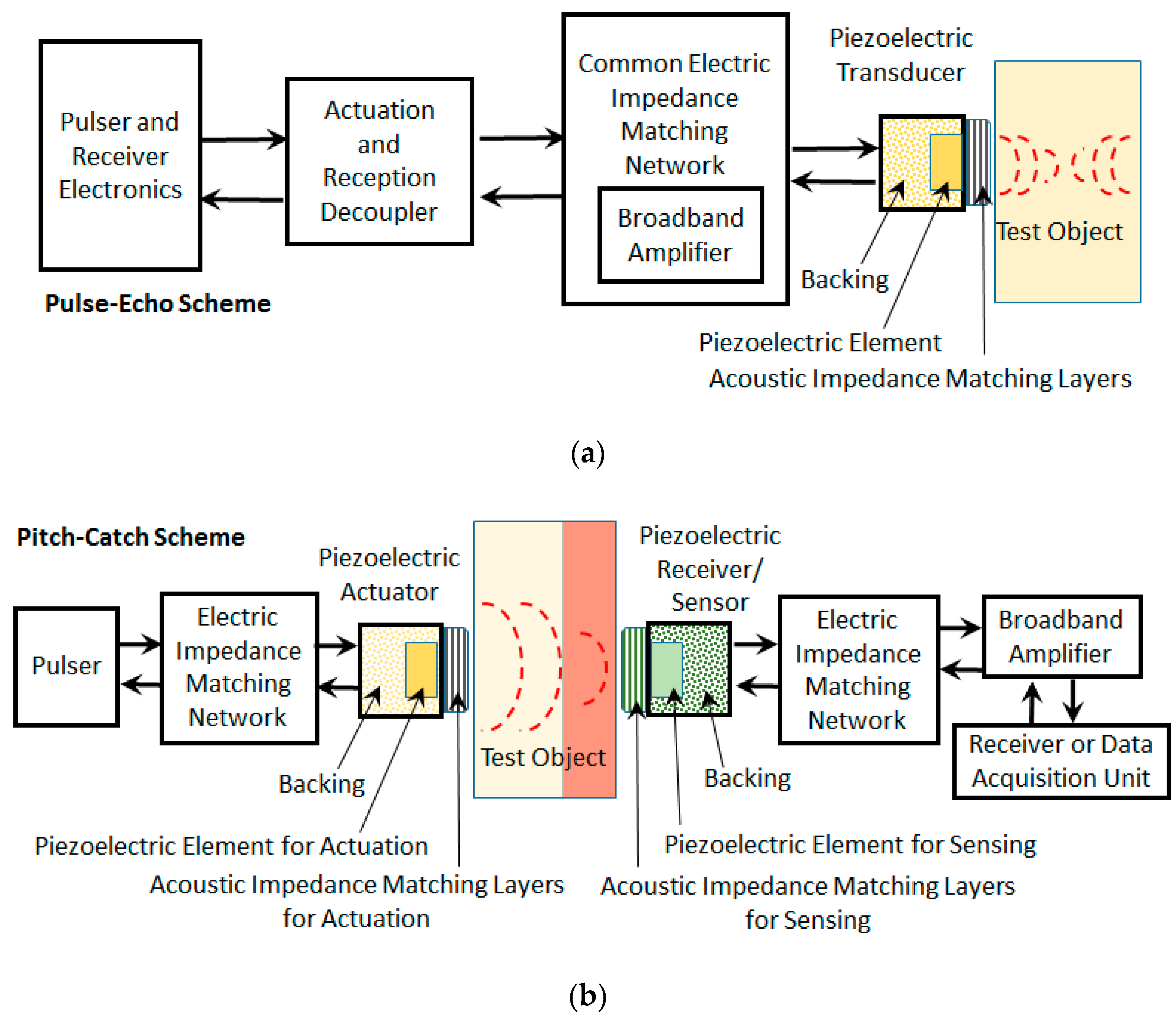
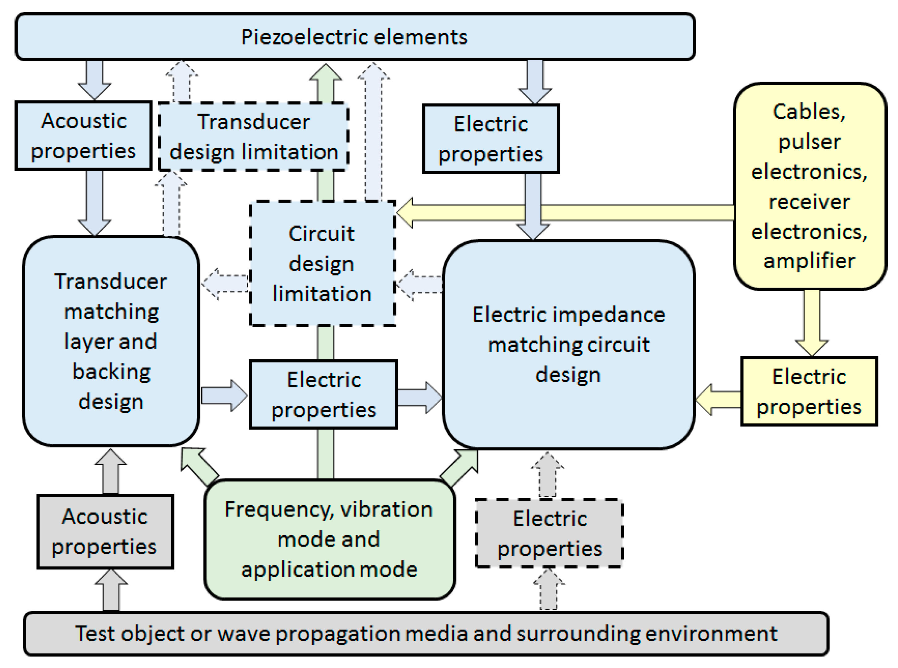
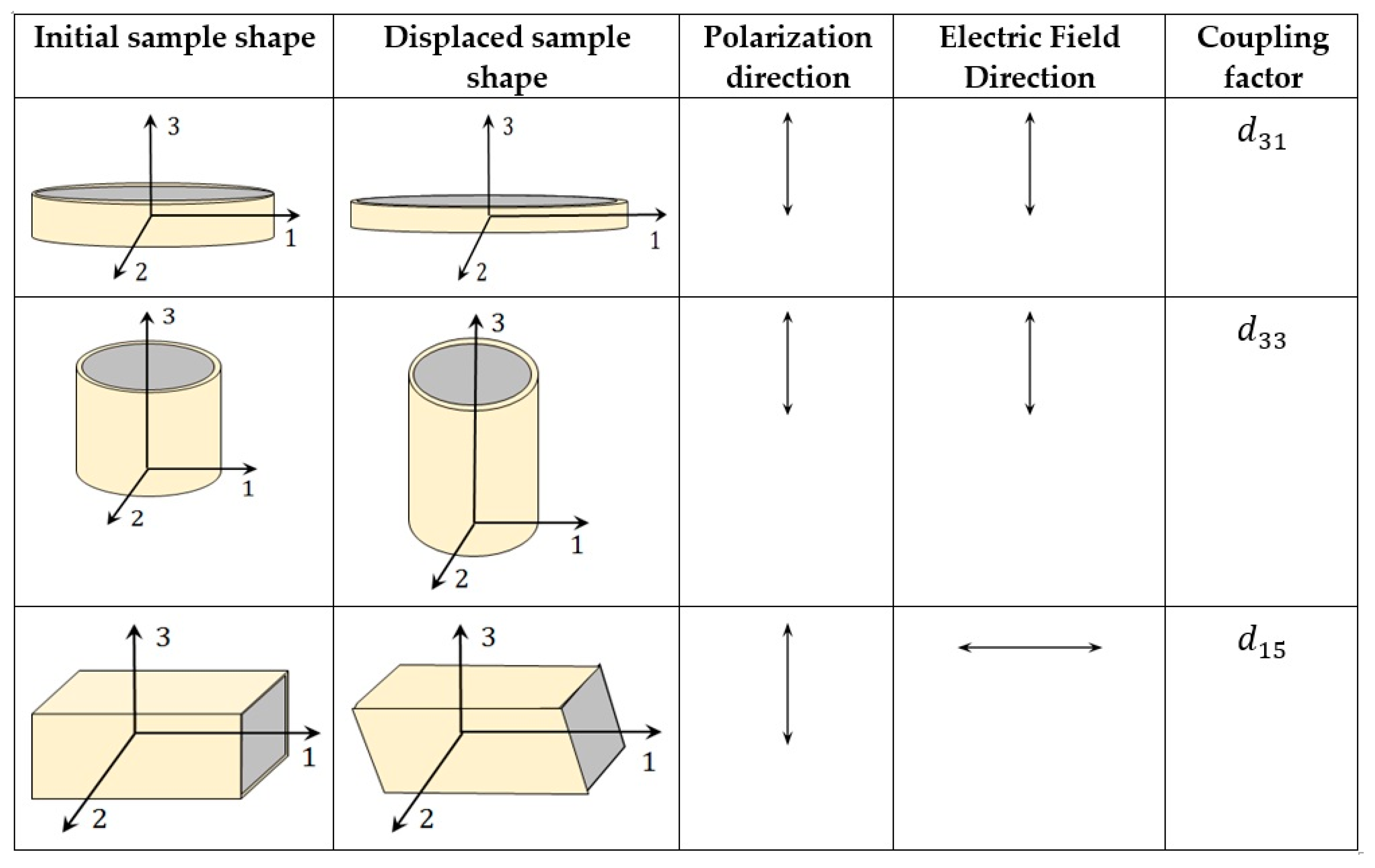
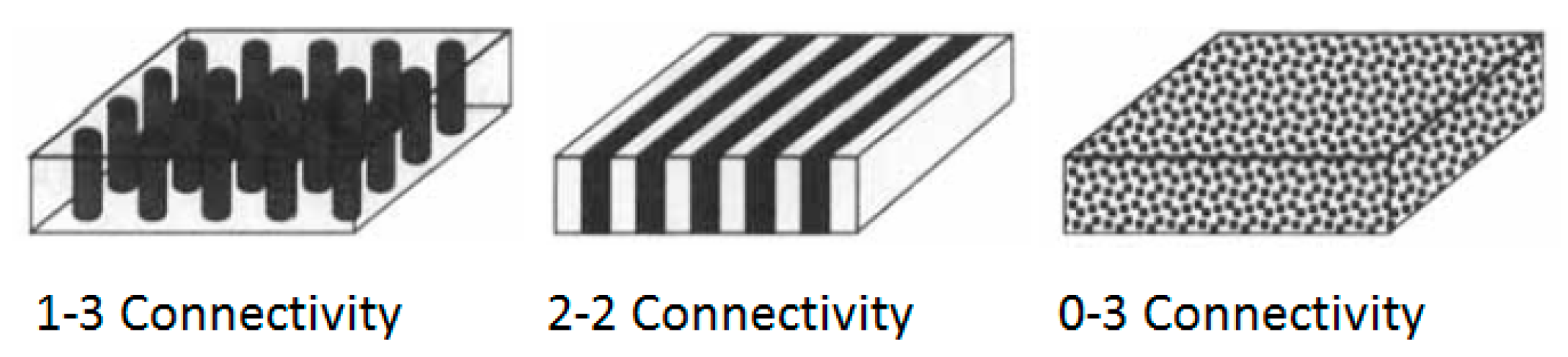
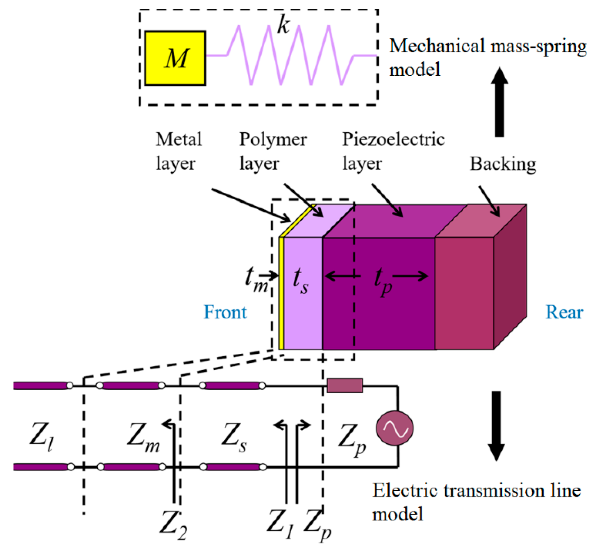
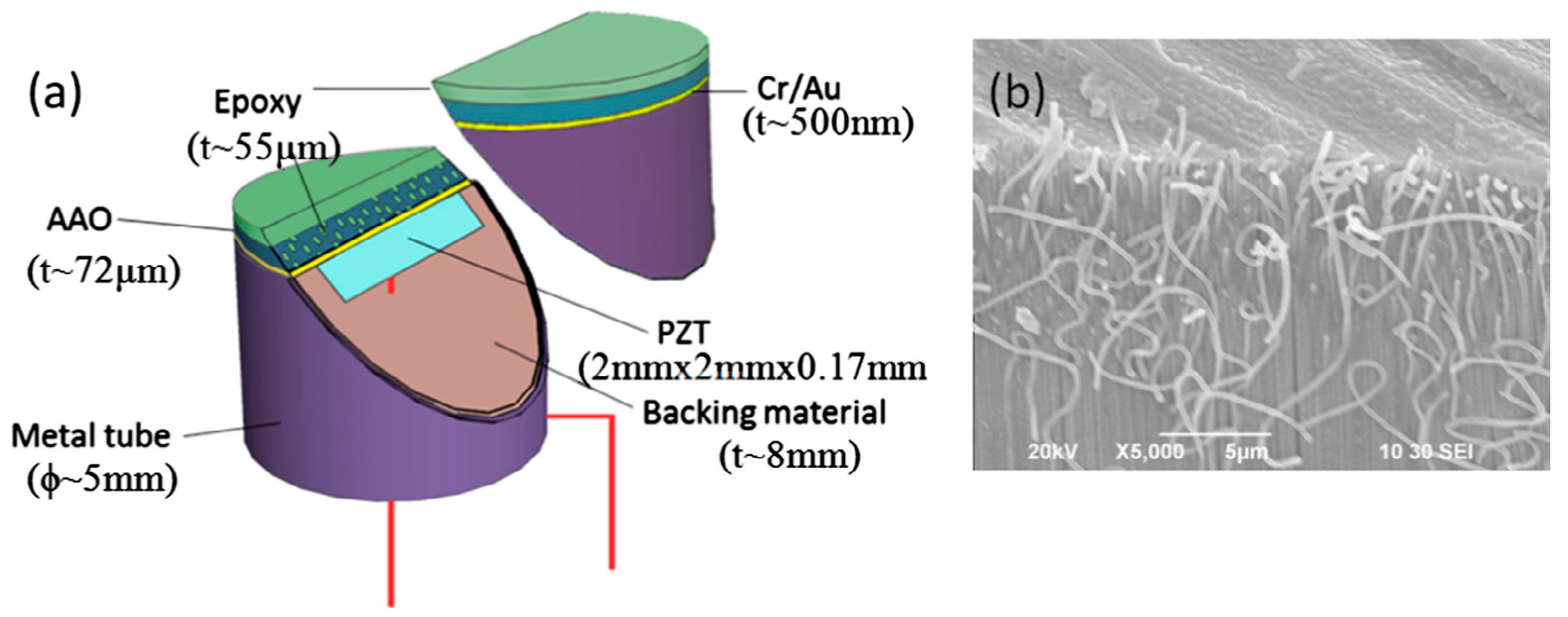
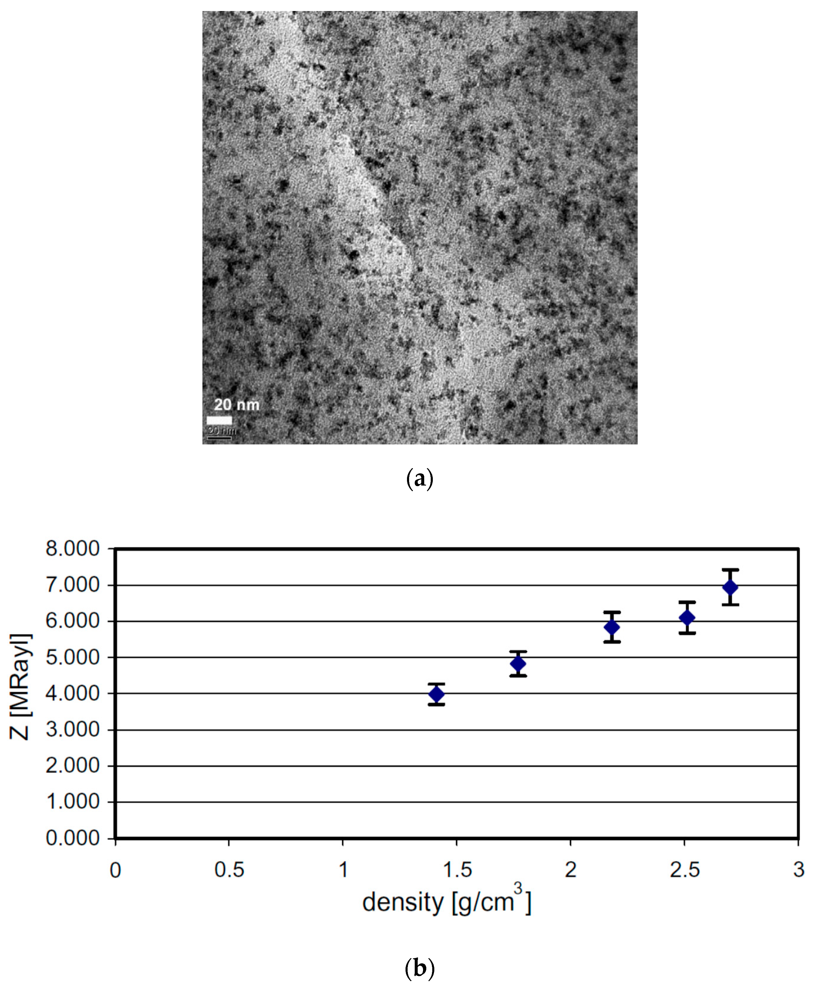
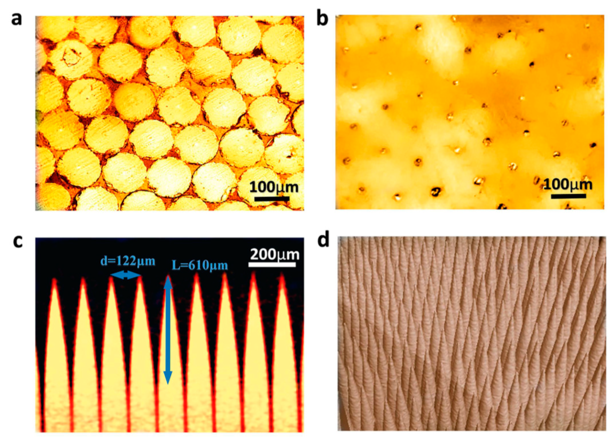
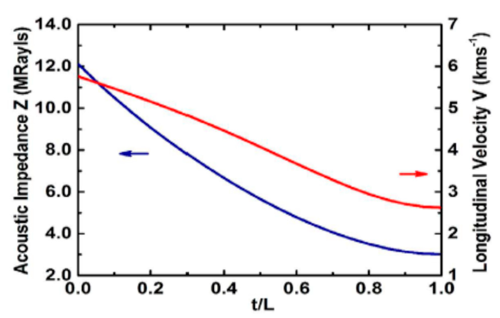
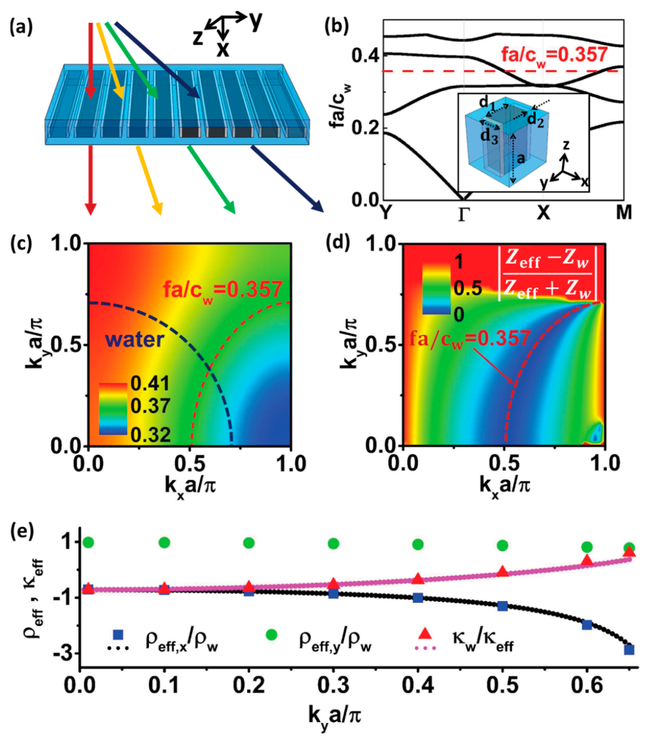
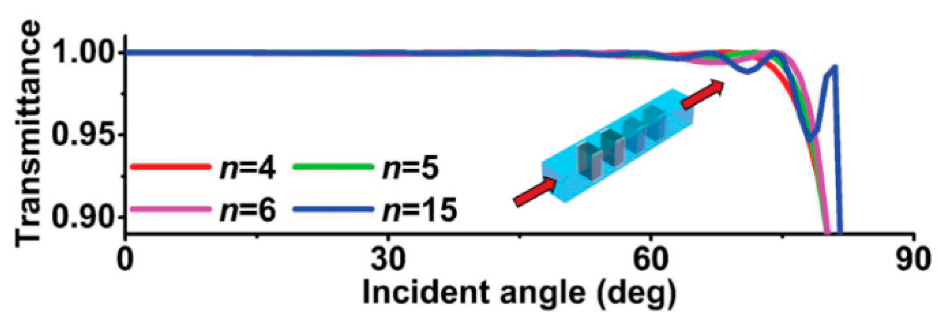
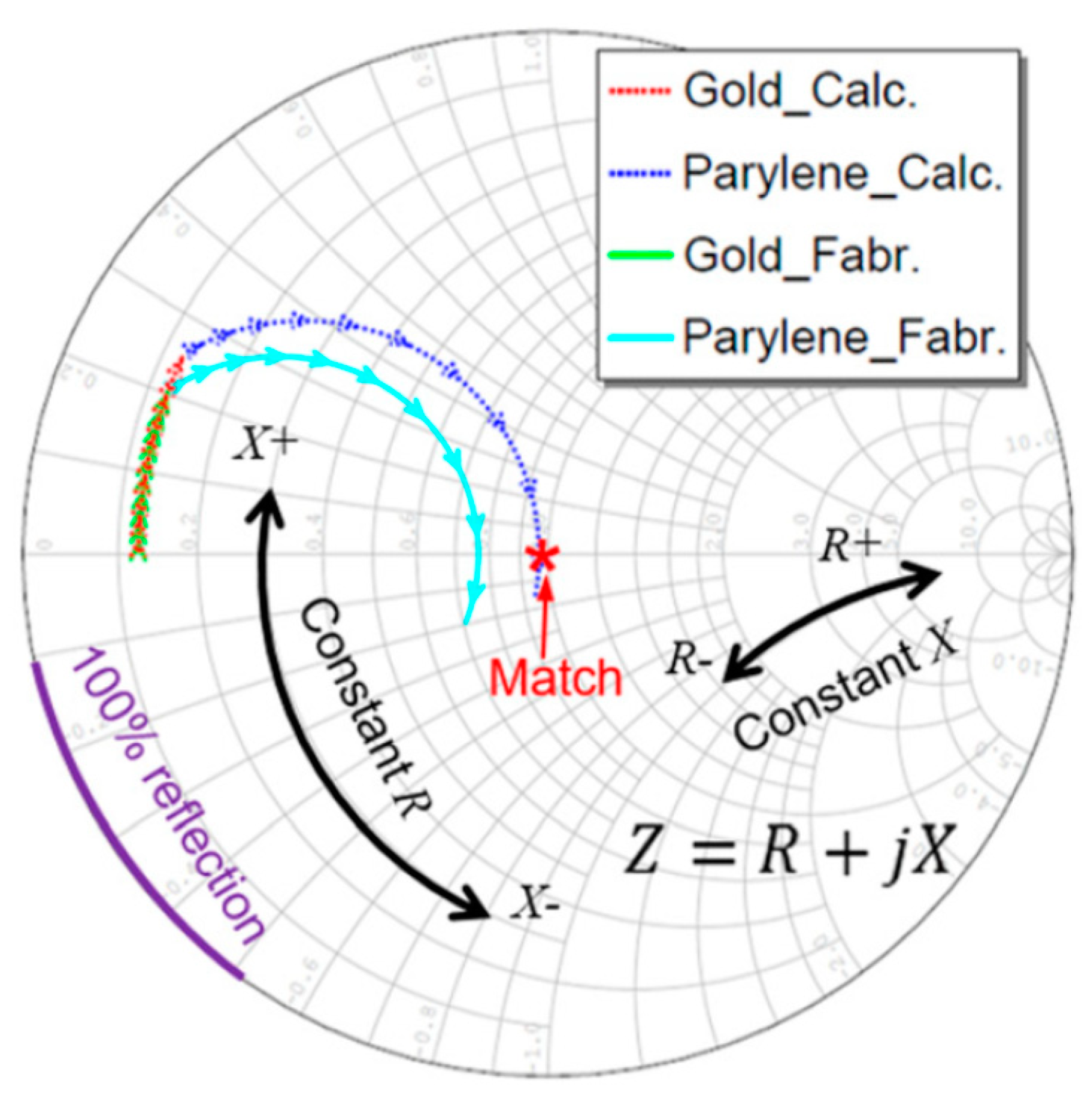
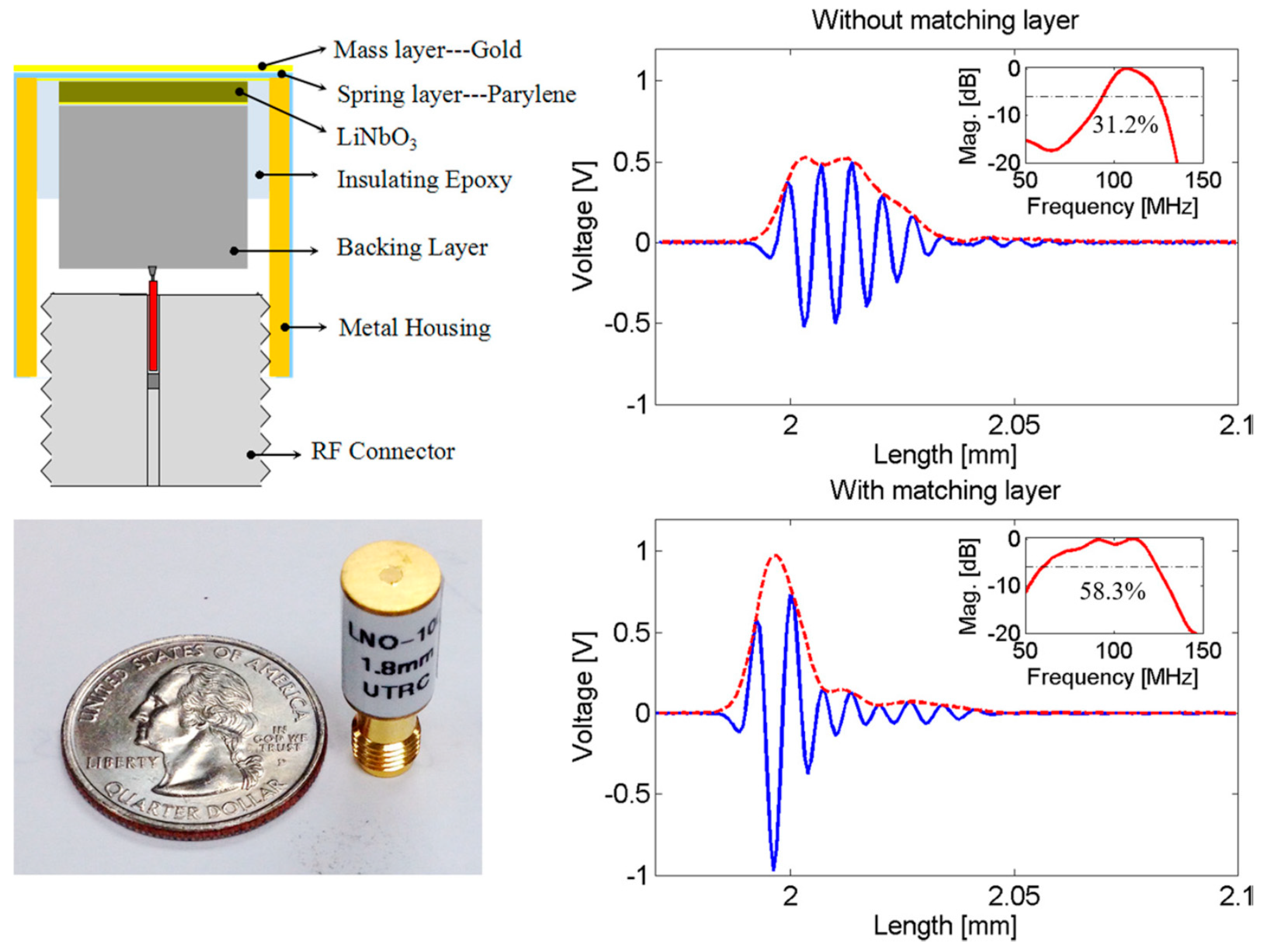
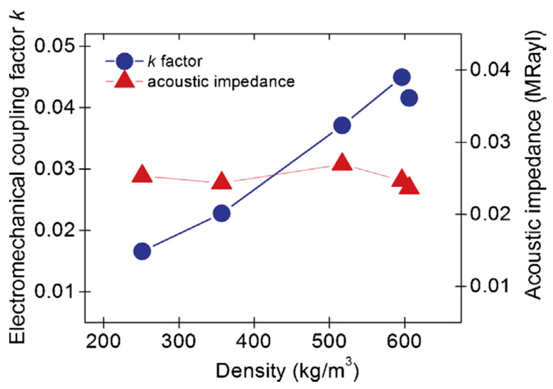
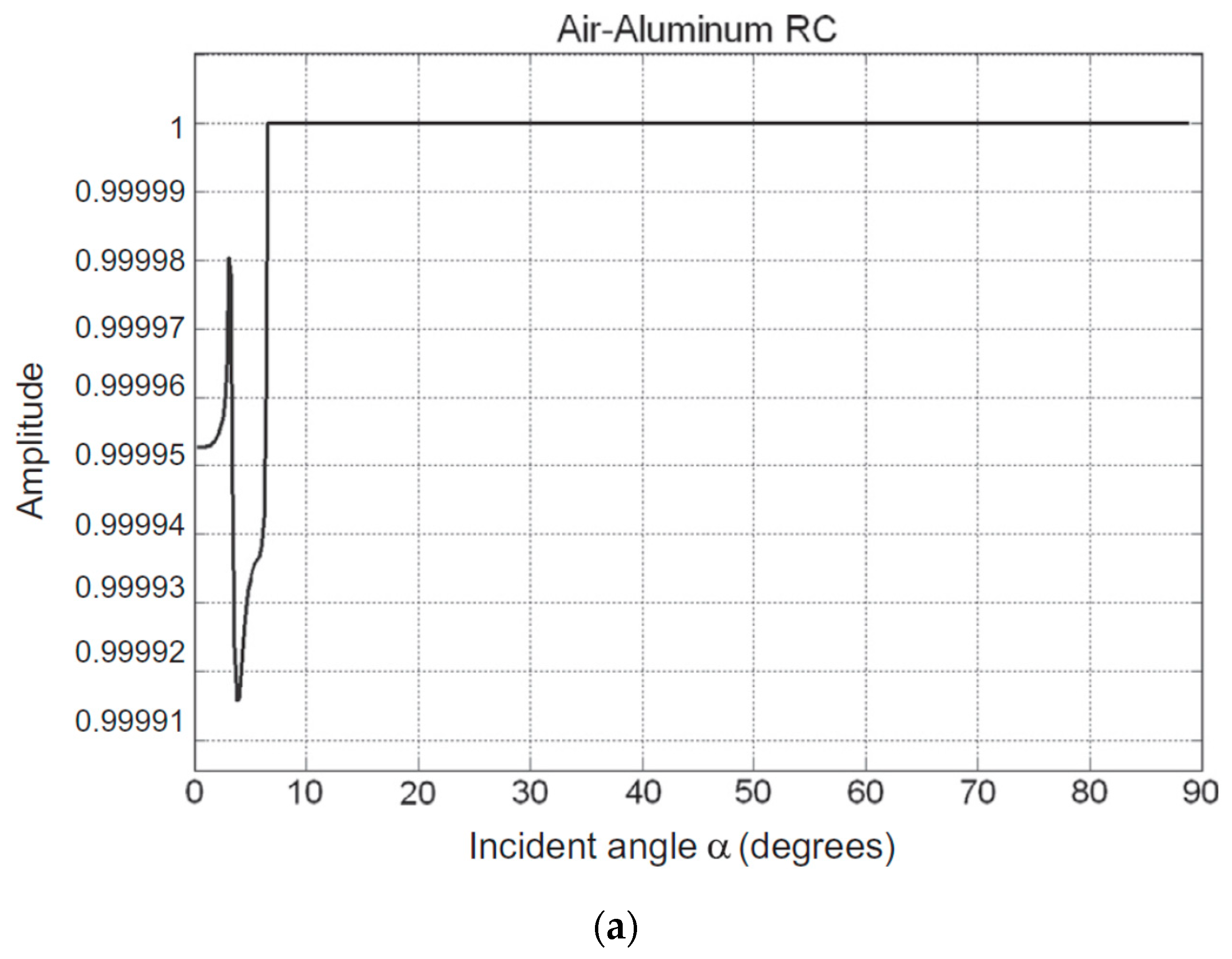
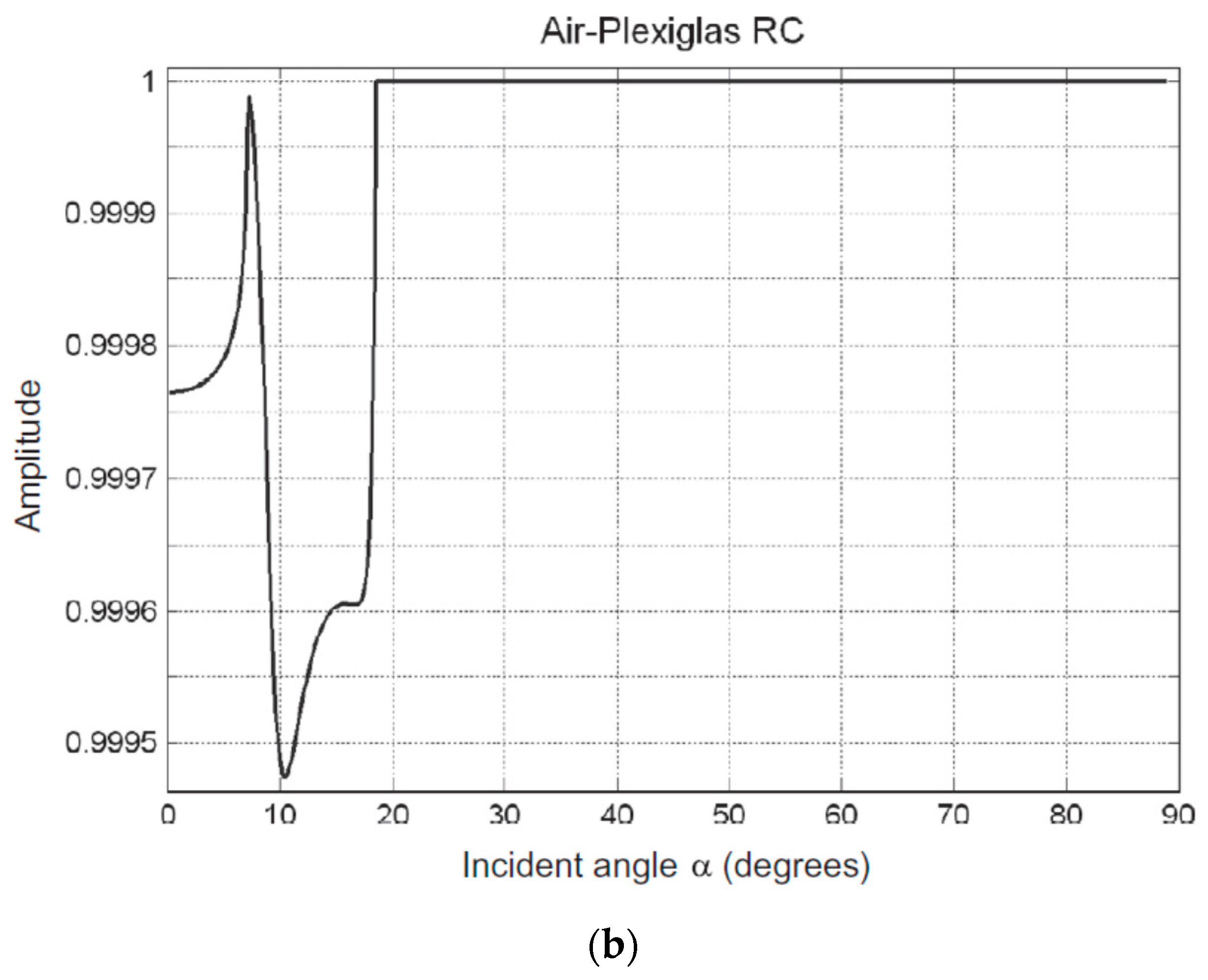
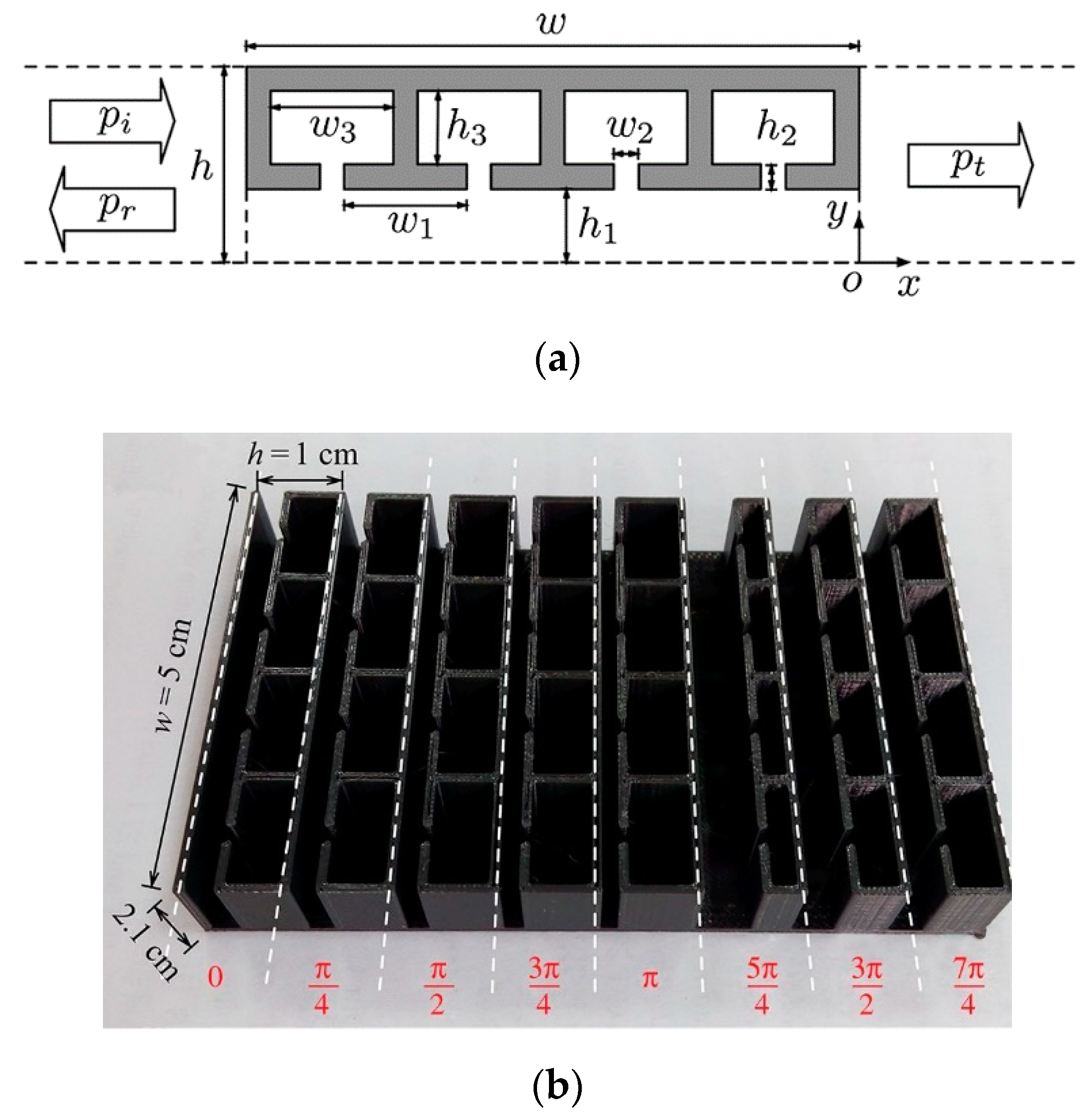
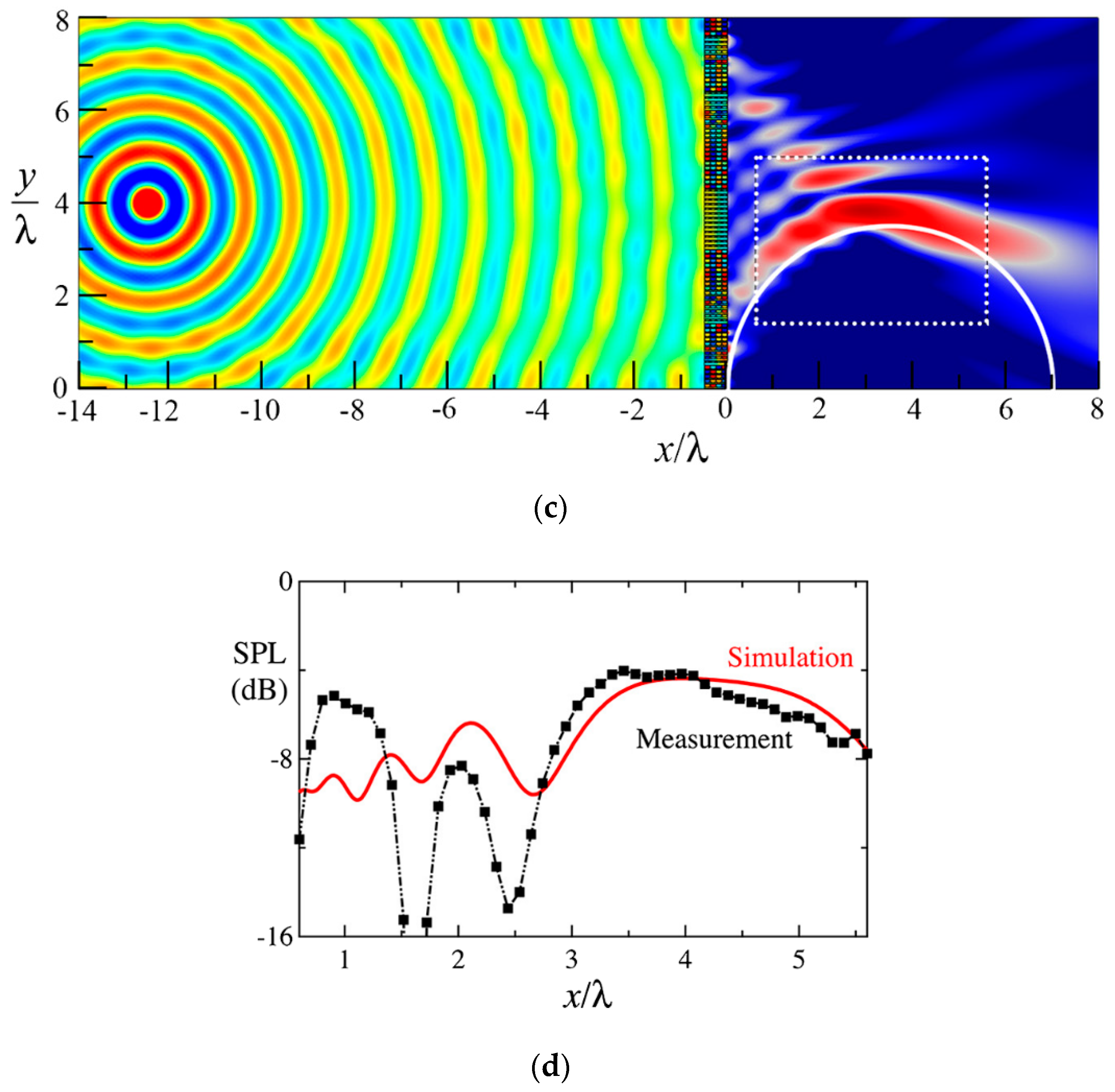
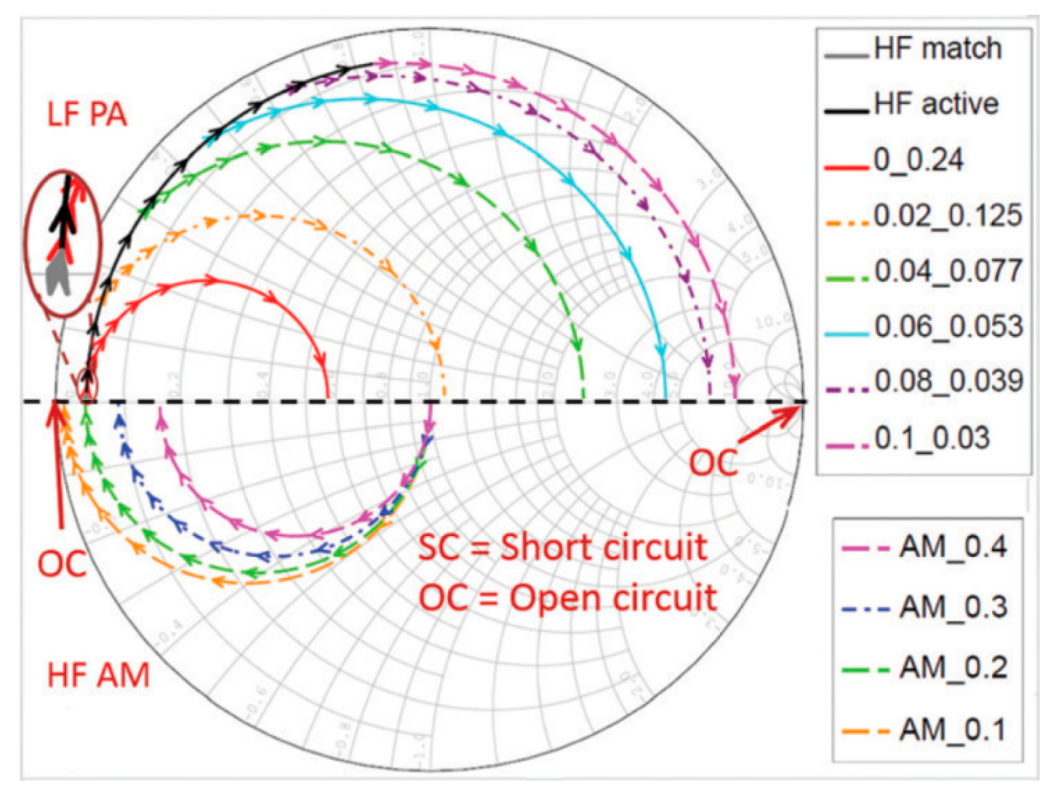
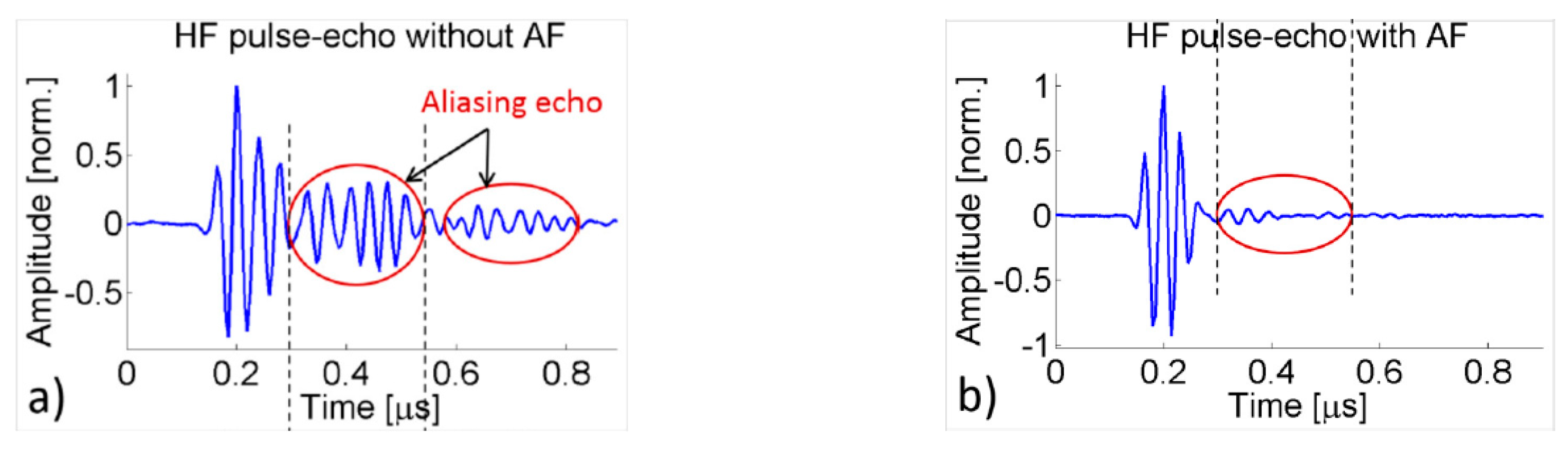
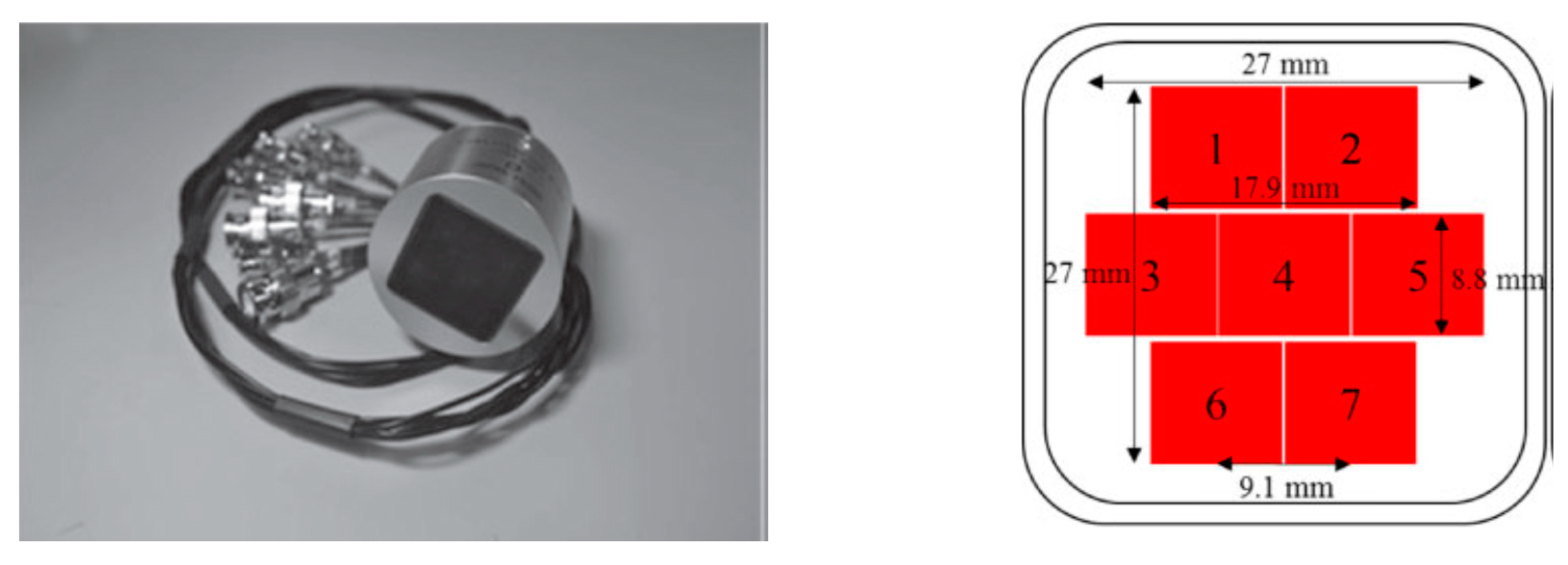
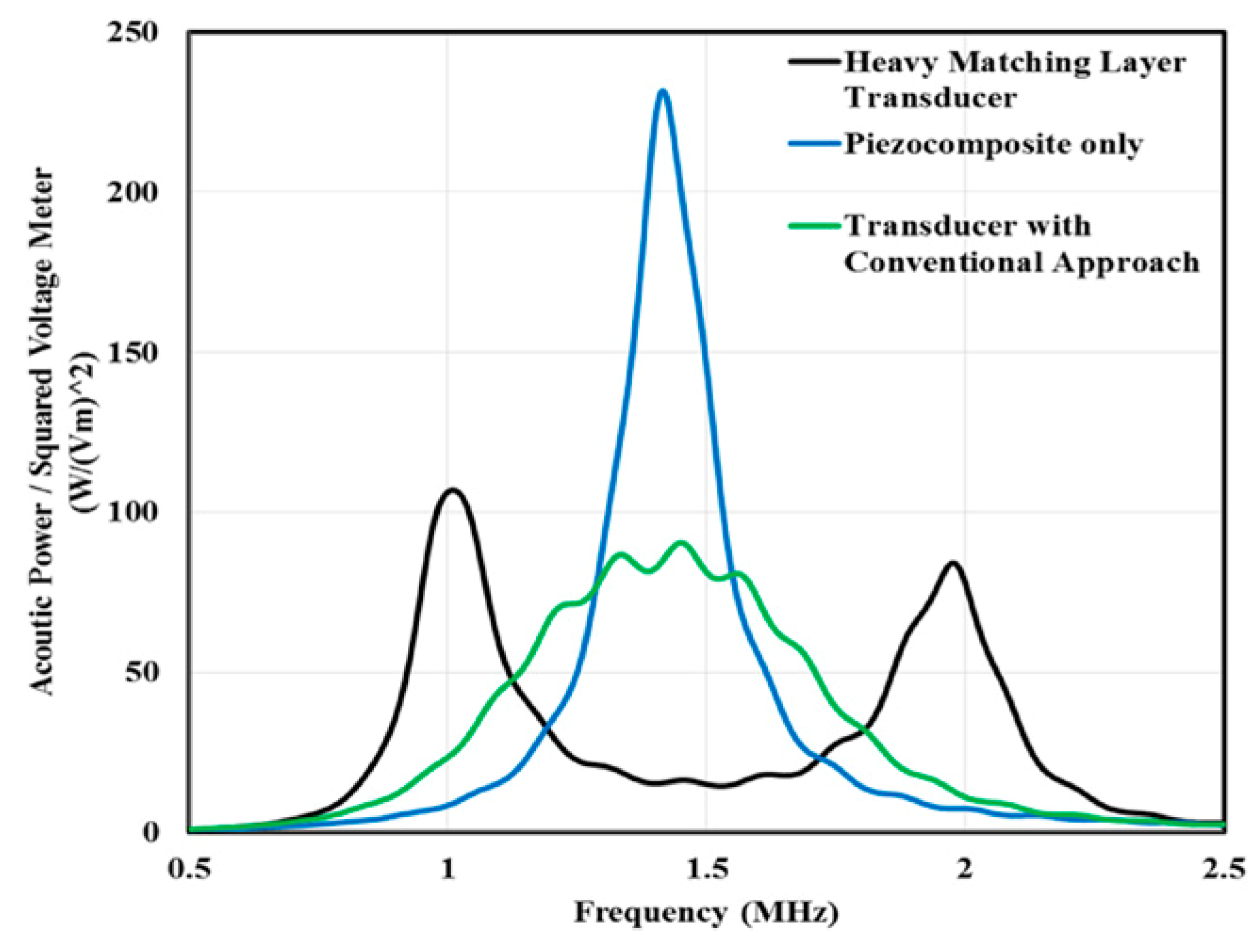
Piezoceramic Lead Zirconate Titanate (Synthetic) [67,75,77,85,101,102]Lead-Free Piezoceramics (Synthetic)
PropertiesPZT4PZT5APZT5HPZT6BPZT7APZT8BaTiO3 [85]KNaNb2O6 [85]LiNbO3 [85,103]PMN–PT (33% PT) [67]
Curie Point (°C)3253652003503503001154201150130
d 33 (pC/N)2853745937115322519012765500
d 31 (pC/N)−122−171−265−27−60−97−78−51-
d 15 (pC/N)495585 13036033026030669
ϵ 33 T 13001700 4604251000170049525
k 33 0.700.710.750.370.670.640.500.600.230.94
k 31 −0.33−0.340.36−0.15−0.30−0.300.21−0.27-
k 15 0.710.69 0.380.680.550.48−0.460.60
g 33 (Vm-N)0.0250.01660.0125
S 33 E (10−12 m2/N)15.518.8 9.3513.913.5---
S 11 E (10−12 m2/N)12.316.4 9.010.711.5---
ϵ 33 T / ϵ 0 1470 --39680–800
ϵ 33 S S / ϵ 0 6358301470385235580---680–800
Mechanical Q 7565 32
ρ (kg/m3)770077007500 5400 46408060
c (m/s)4600 4580 4000 76404610
Z A C O (MRayl)36.1530.0034.3530.0032.00 30 3437.15
T Parameters measured in stress free conditions, E parameters measured in short circuit conditions, Z A C O —acoustic impedance, S i j compliance constants, ρ —density, c —velocity of sound in media, 1 Rayl = 1 N-s/m3 = 1 kg m−2 s−1 [101].
Table 2. Properties of bulk piezopolymers.
PropertiesPVDF [74,113,117,118,119,121]P(VDF-TrFE)
[120,121]
Parylene-C [121] Amorphous   polyimide   PI - ( β -CN) APB/OPDA [121]
Curie Point (°C)160115--
Max temp (°C)90100-220
d 33 (pC/N)−13.6−33.52.05.3–16.5
d 31 (pC/N)5.310.7--
d 32 (pC/N)1.510.1--
d 15 (pC/N)−27−36.3--
g 33 (Vm-N)−0.32−0.38--
k 33 (percent)4.46.20.020.048–0.15
k 31 (percent)3---
k [100]0.15–0.20.3--
Y (GPa)2.5–3.21.1–32.82–3
S 11 D (GN/m2)3.703.01--
S 22 D (GN/m2)3.202.99--
C 33 D (GN/m2)1.513.33--
S 66 D (GN/m2)0.70.69--
ϵ r 12123.154
ϵ 11 T / ϵ 0 6.97.40--
ϵ 22 T / ϵ 0 8.67.95--
ϵ 33 T / ϵ 0 7.67.90--
Tan δ e 0.0180.018-0.01
Tan δ m 0.050.050.060.06
Q [100]1025--
ρ (kg/m3)176018801100–12901420
c (m/s)226024002350-
Z A C O (MRayl)204.512.58-
Y is the Young’s modulus, PVDF is polyvinylidene fluoride, Tan δ e is the dielectric loss, Tan δ m is the mechanical loss, Q is the mechanical quality factor, and k is the electromechanical coupling coefficient.
Table 3. Properties of piezocomposites with different types of piezoelectric fillers such as fibers and particles. MFC: macro fiber composite.
PropertiesMFC
[121,148,149]
PMN-0.29PT/Epoxy [121,150]ZNo/SU-8 20% BURPS
[151]
Macrovoid
[85]
Perforated
[152]
Honeycomb
[85]
Perforated
[152]
Weave
[85]
Laminate
[85,153]
Connectivity1-31-30-33-33-00-33-13-22-32-2
FillerPZTPMN-0.29PTZNoPZT(50%)VoidPZTPZTPZT-PZT (15–30%)
MatrixEpoxyEpoxySU-8 20%EpoxyPZTSilicone rubberPolymerEpoxy-Epoxy
Max use temp (°C)130130180-------
Elastic Constants (GPa) E 1   = 30.34; E 3 = 15.86; G 13 = 5.52;
υ 13 = 0.31
---------
d h (pC/N)714--12015028.31003298050
g h (pC/N)---273032301286516.6
d 33 (pC/N)37412005–8160---290-410 to 440
d 31 (pC/N)170-5------−188 to −200
k 33 (percent)0.530.90.07–0.12-------
k 31 (percent)0.34-0.07-------
ϵ T 85020007500560100400290140340
ρ (kg/m3)5440–75005000--------
Table 4. Acoustic properties of typical piezoelectric transducer materials and media [154,155,156,157,158,159,160].
MaterialTypical Function ρ (kg/m3) c (m/s) Z A C O = ρ c   ( MRayl ) Attenuation or Loss
LiNbO3 CrystalActive element7360468834.5-
QuartzActive element2650574015.2-
PZT5A [100,161]Active element7750435033.70.02 (dB/cm.MHz)
PZT4Active element--36.15-
PMN–PTActive element8100395032.0-
ParyleneMatching layer235011002.58-
GoldMatching layer32401970063.8-
AluminiumMatching layer2700632017-
SteelMatching layer7700590045-
GlassMatching layer3000500015-
PerspexMatching layer118027303.2-
PolystreneMatching layer106023502.5-
AAO–epoxyMatching layer274534609.5-
HDPEMatching layer95123392.2212.41 (Np/m)
Syntactic foamMatching layer70424861.7541.3 (Np/m)
2 µm Al2O3/Epotek 301Matching layer230028006.41.68 (dB/mm at 3.2 MHz)
TeflonMatching layer220013902.97-
PolycarbonateMatching layer122023002.75-
Acrylonitrile-butadiene-styreneMatching layer106025102.68-
PolypropyleneMatching layer92027402.4-
PolysulfoneMatching layer124022402.78-
MylarMatching layer138025403.00-
Epotek 301Lens/Epoxy104826402.81.04 (dB/mm at 3.2 MHz)
E-Solder 3022Conductive backing185032005.9211.8 (dB/mm at 3.2 MHz)
Tungsten powder/µ bubbles/Epotek 301Backing layer357018206.5-
5 µm Tungsten powder/micro bubbles/Epotek 301Heavy backing layer8925180016.016 (dB/mm at 3.2 MHz)
Epoxy EPO-TEK 301Insulation265011503.05-
WaterMedia9971450–14981.445–1.5;
1.48 [155]
0.002 (dB/cm.MHz)
Air (Rayl)Media1.2253430.0004201.64 (dB/cm.MHz)
Tissue (Blood)Media--1.660.15 (dB/cm.MHz)
Tissue (Fat)Media--1.380.6 (dB/cm.MHz)
Tissue (Bone)Media--7.752–15 (dB/cm.MHz)
Tissue (Skin)Media--1.999.2 (dB/cm.MHz)
Concrete [162]Media--8.36–11.3-
HDPE is high density poly ethylene, AAO is anodic aluminum oxide and EPO-TEK is a registered trademark of Epoxy Technology, Inc., and is an adhesive.
Table 5. Comparison of acoustic properties of passive composite and nanocomposite matching layer and their performance.
Transducer TypeActive ElementAcoustic LoadMatching Layer Material Matching   Z A C O   ( MRayl ) BandwidthLossRef
Ultrasonic imaging (12 MHz)Lead zirconate titanate piezo ceramicHuman tissueAAO–epoxy 1-3 composite9.1 and 2.4 for 2 layers68% (−6 dB)2-way insertion −22.7 dB[157]
Ultrasonic imaging (40 MHz)LiNbO3Human tissuealumina/polymer2.8 to 5.1 for single layer35% (−6 dB)15 dB/mm[237]
Medical ultrasound (100 MHz)Zinc oxide layerWatercerium oxide/polymer4.0 to 7.0 for single layer(signal enhanced by 100%)0.5 dB/µm[238]
Medical ultrasound (>50 MHz)PZT piezoceramicsHuman tissueSilicon oxide colloidal/polymer4.4 to 5.8 for single layer--[239]
Ultrasonic imaging (1 GHz)SiliconWaterSu8/TiO23.0 to 6.0-0.5 dB/µm[240]
Medical ultrasound (15 MHz)PZT piezoceramicsHuman tissuesilicon-polymer 1-3 composites5.54 to 6.3250% (−6 dB)-[241]
Table 6. Acoustic properties of typical dental media. c l and c t represent the longitudinal and transverse wave velocity [449,452,453].
Material c l   ( m / s ) c t   ( m / s ) ρ (kg/m3) Z A C O = ρ c   ( MRayl )
Enamel62503100300018.8
Dentin3800190020007.6
Cementum3200--6.5
Dental Pulp157080010001.57
Ligament1580--1.7
Gingiva1540--1.63
Amalgam43502260775033.7

