Article

IR-UWB Pulse Generation Using FPGA Scheme for through Obstacle Human Detection

by
Lalida Tantiparimongkol
and
Pattarapong Phasukkit
*
Department of Electronics Engineering, Faculty of Engineering, King Mongkut’s Institute of Technology Ladkrabang, Bangkok 10520, Thailand
*
Author to whom correspondence should be addressed.
Sensors 2020, 20(13), 3750; https://doi.org/10.3390/s20133750
Submission received: 30 May 2020 / Revised: 22 June 2020 / Accepted: 2 July 2020 / Published: 4 July 2020
(This article belongs to the Special Issue IR-UWB Radar Sensors)

Abstract

:
This research proposes a scheme of field programmable gate array (FPGA) to generate an impulse-radio ultra-wideband (IR-UWB) pulse. The FPGA scheme consists of three parts: digital clock manager, four-delay-paths stratagem, and edge combiner. The IR-UWB radar system is designed to detect human subjects from their respiration underneath the rubble in the aftermath of an earthquake and to locate the human subjects based on range estimation. The proposed IR-UWB radar system is experimented with human subjects lying underneath layers of stacked clay bricks in supine and prone position. The results reveal that the IR-UWB radar system achieves a pulse duration of 540 ps with a bandwidth of 2.073 GHz (fractional bandwidth of 1.797). In addition, the IR-UWB technology can detect human subjects underneath the rubble from respiration and identify the location of human subjects by range estimation. The novelty of this research lies in the use of the FPGA scheme to achieve an IR-UWB pulse with a 2.073 GHz (117 MHz–2.19 GHz) bandwidth, thereby rendering the technology suitable for a wide range of applications, in addition to through-obstacle detection.

1. Introduction

Radar technology first emerged during World War II [1] and has evolved ever since. Apart from military operations, modern radar technology is deployed in numerous applications, including range/speed detection, autonomous driving vehicles [2,3,4,5], detection of objects buried underground (e.g., landmines or pipelines) [6,7,8,9,10], detection of airborne objects [11,12,13], and bio-radiolocation.
In bio-radiolocation, the Doppler radar principle is utilized to remotely detect human life using phase shift of the reflected signal from physiological movements, such as respiration, heartbeat, limb motion [14,15]. In [14], Doppler frequency was used to detect human life through an obstacle (i.e., through-wall detection). Additionally, the Doppler radar method is adopted for medical diagnostics, including sleep apnea, sudden infant death syndrome, and respiratory muscle weakness [16,17,18,19,20,21].
In through-wall detection, there are three conventional radar technologies: continuous wave (CW), frequency-modulated continuous-wave (FMCW), and step frequency continuous wave (SFCW) radars. In [22,23,24], CW radar technology was employed to detect human vital signs underneath the rubble. However, CW radar technology fails to estimate the range (location) of the human buried underneath and requires very strong vital signs for reliable detection [25]. As a result, FMCW and SFCW radar technologies were proposed to address the drawbacks [26,27,28]. Nevertheless, CW, FMCW, and SFCW radars suffer from limited penetration capability [29].
Ultra-wideband (UWB) radar is an unmodulated radar technology that transmits signals across a much wider frequency than conventional radar systems (CW, FMCW, and SFCW). The advantages of UWB radar include high-resolution range measurement, high penetrability, multi-target detection, low susceptibility to atmospheric conditions, detection of barely discernible vital signs, and low power transmission [30,31,32]. As a result, UWB radar technology is widely used for through-wall detection. In addition, UWB radar with S-band frequency (2–4 GHz) can penetrate non-metal solid objects and detect human respiration behind the obstacle [33]. Specifically, UWB radar technology holds promising potential for human detection buried underneath the rubble in the wake of an earthquake.
A field programmable gate array (FPGA) is an integrated circuit which is configurable by a system designer ex post. The advantages of FPGA are high-speed and parallel processing, reconfigurability, and design flexibility [34,35,36,37]. In [38,39], FPGA was deployed to process received signals of through-wall radar systems.
In [40,41,42], integrated circuits (IC) based on complementary metal oxide semiconductor (CMOS) technology were proposed for UWB pulse generation, but the CMOS-based IC suffer from restricted UWB bandwidth. In [43], FPGA was used to generate UWB pulse with a center frequency of 110.25 MHz and a bandwidth of 41.5 MHz (fractional bandwidth of 0.376), rendering it unsuitable for through-wall detection. Based on [43], FPGA was used to generate IR-UWB pulse to improve transmitting frequency bandwidth for radar application, and the proposed FPGA scheme could achieve a bandwidth of 1.6 GHz (fractional bandwidth of 1.033) [44]. In [45], the FPGA scheme was further developed to detect live human subjects behind the wall by arm swing motion. The scheme achieved a bandwidth of 3.83 GHz (fractional bandwidth of 2) and could estimate the range of human subjects by using statistical standard deviation (SD). Table 1 compares previous works on IR-UWB technology and this current research.
This research thus proposes an FPGA scheme to generate IR-UWB pulse to detect from respiration live humans underneath the rubble and to estimate the range in order to locate the human subjects buried underneath. The FPGA scheme consists of three parts: digital clock manager, four-delay-paths stratagem, and edge combiner. Discrete fast Fourier transform is utilized to detect the respiration in terms of doppler frequency, and statistical 7th moment is used to locate human subjects in the range estimation. The proposed IR-UWB radar system is experimented with human subjects lying underneath different layers of stacked clay bricks in supine and prone positions.
The organization of this research is as follows: Section 1 is the introduction. Section 2 describes the proposed FPGA scheme and IR-UWB pulse generation. Section 3 details the human vital sign detection and range estimation algorithms. Section 4 deals with the experimental setup and method, and Section 5 discusses the experimental results. The concluding remarks are provided in Section 6.

2. IR-UWB Pulse Generation and FPGA Scheme

This section describes the ultra-wideband (UWB) pulse mathematical model and the proposed field programmable gate array (FPGA) scheme to generate an impulse radio ultra-wideband (IR-UWB) pulse.

2.1. UWB Pulse Mathematical Model

The UWB pulse signal is mathematically characterized by Gaussian distribution function, which is expressed in Equation (1) [46]:
G ( t ) = A 0 e 1 2 ( t a ) 2
where A0 is the transmission signal amplitude and a = τ/√2 where τ is UWB pulse width.
The multi-order differential Gaussian distribution function is expressed in Equation (2), where Hn(t) is Hermite polynomials that describe differential function (Equation (3)) and n is differential order (n = 0, 1, 2, 3, …) [46,47]. Figure 1 illustrates the 0th, 1st, 2nd, and 3rd order UWB pulse signals using Equation (2):
G n ( t ) = d n d t n G ( t ) = ( 1 ) n 1 a n H n ( t ) G ( t )
H n ( t ) = ( 1 ) n 1 a n e 1 2 ( t a ) 2 d n d t n e 1 2 ( t a ) 2
Specifically, this research proposes a field programmable gate array (FPGA) scheme to generate impulse radio ultra-wideband (IR-UWB) pulse whose shape resembles the 0th order differential Gaussian distribution function (n = 0). The IR-UWB pulse signal, given n = 0, is mathematically expressed in Equation (4) [48]:
s ( t ) = A 0 e ( t τ ) 2

2.2. Field Programmable Gate Array Scheme for IR-UWB Pulse Generation

In [43], an FPGA scheme was experimented to generate a UWB pulse. The scheme could achieve a fractional bandwidth of 0.376, with 110.25 MHz center frequency, 41.5 MHz bandwidth. Such a scheme also requires FPGA with tri-state buffers (TBUF). On the other hand, this current research proposes an FPGA scheme for generation of IR-UWB pulse in gigahertz (GHz) frequency band for detection of live human subjects buried underneath the rubble in the aftermath of an earthquake. Unlike in [43], the proposed scheme utilizes generic FPGA to generate IR-UWB pulse (i.e., Virtex-6 FPGA ML605).
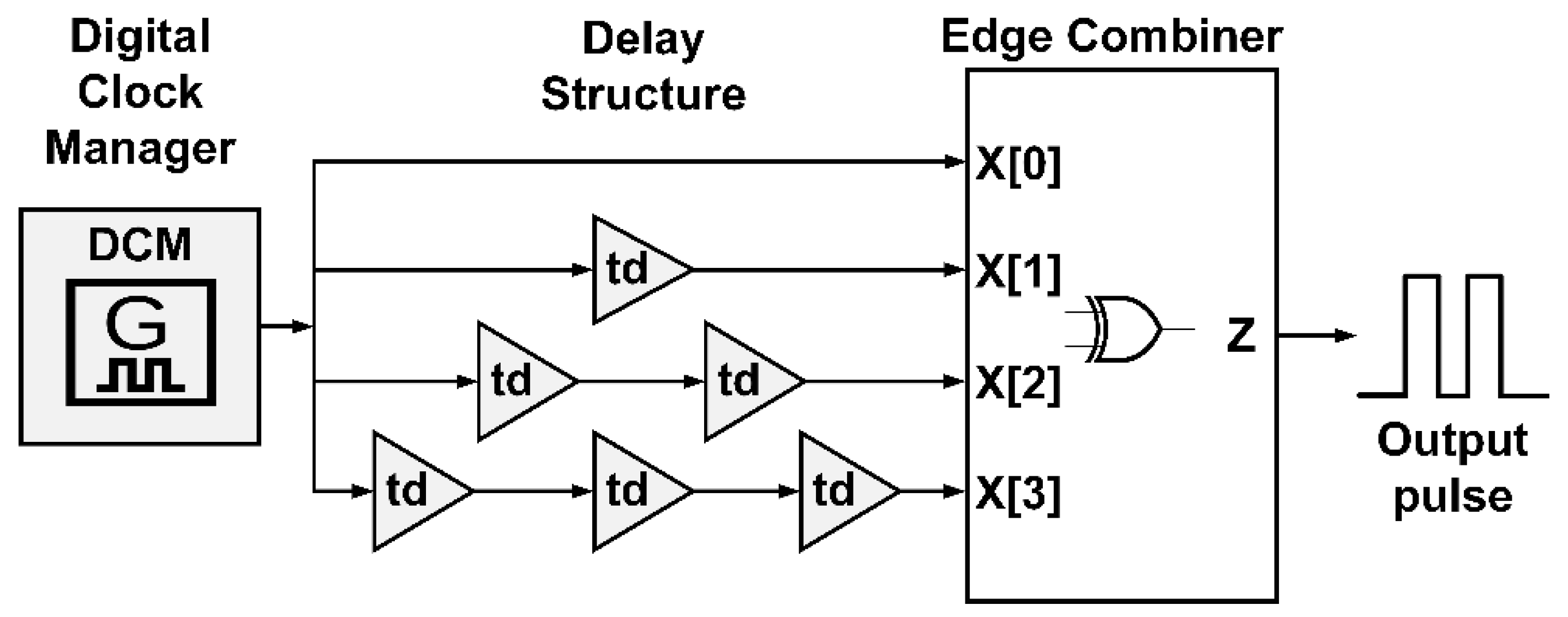
The proposed IR-UWB FPGA scheme consists of three parts: digital clock manager, delay path stratagem, and edge combiner. Figure 2 illustrates the proposed FPGA scheme for IR-UWB pulse generation, where td is delay time of individual buffer logic gates in FPGA architecture.

2.2.1. Digital Clock Manager

In the proposed scheme, the digital clock manager (DCM) in the FPGA intellectual property (IP) core is utilized to manipulate a low-voltage differential signaling (LVDS) oscillator. The LVDS oscillator is an on-board soldered clock source, resulting in highly reliable clock signal.
More specifically, the DCM manipulates the initial clock frequency of the LVDS oscillator to realize predetermined pulse repetition frequency (PRF). In this scheme, the PRF is twice the LVDS initial clock frequency. The initial clock frequency of the LVDS oscillator of Virtex-6 FPGA ML605 is 5 MHz–200 MHz, giving rise to a wider range of PRF compared to [43]. Figure 3 shows the relationship between PRF and the initial clock frequency of LVDS oscillator.

2.2.2. Delay Path Stratagem

In FPGA, time-delay paths are predetermined by configuring the sequence of buffer logic gates. In this research, the delay path stratagem consists of four time-delay paths: X[0], X[1], X[2], and X[3], given 40 nm Virtex-6 FPGA ML605 [49]. The first delay path (X[0]) contains no delay time (td) and the second, third, and fourth delay paths (X[1], X[2], X[3]) have one, two, and three units of delay time, thereby resulting in staggered time-delay paths (Figure 4). To generate an IR-UWB pulse and achieve very broad bandwidth, a minimum delay time (td) is required.
In order to realize the minimum delay time, the delay times of buffer logic gates in FPGA architecture are determined from the look up table (LUT) and the path with the minimum delay time is configurated by using a configuration logic block (CLB) based on the user constraint file. The place and route (P&R) algorithm is implemented to route the configured buffer logic gates. The routing between buffer logic gates is validated by the Xilinx PlanAhead Design and Analysis Tool [50]. Figure 4 depicts the proposed staggered time-delay stratagem with four time-delay paths.

2.2.3. Edge Combiner

In the edge combiner part, exclusive OR (XOR) is applied to four staggered delay paths to achieve four narrow active pulses per cycle, where one active pulse is equal to one unit of delay time (td). LUT algorithm is utilized and functions as concurrent four-input XOR gate. The number of inputs is identical to the four time-delay paths in the delay path stratagem: X[0], X[1], X[2], and X[3]. The output of the edge combiner (z) is fed into onboard coupling capacitor connected with 50Ω SMA connector to generate IR-UWB pulse (o) whose shape resembles the 0th order differential Gaussian distribution function (n = 0). The IR-UWB pulse width is approximately twice the delay time (td).
The advantages of the LUT algorithm are shorter processing time and lower time delay effect, vis-à-vis non-LUT edge combiner. Figure 5 illustrates the edge combiner with LUT algorithm as concurrent four-input XOR gate. Figure 6 shows the four staggered delay paths and four narrow active pulses per cycle, where z is the output of edge combiner.

3. Human Detection and Range Estimation Algorithms

3.1. Vital Sign Model Underneath the Rubble

In theory, electromagnetic (EM) waves which are reflected off an object scatter and/or are captured by a receiver [51,52,53,54,55,56]. The back-scattered signal is mathematically written in Equation (5).
R ( t , τ ) = p σ p s ( t t p ) + o σ o s ( t t o ( τ ) ) + v σ v s ( t t v ( τ ) )
where σp, σo, σv are stationary, non-stationary, and human objects, s(ttv) is time-shifting of the transmitted signal, t and τ are fast-time and slow-time domains.
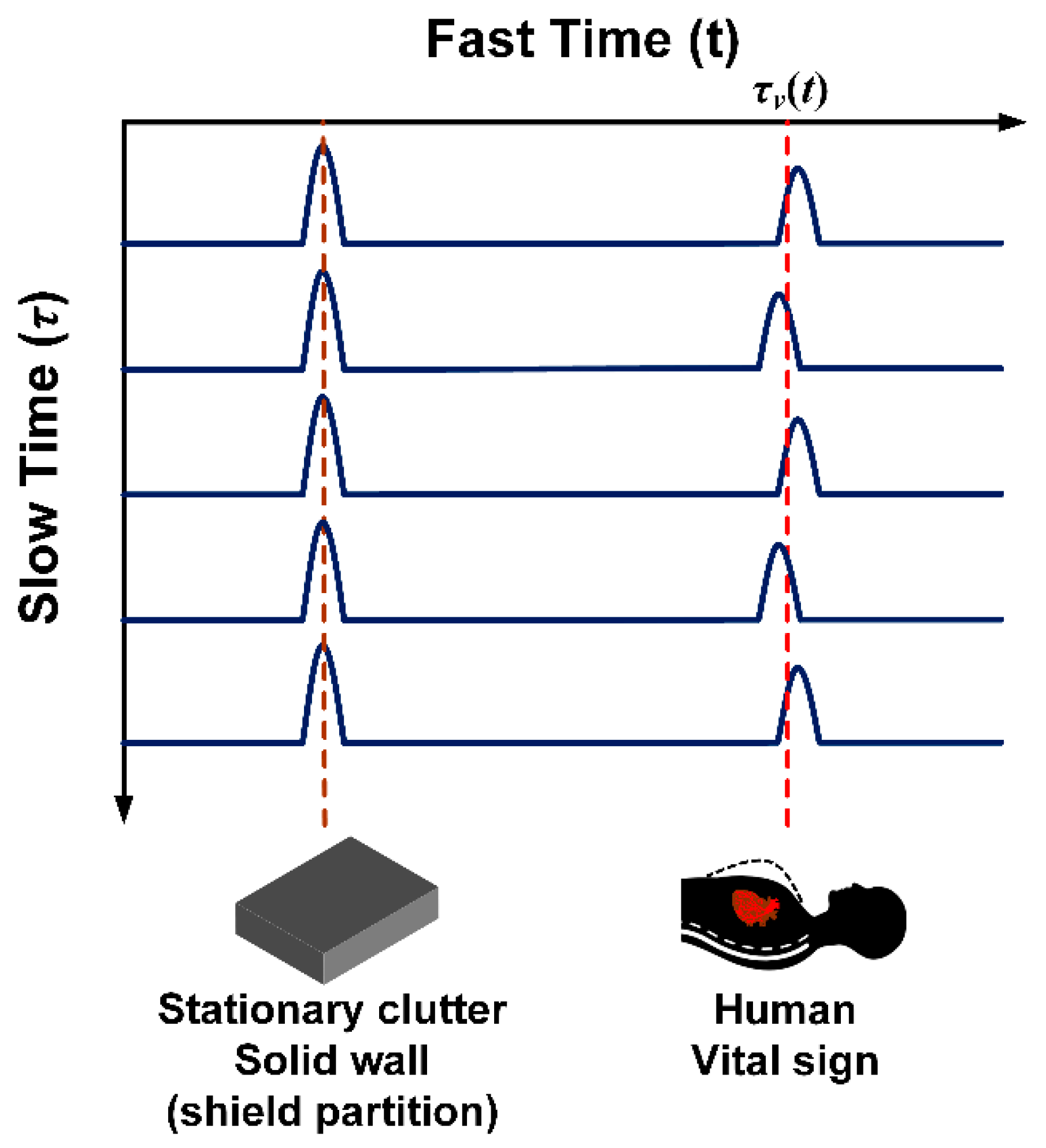
Figure 7 illustrates the reflected signals from the human subject and impenetrable solid object in fast time and slow time. The reflected signals from the human subject are periodic due to the vital signs, i.e., respiration and heartbeat. Meanwhile, the reflected signals from the solid object are static as they are not subject to time shift. As a result, human physiological movements can be determined by time shift of reflected signals.
Since this research focuses on human vital signs (i.e., reflected signals from human), the back-scattered signal in Equation (5) can be simplified as:
R ( t , τ ) = σ v s ( t t v ( τ ) )
where the time delay (tv(τ)) is equal to 2d(τ)/c, where c is the speed of light (3 × 10⁸ m/s). The distance between the transmitting (Tx) antenna and human subject ( d ( τ ) ) is estimated by:
d ( τ ) = d 0 + d h sin ( 2 π f h τ ) + d r sin ( 2 π f r τ )
where d0 is the nominal distance between the Tx antenna and human subject, dh and dr are the movement amplitudes of the heart and respiration, fh and fr are the frequencies corresponding to heartbeat and respiration. From Equation (7), the time delay function can be written in Equation (8):
t v ( τ ) = 2 d ( τ ) / c = t 0 + t h sin ( 2 π f h τ ) + t r sin ( 2 π f r τ )
where t0, tr, and th are the delays related to the human distance, respiratory and heart motions, respectively.
Figure 8 illustrates the distance between antenna and human subject ( d 0 ) as a function of the movement amplitudes of the heart ( d h ) and respiration ( d r ). The proposed through-obstacle IR-UWB radar is of classical monostatic radar, consisting of one Vivaldi transmitting (1-Tx) and one Vivaldi receiving (1-Rx) antenna.
Due to challenges in measuring the back-scattered signal in continuous time (Equation (5)), this research characterizes the back-scattered signal in discrete time [51,52,53,54,55,56,57]. The back-scattered signal in discrete time (R[k,l]) is expressed in Equation (9):
R [ k , l ] = h [ k , l ] + c [ k , l ] + w [ k , l ] + q [ k , l ]
where h[k,l], c[k,l], w[k,l], and q[k,l] are the respiration and heartbeat signals, static signal, white noise, and non-static signal, respectively, where k is discrete domain in fast time of K sampling and l is discrete domain in slow time of L sampling. Preprocessing is subsequently performed to filter out unwanted signals (i.e., static signal, white noise, and non-static signal) to extract the vital signs.

3.2. Preprocessing To Remove Unwanted Signals

The back-scattered signal in discrete time is preprocessed to remove unwanted signals. The unwanted static signal (c[k,l]) is independent of slow time (Figure 7) and can be removed by averaging l by the number of slow time sampling (L). The discrete-time back-scattered signal with the unwanted static signal (c[k,l]) removed is expressed in Equation (10):
Ω n [ k , l ] = R [ k , l ] 1 L l = 1 L R [ k , l ] = h [ k , l ] + w [ k , l ] + q [ k , l ]
In practice, the first and second pulses of back-scattered signal are the antenna coupling and wall/obstacle reflection, respectively. Given the antenna coupling and wall reflection at the minimum detectable range, this research designates the first and second pulses as zero:
Ω [ 1 : K z e r o ,   l ] = 0 ,   where     K z e r o = floor d m i n / Δ d
where dmin is the minimum detectable range and Δ d is the range resolution of radar depending on the speed of light (c) and bandwidth (B) where Δ d = c/2B.
The non-static signal (q[k,l]) and white noise (w[k,l]) are reduced by smooth filter (Equation (12)) and Butterworth bandpass filter (Equation (13)) in fast and slow-time domains:
y [ k , l ] = 1 2 λ + 1 i = λ λ Ω [ k i , l ]
where λ is the number of average data points on either side of Ω [k,l] and 2λ + 1 is the span. The transfer function of Butterworth bandpass filter is expressed as:
| H ( ω ) | 2 = 1 1 + ( ω / ω c ) 2 N f
where ωc is the cutoff frequency and Nf is the filter order and set to 5, giving a good tradeoff between performance and complexity [54]. The discrete-time back-scattered signal with unwanted signals removed is rewritten as:
y [ k , l ] h [ k , l ] + w 0 [ k , l ] + q 0 [ k , l ]            

3.3. Respiratory Rate and Range Estimation

The discrete fast Fourier transform (DFT) algorithm is applied to the discrete-time back-scattered signal in Equation (14) to determine doppler frequency (i.e., respiratory rate). The DFT of the refined discrete-time back-scattered signal is expressed in Equation (15).
Y [ k , f ] = l = 1 L y [ k , l ] e j 2 π f l L
In range estimation, the statistical 7th moment is used to locate human subjects underneath the rubble. From Equation (14), the statistical 7th moment can be expressed in Equation (16), where Equation (17) is the mean of y [ k , l ] in slow time. Figure 9a,b respectively illustrates the DFT doppler frequency (respiration rate) and range estimation using the statistical 7th moment.
μ 7 = 1 L l = 1 L ( y [ k , l ] y ¯ [ k ] ) 7
y ¯ [ k ] = 1 L l = 1 L y [ k , l ]

4. Experimental Setup and Method

This section deals with the generation of IR-UWB pulse using the proposed FPGA scheme and with detection of human subjects underneath the rubble using the FPGA scheme.

4.1. IR-UWB Pulse Generation

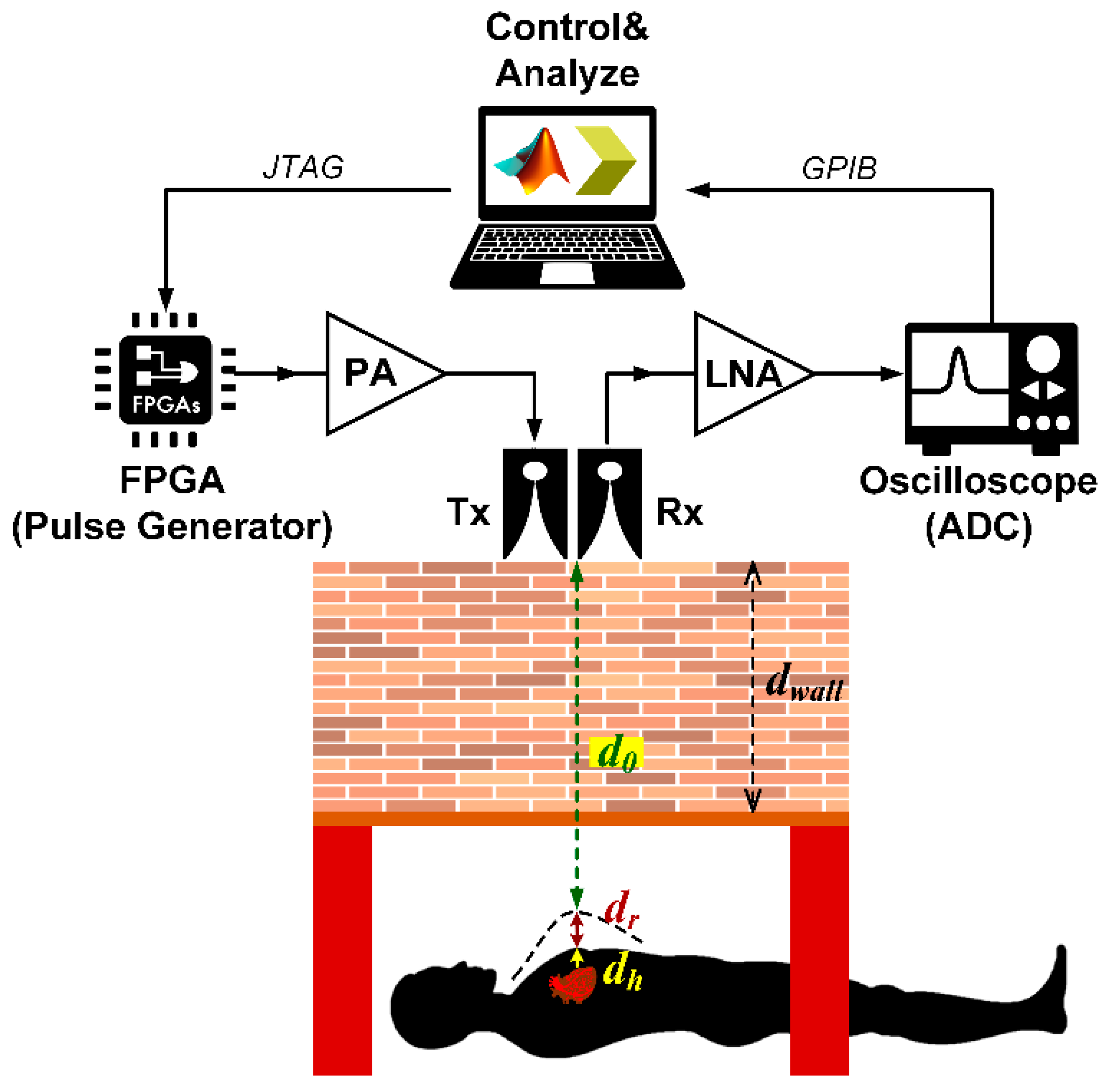
Figure 10 illustrates the schematic of IR-UWB pulse generation using the proposed FPGA scheme. The Verilog HDL programming language is used to create a user constraint file for selectively placing and routing buffer logic gates; and to regulate LVDS clock at 10 MHz. An FPGA bitstream file (.bit) is compiled and programmed into FPGA via Joint Test Action Group (JTAG) connector. The setup is verified by embedded hardware monitoring function ChipScope Pro Analyzer.
The IR-UWB pulse from FPGA is fed into oscilloscope via co-axial transmission line. A computer is used to retrieve digital data via general purpose interface bus (GPIB) for MATLAB analysis to determine the pulse duration and bandwidth. Table 2 tabulates the experimental components and specifications.

4.2. Detection of Human Underneath the Rubble

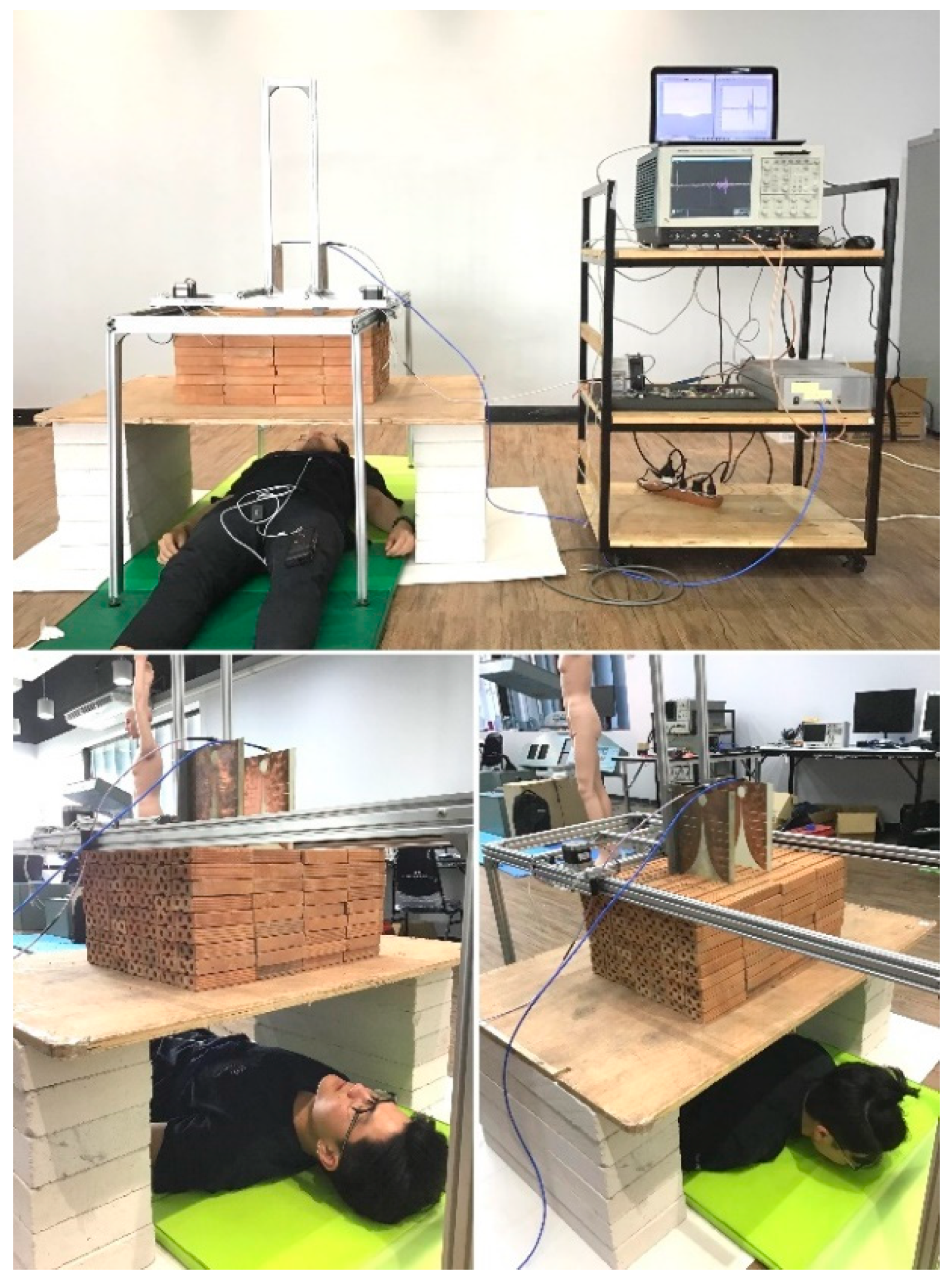
To simulate detection of human subjects buried underneath the rubble, this research used layers of stacked clay bricks as a substitute for collapsed walls. Figure 11 depicts the experimental setup for detection of human subjects underneath layers of stacked clay bricks in supine and prone positions using the FPGA scheme. The human participants were instructed to remain physically stationary over the course of experiment.
In the experimental detection, there were three male and three female healthy participants. The human subjects individually lay underneath layers of stacked clay bricks with Tx and Rx Vivaldi antennas sitting atop. The distance between Tx and Rx antennas is 15 cm, and the radar-antennas set is motionable horizontally and vertically.
The layers of stacked clay bricks on 1.5 cm-thick plywood were varied between 3, 6, and 9 layers (9, 18, and 27 cm in thickness). The distances between the Tx-Rx antennas and participating human subjects underneath the stacked clay bricks were 20.5–47 cm, depending on the number of brick layers (3, 6, and 9 layers) and gender. The vital sign detection experiments were carried out with participants in supine and prone position. The data acquisition duration for each individual participant in either position was 3 min with 256 slow-time pulses and 5000 fast-time datapoints.
In addition, the six participants wore a respiration sensor (BioRadioTM respiratory kit) around their chest to monitor respiration rhythm. The experimental measurement using the proposed IR-UWB FPGA scheme was validated against the readings by the respiration sensor. Figure 12 shows the schematic of IR-UWB pulse generation using FPGA scheme for detection of human subjects underneath layers of stacked clay bricks. The specifications of the experimental components and equipment are presented in Table 2.

5. Experimental Results and Discussion

This section discusses IR-UWB pulse generated by the proposed FPGA scheme and the human detection performance of the IR-UWB radar system in terms of respiratory rate and range estimation.

5.1. IR-UWB Pulse Generation Using FPGA Scheme

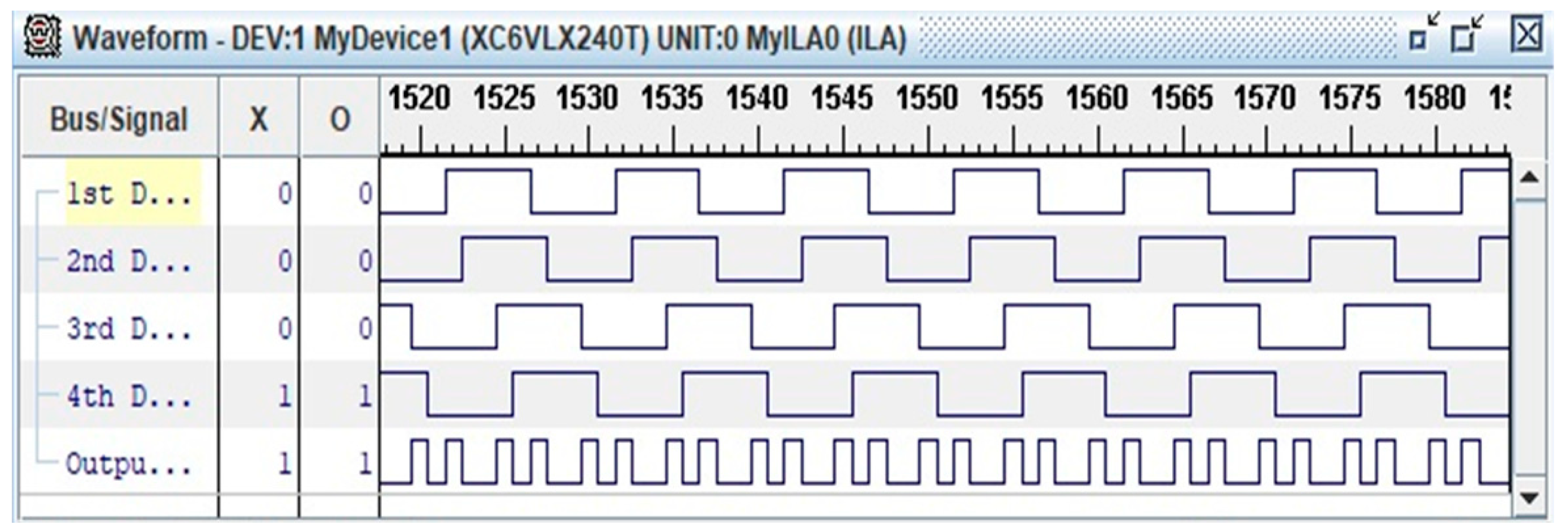
Figure 13 illustrates the waveform of LUT four-input XOR gate by using ChipScope Pro Analyzer function. The waveform is identical to the schematic of four staggered delay paths and four narrow active pulses or delay time (td) per cycle (Figure 6). One unit of delay time (td) is approximately 270 ps.
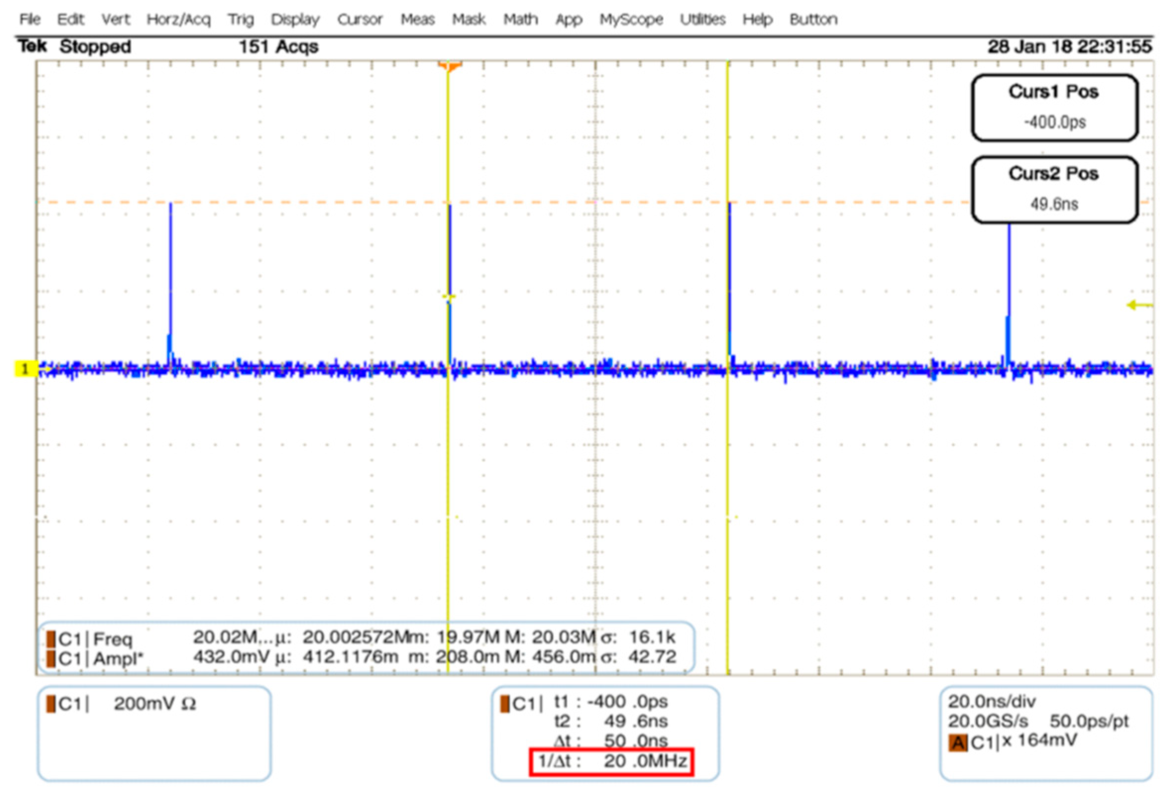
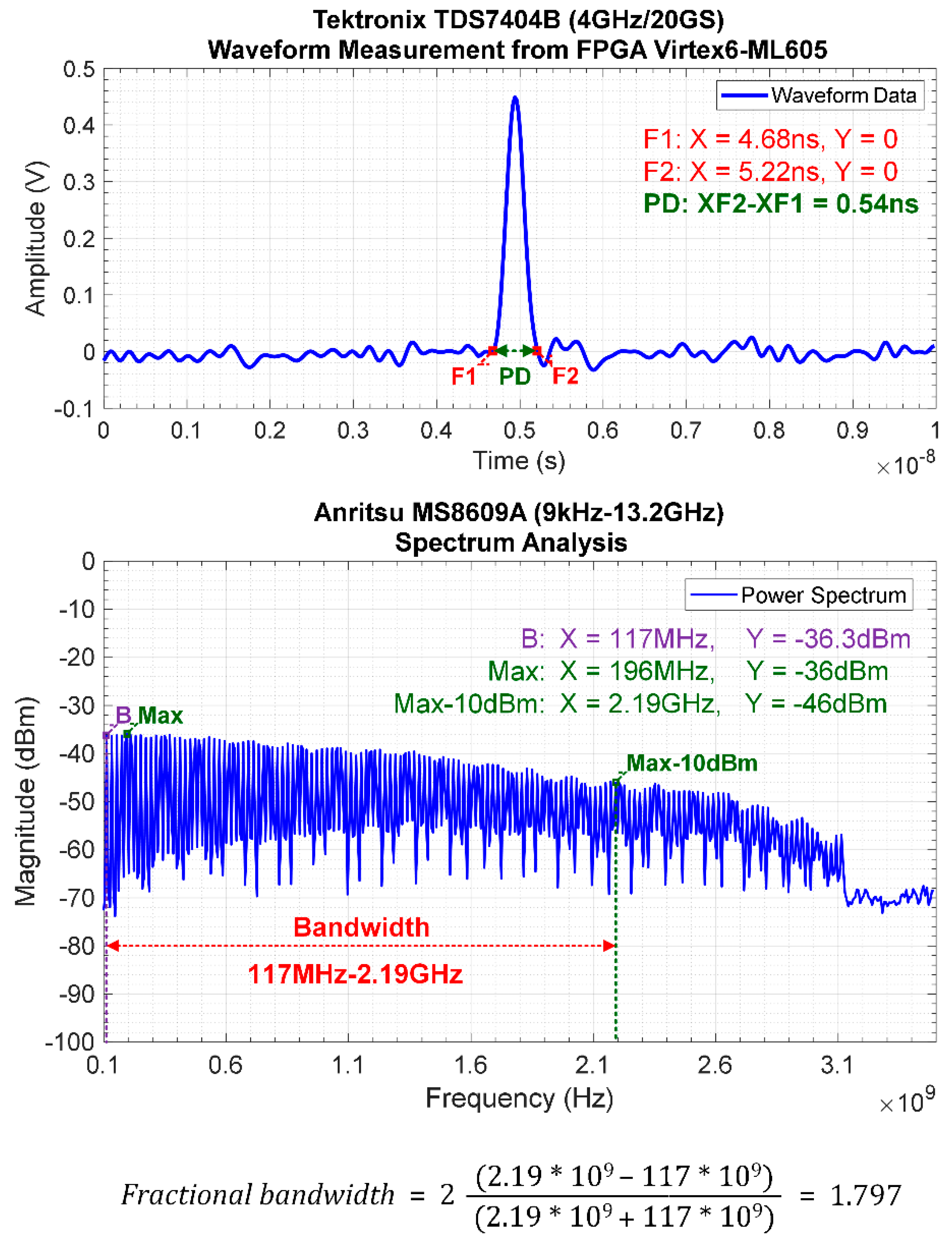
Figure 14 depicts the IR-UWB pulse generated by the FPGA scheme with pulse repetition frequency (PRF) of 20 MHz using oscilloscope. Given the LVDS clock of 10 MHz, the PRF of IR-UWB is 20 MHz, which is twice the LVDS clock frequency. The digital data from the oscilloscope and spectrum analyzer were retrieved via GPIB to characterize the pulse duration and bandwidth using MATLAB, as shown in Figure 15. The pulse duration is 540 ps, which is approximately twice the delay time (td), and the bandwidth is 2.073 GHz (117 MHz–2.19 GHz, fractional bandwidth of 1.797), given the Federal Communications Commission (FCC)’s normalized magnitude ≥ −10 dB. The realized IR-UWB bandwidth falls within the S-band frequency (2–4 GHz).

5.2. Human Detection Performance of IR-UWB Radar System

This sub-section discusses the performance of the proposed IR-UWB radar system to detect human respiration and locate the human subjects underneath the rubble (range estimation). As previously stated, this research used layers of stacked clay bricks to simulate detection of human subjects buried underneath the rubble. Since the detection results of the six participating human subjects are insignificantly different, this part thus presents the findings of one single participant.

5.2.1. Respiratory Rate Estimation

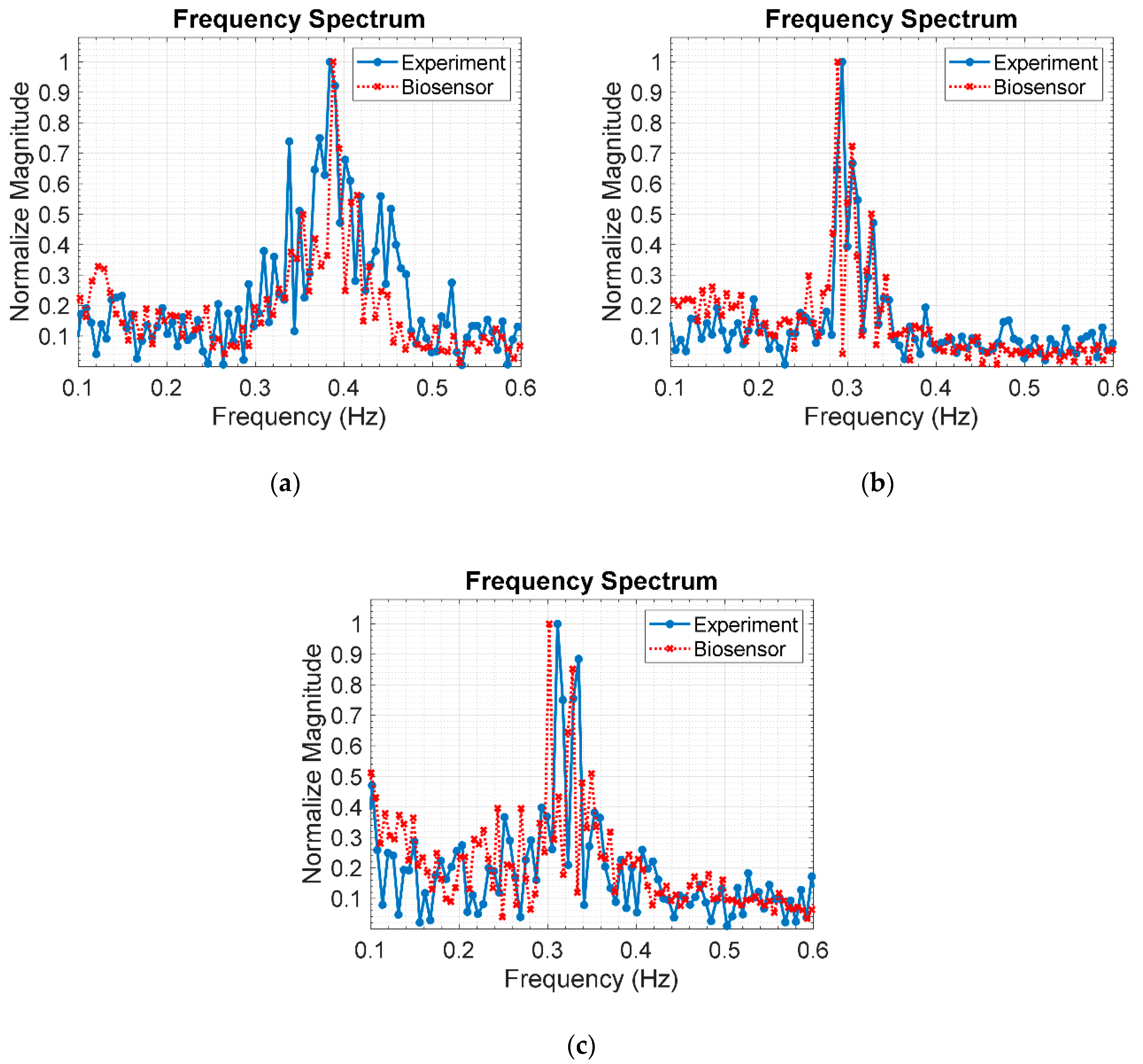
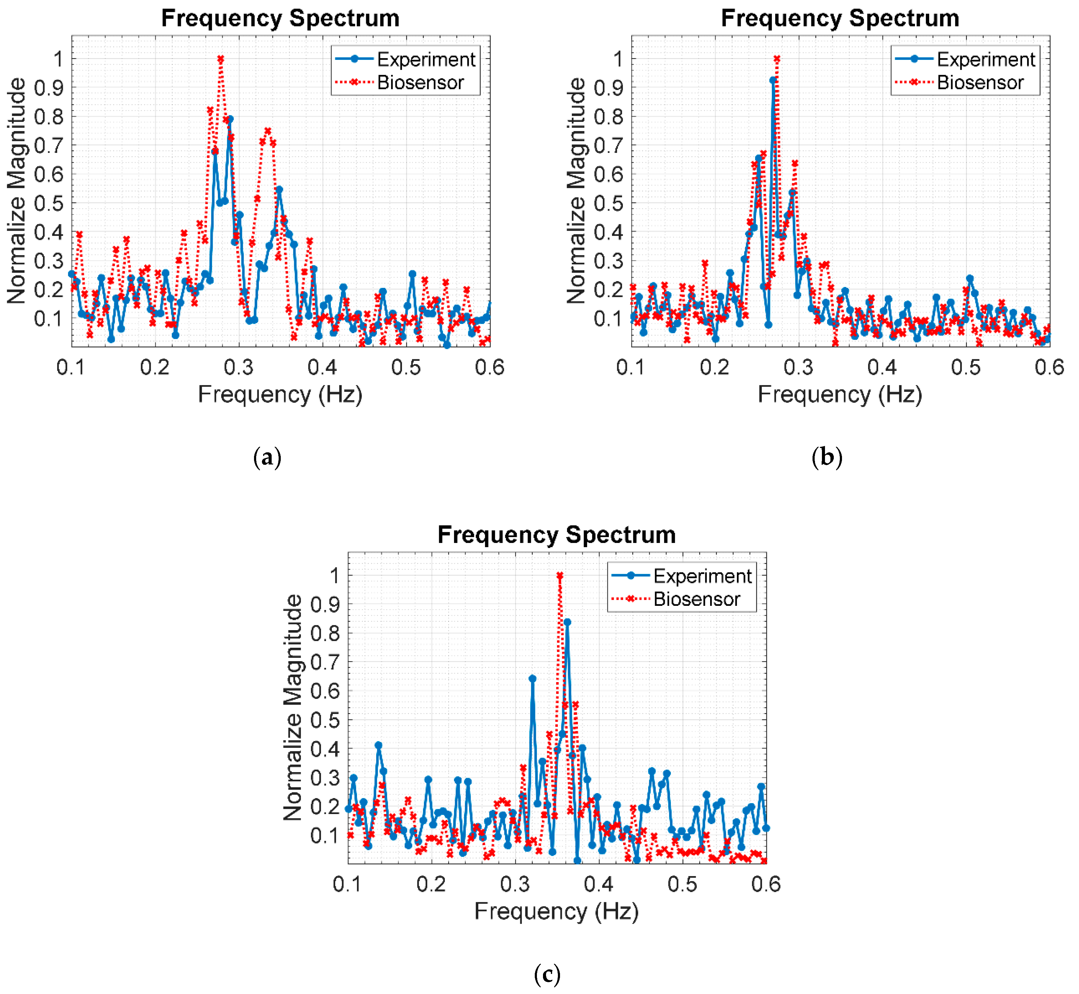
Figure 16a–c respectively illustrates the respiratory frequency of a human subject in supine position under layers of stacked clay bricks: 3 (9 cm), 6 (18 cm), and 9 layers (27 cm), using the IR-UWB radar system and respiration sensor. The experimental respiratory frequency, as indicated by the maximum frequency peak, are 0.3842 Hz (23 breaths/min), 0.2938 Hz (17.6 breaths/min), and 0.3111 Hz (18.7 breaths/min) for 3, 6, and 9 layers of stacked bricks. The corresponding benchmark respiratory frequency, as measured by the respiration sensor, are 0.3878 Hz (23.3 breaths/min), 0.2888 Hz (17.3 breaths/min), and 0.3017 Hz (18.1 breaths/min). The experimental and benchmark respiratory rates are in good agreement, suggesting that the proposed IR-UWB radar system is applicable to localization of human buried underneath the rubble.
Figure 17a–c respectively depicts the respiratory frequency of the human subject in the prone position under different thicknesses of clay bricks: 9 (3 layers), 18 (6 layers), and 27 cm (9 layers), using the IR-UWB radar system and respiration sensor. The experimental respiratory frequencies are 0.2890 Hz (17.3 breaths/min), 0.2694 Hz (16.2 breaths/min), and 0.3621 Hz (21.7 breaths/min) for 3, 6, and 9 layers of stacked bricks. The corresponding benchmark respiratory frequency, as measured by the respiration sensor, are 0.2781 Hz (16.7 breaths/min), 0.2738 Hz (16.4 breaths/min), and 0.3531 Hz (21.2 breaths/min). The experimental and benchmark respiratory rates are in good agreement, indicating that the IR-UWB radar system is applicable to human localization underneath the rubble.

5.2.2. Range Estimation Based on Doppler Frequency

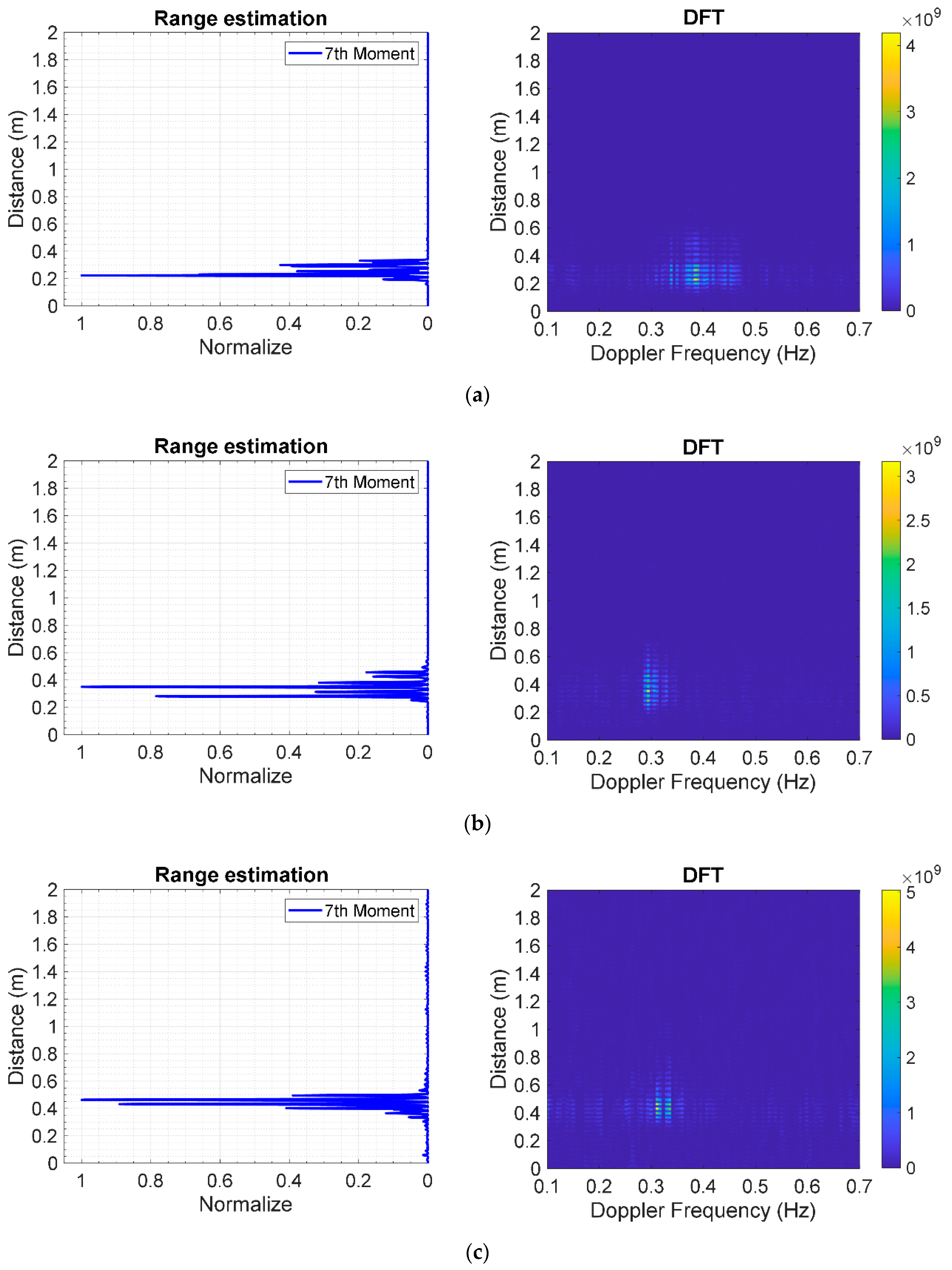
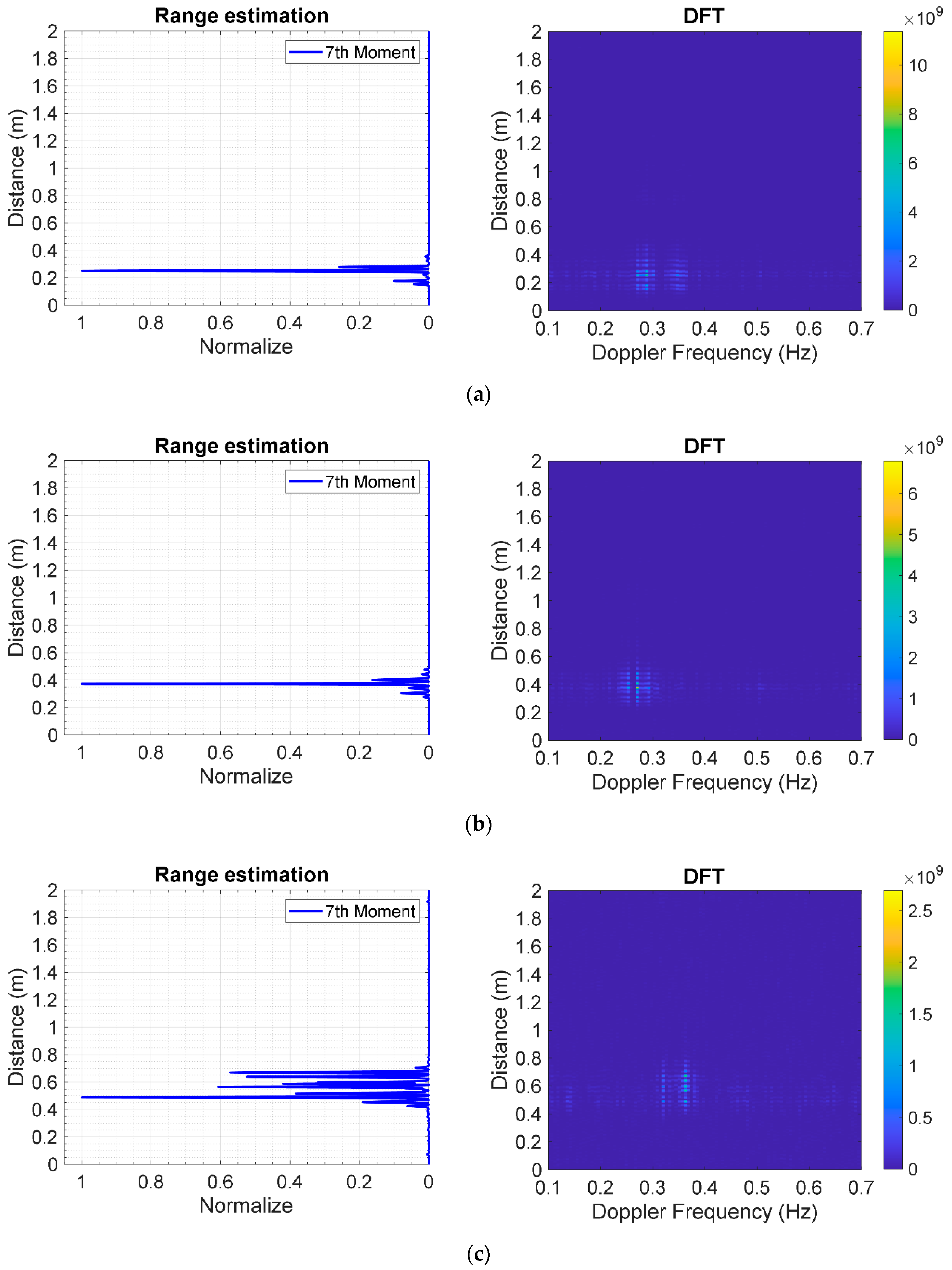
Figure 18a–c respectively shows the estimated range of the human subject in supine position under different thicknesses of stacked clay bricks: 9 (3 layers), 18 (6 layers), and 27 cm (9 layers). In range estimation, the statistical 7th moment is used to locate human subjects underneath the rubble. The estimated distances (range) between the radar antennas and the human subject are 22.33, 35.08, and 46.32 cm for 3, 6, and 9 layers of stacked bricks. Meanwhile, the corresponding distances, as measured by laser measuring device, are 24.5, 33.5, and 42.5 cm. The experimental and measured results are in good agreement, indicating the applicability of the IR-UWB radar system for human localization underneath the rubble.
Figure 19a–c respectively illustrate the estimated range of the human subject in prone position under different thicknesses of clay bricks: 9 (3 layers), 18 (6 layers), and 27 cm (9 layers). The estimated distances between the antennas and human subject are 25.18, 37.32, and 48.72 cm for 3, 6, and 9 layers of stacked bricks. The corresponding distances, as measured by laser measuring device, are 25.5, 34.5, and 43.5 cm. The experimental and measured results are in good agreement. As illustrated in Figure 18 and Figure 19, statistical 7th moment improves the range estimation performance of the IR-UWB radar system, vis-à-vis DFT.

6. Conclusions

This research proposes an FPGA scheme to generate an IR-UWB pulse based on four time-delay paths using LUT four-input XOR gate. The FPGA scheme consists of three parts: digital clock manager, delay path stratagem, and edge combiner. The IR-UWB radar system is designed to detect from respiration live humans buried underneath the rubble in the wake of an earthquake. The IR-UWB radar system is also capable of estimating the range to locate human subjects buried underneath. Discrete fast Fourier transform is utilized to detect the respiration in terms of Doppler frequency, and the statistical 7th moment is used to locate human subjects underneath the rubble. Experiments were carried out with human subjects lying underneath different layers of stacked clay bricks in supine and prone position. The results show that the IR-UWB radar system achieves a pulse duration of 540 ps and a bandwidth of 2.073 GHz (117 MHz–2.19 GHz, fractional bandwidth of 1.797). In respiration detection, the experimental results are in good agreement with the respiration sensor readings, indicating that the IR-UWB radar system is capable of human detection underneath the rubble. In addition, the estimated ranges of the human location buried underneath using the IR-UWB radar system are agreeable with those measured by a laser measuring device. In essence, the proposed technology could be further improved for rescue operation in the aftermath of an earthquake.

Author Contributions

Conceptualization, L.T.; methodology, L.T. and P.P.; validation, L.T. and P.P.; formal analysis, L.T. and P.P.; investigation, L.T. and P.P.; writing—original draft preparation, L.T.; writing—review and editing, L.T. and P.P.; funding acquisition, P.P. All authors have read and agreed to the published version of the manuscript.

Funding

This research was funded by Faculty of Engineering, King Mongkut’s Institute of Technology Ladkrabang, Bangkok, 10520, Thailand.

Acknowledgments

This research could not be success without technical supporting from BURN laboratory staff of KMITL. The most important is encouragement and other supporting from our parents and family.

Conflicts of Interest

The authors declare no conflict of interest.

References

  1. Guarnieri, M. The Early History of Radar [Historical]. IEEE Ind. Electron. Mag. 2010, 4, 36–42. [Google Scholar] [CrossRef]
  2. Miguelez, C.G.; Huyart, B.; Bergeault, E.; Jallet, L.P. New Automobile Radar Based on the Six-Port Phase/Frequency Discriminator. IEEE Trans. Veh. Technol. 2000, 49, 1416–1423. [Google Scholar] [CrossRef]
  3. Xu, S.; Baker, C.J.; Pooni, S. Range and Doppler Cell Migration in Wideband Automotive Radar. IEEE Trans. Veh. Technol. 2019, 68, 5527–5536. [Google Scholar] [CrossRef]
  4. Feng, Z.; Li, M.; Stolz, M.; Kunert, M.; Wiesbeck, W. Lane Detection with a High-Resolution Automotive Radar by Introducing a New Type of Road Marking. IEEE Trans. Intell. Transp. Syst. 2019, 20, 2430–2447. [Google Scholar] [CrossRef]
  5. Sim, H.; Lee, S.; Lee, B.; Kim, S. Road structure classification through artificial neural network for automotive radar systems. IET RadarSonar Navig. 2019, 13, 1010–1017. [Google Scholar] [CrossRef]
  6. Fernandez, M.G.; Lopez, Y.A.; Valdes, B.G.; Vaqueiro, Y.R.; Andres, F.L.; Garcia, A.P. Synthetic Aperture Radar Imaging System for Landmine Detection Using a Ground Penetrating Radar on Board a Unmanned Aerial Vehicle. IEEE Access 2018, 6, 45100–45112. [Google Scholar] [CrossRef]
  7. Sipos, D.; Gleich, D. A Lightweight and Low-Power UAV-Borne Ground Penetrating Radar Design for Landmine Detection. Sensors 2020, 20, 2234. [Google Scholar] [CrossRef] [Green Version]
  8. Gonzalez-Huici, M.A.; Catapano, I.; Soldovieri, F. A Comparative Study of GPR Reconstruction Approaches for Landmine Detection. IEEE J. Sel. Top. Appl. Earth Obs. Remote Sens. 2014, 7, 4869–4878. [Google Scholar] [CrossRef]
  9. Migliaccio, M.; Nunziata, F.; Montuori, A.; Li, X.; Pichel, W.G. A Multifrequency Polarimetric SAR Processing Chain to Observe Oil Fields in the Gulf of Mexico. IEEE Trans. Geosci. Remote Sens. 2011, 49, 4729–4737. [Google Scholar] [CrossRef]
  10. Buhari, M.D.; Tian, G.; Tiwari, R. Microwave-Based SAR Technique for Pipeline Inspection Using Autofocus Range-Doppler Algorithm. IEEE Sens. J. 2019, 19, 1777–1787. [Google Scholar] [CrossRef] [Green Version]
  11. Damini, A.; McDonald, M.; Haslam, G.E. X-band wideband experimental airborne radar for SAR, GMTI and maritime surveillance. IEE Proc. Radar Sonar Navig. 2003, 150, 305. [Google Scholar] [CrossRef]
  12. Reigber, A.; Scheiber, R.; Jager, M.; Prats-Iraola, P.; Hajnsek, I.; Jagdhuber, T.; Papathanassiou, K.P.; Nannini, M.; Aguilera, E.; Baumgartner, S.; et al. Very-High-Resolution Airborne Synthetic Aperture Radar Imaging: Signal Processing and Applications. Proc. IEEE 2013, 101, 759–783. [Google Scholar] [CrossRef] [Green Version]
  13. Gallego, A.-J.; Gil, P.; Pertusa, A.; Fisher, R.B. Segmentation of Oil Spills on Side-Looking Airborne Radar Imagery with Autoencoders. Sensors 2018, 18, 797. [Google Scholar] [CrossRef] [PubMed] [Green Version]
  14. Liu, L.; Liu, Z.; Barrowes, B.E. Through-Wall Bio-Radiolocation with UWB Impulse Radar: Observation, Simulation and Signal Extraction. IEEE J. Sel. Top. Appl. Earth Obs. Remote Sens. 2011, 4, 791–798. [Google Scholar] [CrossRef]
  15. Li, C.; Lubecke, V.M.; Boric-Lubecke, O.; Lin, J. A Review on Recent Advances in Doppler Radar Sensors for Noncontact Healthcare Monitoring. IEEE Trans. Microw. Theory Tech. 2013, 61, 2046–2060. [Google Scholar] [CrossRef]
  16. Droitcour, A.D.; Boric-Lubecke, O.V.; Lubecke, M.; Lin, J.; Kovacs, G.T.A. Range correlation and I/Q performance benefits in single-chip silicon Doppler radars for noncontact cardiopulmonary monitoring. IEEE Trans. Microw. Theory Tech. 2004, 52, 838–848. [Google Scholar] [CrossRef]
  17. Li, C.; Lin, J.; Xiao, Y. Robust Overnight Monitoring of Human Vital Signs by a Non-contact Respiration and Heartbeat Detector. In Proceedings of the 2006 International Conference of the IEEE Engineering in Medicine and Biology Society, New York, NY, USA, 30 August–3 September 2006. [Google Scholar]
  18. Li, C.; Ling, J.; Li, J.; Lin, J. Accurate Doppler Radar Noncontact Vital Sign Detection Using the RELAX Algorithm. IEEE Trans. Instrum. Meas. 2010, 59, 687–695. [Google Scholar]
  19. Lin, F.; Zhuang, Y.; Song, C.; Wang, A.; Li, Y.; Gu, C.; Li, C.; Xu, W. SleepSense: A Noncontact and Cost-Effective Sleep Monitoring System. IEEE Trans. Biomed. Circuits Syst. 2017, 11, 189–202. [Google Scholar] [CrossRef]
  20. Hong, H.; Zhang, L.; Gu, C.; Li, Y.; Zhou, G.; Zhu, X. Noncontact Sleep Stage Estimation Using a CW Doppler Radar. IEEE J. Emerg. Sel. Top. Circuits Syst. 2018, 8, 260–270. [Google Scholar] [CrossRef]
  21. Zhao, H.; Hong, H.; Miao, D.; Li, Y.; Zhang, H.; Zhang, Y.; Li, C.; Zhu, X. A Noncontact Breathing Disorder Recognition System Using 2.4-GHz Digital-IF Doppler Radar. IEEE J. Biomed. Health Inform. 2019, 23, 208–217. [Google Scholar] [CrossRef]
  22. Chuang, H.; Chen, Y.; Chen, K. Automatic clutter-canceler for microwave life-detection systems. IEEE Transactions on Instrumentation and Measurement. IEEE Trans. Instrum. Meas. 1991, 40, 747–750. [Google Scholar] [CrossRef] [Green Version]
  23. Chen, K.; Huang, Y.; Zhang, J.; Norman, A. Microwave life-detection systems for searching human subjects under earthquake rubble or behind barrier. IEEE Trans. Biomed. Eng. 2000, 47, 105–114. [Google Scholar] [CrossRef] [PubMed]
  24. Gennarelli, G.; Ludeno, G.; Soldovieri, F. Real-Time Through-Wall Situation Awareness Using a Microwave Doppler Radar Sensor. Remote Sens. 2016, 8, 621. [Google Scholar] [CrossRef] [Green Version]
  25. Baker, C.J.; Piper, S.O. Continuous Wave Radar. In Principles of Modern Radar: Radar Applications, 1st ed.; Melvin, W.L., Scheer, J.A., Eds.; Institution of Engineering and Technology: Stevenage, UK, 2013; Volume 3, pp. 17–85. [Google Scholar]
  26. Wang, F.; Horng, T.; Peng, K.; Jau, J.; Li, J.; Chen, C. Detection of Concealed Individuals Based on Their Vital Signs by Using a See-Through-Wall Imaging System With a Self-Injection-Locked Radar. IEEE Trans. Microw. Theory Tech. 2013, 61, 696–704. [Google Scholar] [CrossRef] [Green Version]
  27. Jia, Y.; Guo, Y.; Yan, C.; Sheng, H.; Cui, G.; Zhong, X. Detection and Localization for Multiple Stationary Human Targets Based on Cross-Correlation of Dual-Station SFCW Radars. Remote Sens. 2019, 11, 1428. [Google Scholar] [CrossRef] [Green Version]
  28. Liu, L.; Liu, S. Remote Detection of Human Vital Sign with Stepped-Frequency Continuous Wave Radar. IEEE J. Sel. Top. Appl. Earth Obs. Remote Sens. 2014, 7, 775–782. [Google Scholar] [CrossRef]
  29. Sisma, O.; Gaugue, A.; Liebe, C.; Ogier, J.M. UWB radar: Vision through a wall. Telecommun. Syst. 2008, 38, 53–59. [Google Scholar] [CrossRef]
  30. Fontana, R.J. Recent system applications of short-pulse ultra-wideband (UWB) technology. IEEE Trans. Microw. Theory Tech. 2004, 52, 2087–2104. [Google Scholar] [CrossRef]
  31. Li, J.; Zeng, Z.; Sun, J.; Liu, F. Through-Wall Detection of Human Being’s Movement by UWB Radar. IEEE Geosci. Remote Sens. Lett. 2012, 9, 1079–1083. [Google Scholar] [CrossRef]
  32. Immoreev, I.I.; Fedotov, D.V. Ultra wideband radar systems: Advantages and disadvantages. In Proceedings of the 2002 IEEE Conference on Ultra Wideband Systems and Technologies, Baltimore, MD, USA, 21–23 May 2002. [Google Scholar]
  33. Liang, F.; Qi, F.; An, Q.; Lv, H.; Chen, F.; Li, Z.; Wang, J. Detection of Multiple Stationary Humans Using UWB MIMO Radar. Sensors 2016, 16, 1922. [Google Scholar] [CrossRef] [Green Version]
  34. Dubey, R. Introduction to Embedded System Design Using Field Programmable Gate Arrays, 1st ed.; Springer Publishing Company: London, UK, 2009; pp. 10–12. [Google Scholar]
  35. Contreras-Medina, L.M.; Romero-Troncoso, R.J.; Millan-Almaraz, J.R.; Rodriguez-Donate, C. FPGA based multiple-channel vibration analyzer embedded system for industrial applications in automatic failure detection. In Proceedings of the 2008 International Symposium on Industrial Embedded Systems, Le Grande Motte, France, 25 July 2008. [Google Scholar]
  36. Vyas, S.; Kumar, N.G.; Zambreno, J.; Gill, C.; Cytron, R.; Jones, P. An FPGA-Based Plant-on-Chip Platform for Cyber-Physical System Analysis. IEEE Embed. Syst. Lett. 2014, 6, 4–7. [Google Scholar] [CrossRef]
  37. Cristo, A.; Fisher, K.; Gualtieri, J.; Pérez, R.M.; Martínez, P. Optimization of Processor-to-Hardware Module Communications on Spaceborne Hybrid FPGA-based Architectures. IEEE Embed. Syst. Lett. 2013, 5, 77–80. [Google Scholar] [CrossRef]
  38. Yang, Y.; Fathy, A.E. Development and Implementation of a Real-Time See-Through-Wall Radar System Based on FPGA. IEEE Trans. Geosci. Remote Sens. 2009, 47, 1270–1280. [Google Scholar] [CrossRef]
  39. Wang, Y.; Liu, Q.; Fathy, A.E. CW and Pulse–Doppler Radar Processing Based on FPGA for Human Sensing Applications. IEEE Trans. Geosci. Remote Sens. 2013, 51, 3097–3107. [Google Scholar] [CrossRef]
  40. Liang, C.; Liu, S.; Liu, S. A Calibrated Pulse Generator for Impulse-Radio UWB Applications. IEEE J. Solid-State Circuits 2006, 41, 2401–2407. [Google Scholar] [CrossRef]
  41. Wentzloff, D.D.; Chandrakasan, A.P. A 47pJ/pulse 3.1-to-5GHz All-Digital UWB Transmitter in 90nm CMOS. In Proceedings of the 2007 IEEE International Solid-State Circuits Conference. Digest of Technical Papers, San Francisco, CA, USA, 11–15 February 2007. [Google Scholar]
  42. Ryckaert, J.; Desset, C.; Fort, A.; Badaroglu, M.; De Heyn, V.; Wambacq, P.; Van der Plas, G.; Donnay, S.; Van Poucke, B.; Gyselinckx, B. Ultra-wide-band transmitter for low-power wireless body area networks: Design and evaluation. IEEE Trans. Circuits Syst. I Regul. Pap. 2005, 52, 2515–2525. [Google Scholar] [CrossRef]
  43. Park, Y.; Wentzloff, D.D. All-digital synthesizable UWB transmitter architectures. In Proceedings of the 2008 IEEE International Conference on Ultra-Wideband, Hannover, Germany, 10–12 September 2008. [Google Scholar]
  44. Tantiparimongkol, L.; Phasukkit, P. Experiment of UWB Pulse Generator using FPGA based on Delay Line-Based Pulse Generation for Radar Application. In Proceedings of the 2018 International Symposium on Multimedia and Communication Technology (ISMAC), Tottori, Japan, 29–31 August 2018. [Google Scholar]
  45. Tantiparimongkol, L.; Phasukkit, P. Designing of UWB Pulse Generation in FPGA Based on Delay Line Method for Human Range Through the Wall Detecting Application. In Proceedings of the 2019 16th International Conference on Electrical Engineering/Electronics, Computer, Telecommunications and Information Technology (ECTI-CON), Pattaya, Thailand, 10–13 July 2019. [Google Scholar]
  46. Ghavami, M.; Michael, L.B.; Haruyama, S.; Kohno, R. A Novel UWB Pulse Shape Modulation System. Wirel. Pers. Commun. 2002, 23, 105–120. [Google Scholar] [CrossRef]
  47. Ma, L.; Khorasani, K. Constructive feedforward neural networks using Hermite polynomial activation functions. IEEE Trans. Neural Netw. 2005, 16, 821–833. [Google Scholar] [CrossRef]
  48. Chen, X.; Kiaei, S. Monocycle shapes for ultra wideband system. In Proceedings of the 2002 IEEE International Symposium on Circuits and Systems, Phoenix-Scottsdale, AZ, USA, 26–29 May 2002. [Google Scholar]
  49. Virtex-6 Family Overview (DS150). Available online: https://www.xilinx.com/support/documentation/data_sheets/ds150.pdf (accessed on 9 May 2020).
  50. PlanAhead User Guide (UG632). Available online: https://www.xilinx.com/support/documentation/sw_manuals/xilinx14_7/PlanAhead_UserGuide.pdf (accessed on 5 May 2020).
  51. Venkatesh, S.; Anderson, C.R.; Rivera, N.V.; Buehrer, R.M. Implementation and analysis of respiration-rate estimation using impulse-based UWB. In Proceedings of the MILCOM 2005—2005 IEEE Military Communications Conference, Atlantic City, NJ, USA, 20 March 2006. [Google Scholar]
  52. Xu, Y.; Chen, J.; Dai, S.; Fang, G. Experimental Study of UWB Pulse Radar for Life Detection. In Proceedings of the 2011 First International Conference on Instrumentation, Measurement, Computer, Communication and Control, Beijing, China, 21–23 October 2011. [Google Scholar]
  53. Xu, Y.; Dai, S.; Wu, S.; Chen, J.; Fang, G. Vital Sign Detection Method Based on Multiple Higher Order Cumulant for Ultrawideband Radar. IEEE Trans. Geosci. Remote Sens. 2012, 50, 4. [Google Scholar] [CrossRef]
  54. Liang, X.; Zhang, H.; Fang, G.; Ye, S.; Gulliver, T.A. An Improved Algorithm for Through-Wall Target Detection Using Ultra-Wideband Impulse Radar. IEEE Access 2017, 5, 22101–22118. [Google Scholar] [CrossRef]
  55. Liang, X.; Lv, T.; Zhang, H.; Gao, Y.; Fang, G. Through-wall human being detection using UWB impulse radar. Eurasip J. Wirel. Commun. Netw. 2018, 2018, 46. [Google Scholar] [CrossRef] [Green Version]
  56. Rittiplang, A.; Phasukkit, P. UWB Radar for Multiple Human Detection through the Wall Based on Doppler Frequency and Variance Statistic. In Proceedings of the 2019 12th Biomedical Engineering International Conference (BMEiCON), Ubon Ratchathani, Thailand, 19–22 November 2019. [Google Scholar]
  57. Xu, Y.; Wu, S.; Chen, C.; Chen, J.; Fang, G. A Novel Method for Automatic Detection of Trapped Victims by Ultrawideband Radar. IEEE Trans. Geosci. Remote Sens. 2012, 50, 3132–3142. [Google Scholar] [CrossRef]
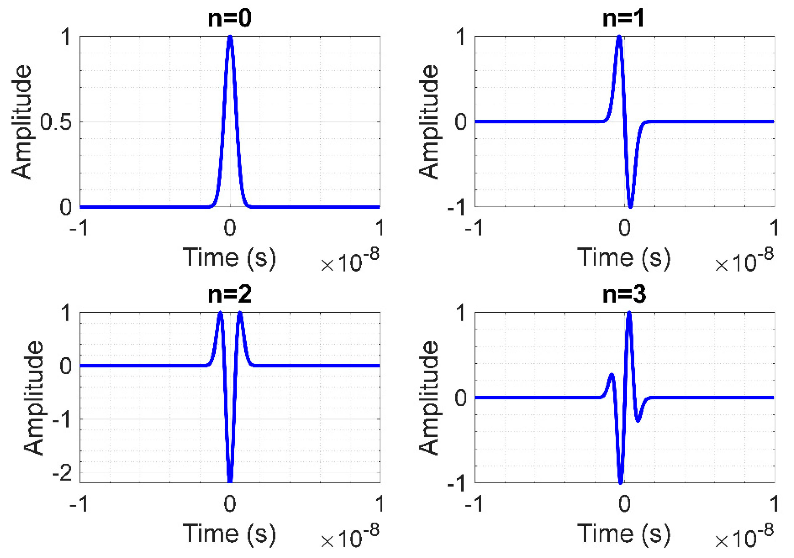
Figure 1. UWB pulse signals of 0th, 1st, 2nd, and 3rd order differential Gaussian distribution function.
Sensors 20 03750 g001
Figure 2. The proposed field programmable gate array (FPGA) scheme for IR-UWB pulse generation.
Sensors 20 03750 g002
Figure 3. Relationship between pulse repetition frequency and initial clock frequency of low-voltage differential signaling (LVDS) oscillator.
Sensors 20 03750 g003
Figure 4. The staggered time-delay stratagem with four delay paths.
Sensors 20 03750 g004
Figure 5. Edge combiner with look up table (LUT) algorithm as concurrent four-input XOR gate.
Sensors 20 03750 g005
Figure 6. Application of XOR to four staggered delay paths (X[0], X[1], X[2], and X[3]) for four narrow active pulses per cycle where z is the output of edge combiner.
Sensors 20 03750 g006
Figure 7. Reflected signals from human and solid object in fast time and slow time.
Sensors 20 03750 g007
Figure 8. The distance between antenna and human subject as a function of the movement amplitudes of the heart and respiration.
Sensors 20 03750 g008
Figure 9. Respiration rate and range estimation: (a) DFT doppler frequency; (b) statistical 7th moment.
Sensors 20 03750 g009
Figure 10. Schematic of IR-UWB pulse generation using the proposed FPGA scheme.
Sensors 20 03750 g010
Figure 11. Experimental setup for detection of human subject underneath layers of stacked clay bricks in supine and prone positions using the FPGA scheme.
Sensors 20 03750 g011
Figure 12. Schematic of IR-UWB pulse generation using FPGA scheme for detection of human subject underneath layers of stacked clay bricks.
Sensors 20 03750 g012
Figure 13. Waveform from ChipScope Pro Analyzer function.
Sensors 20 03750 g013
Figure 14. IR-UWB pulse generated by the FPGA scheme with pulse repetition frequency of 20 MHz using digital oscilloscope.
Sensors 20 03750 g014
Figure 15. Pulse duration and bandwidth of IR-UWB generated by the FPGA scheme.
Sensors 20 03750 g015
Figure 16. Respiratory frequency of a human subject in supine position under layers of stacked clay bricks, using IR-UWB radar system and respiration sensor: (a) 3 layers (9 cm); (b) 6 layers (18 cm); (c) 9 layers (27 cm).
Sensors 20 03750 g016
Figure 17. Respiratory frequency of a human subject in prone position under layers of stacked clay bricks, using IR-UWB radar system and respiration sensor: (a) 3 layers (9 cm); (b) 6 layers (18 cm); (c) 9 layers (27 cm).
Sensors 20 03750 g017
Figure 18. Statistical 7th-moment range estimation of a human subject in supine position under layers of stacked clay bricks using IR-UWB radar system: (a) 3 layers (9 cm); (b) 6 layers (18 cm); (c) 9 layers (27 cm).
Sensors 20 03750 g018
Figure 19. Statistical 7th-moment range estimation of a human subject in prone position under layers of stacked clay bricks using IR-UWB radar system: (a) 3 layers (9 cm); (b) 6 layers (18 cm); (c) 9 layers (27 cm).
Sensors 20 03750 g019
Table 1. Comparison between previous works on impulse-radio ultra-wideband (IR-UWB) technology and this current research.
SpecificsRef. [44]Ref. [45]Current Research
IR-UWB bandwidth1.6 GHz3.83 GHz2.19 GHz
Fractional bandwidth1.03321.797
Pulse repetition frequency (PRF)200 MHz,
400 MHz
20 MHz20 MHz
Signal amplitude611 mV432 mV456 mV
Human detection methodN/AArm swing motion
(macro-doppler)
Vital sign (respiration)
(micro-doppler)
Range estimation methodN/AStandard Deviation7th moment
Range validationN/AYesYes
Macro/Micro doppler validationN/ANoYes
(Respiration sensor)
Table 2. The specifications of experimental components.
ComponentsModel NameSpecification
Oscilloscope
(ADC)
Tektronix, TDS7404BDigital Phosphor Oscilloscope
(4 GHz, 20 GS/s)
FPGAXilinx,
Virtex 6-ML605
(XC6VLX240T)
Total logic cell: 241,152 cells
Technology process: 40 nm
Copper CMOS process
GPIBAgilent
Technologies,
82357B
USB/GPIB interface USB2.0, transfer rate over 850 KB/s
Power Amplifier
(PA)
Mini Circuits,
ZVE-8G
2 GHz–8 GHz, Gain = 30 dBm
Low Noise Amplifier
(LNA)
R&K-AA260-0S2 GHz–5 GHz, Gain = 26 dBm
Spectrum AnalyzerAnritsu,
MS8609A
Digital Mobile Radio Transmitter Tester,
9 kHz–13.2 GHz
Tx, Rx AntennasVivaldi antenna0.7 GHz–2.5 GHz, Gain = 11 dBi
Respiratory
measurement
sensor
Great Lakes
Neurotechnologies,
BioRadioTM
Wireless Biomedical monitor,
Chest Interface cables belt sensor.