Dry Electrodes for Human Bioelectrical Signal Monitoring


Abstract
1. Introduction
2. Invasive Microneedle Electrodes
2.1. Silicon Material-Based Microneedle Electrodes
2.2. Metallic Material-Based Microneedle Electrodes
2.3. Polymers Materials-Based Microneedle Electrodes
3. Surface Dry Electrodes
3.1. Metallic Material-Based Surface Dry Electrodes
3.2. Carbon Material-Based Surface Dry Electrodes
3.3. Polymer Material-Based Surface Dry Electrodes
4. Capacitive Electrodes
5. Summary and Prospects
Author Contributions
Funding
Acknowledgments
Conflicts of Interest
Appendix A

| References | Description | Materials | Type | Abstract | Technology |
|---|---|---|---|---|---|
| Griss [16] | Microneedles array electrodes coated with silver/silver chloride | Silicon, silver/silver chloride | Invasive EEG electrode | The lengths and diameters of microneedles range from 100 to 210 μm and 30 to 50 μm, respectively. The impedance remains about 18 kΩ at 10 Hz. | DRIE, wet etching, evaporation, thermal oxidation |
| Dias [18] | 54.7°-angle microneedles array and wireless system | Silicon, iridium oxide | Invasive EEG electrode | The electrode is composed by 16 microneedles that are fabricated by wet etching. | Wet etching, sputtering |
| Wang [19] | Rigid microneedles array on flexible substrate | Silicon, Parylene, Cr/Au | Invasive EEG electrode | The experimental results show that EII is lower than that of the conventional wet electrodes in EEG frequency domain. | LPCVD, wet etching, lift-off process, sputtering |
| O’Mahony [20] | Silicon -based Microneedle electrodes | Silicon, Ag | Invasive ECG electrode | The electrode consisted of a 5 × 5 arrangement of 300μm tall needles located at a pitch of 1.2 mm on a 7 mm × 7 mm die. | Anisotropic etching, thermally evaporation |
| Hsu [21] | Barbed microtip-based electrode arrays | Silicon, Ti/Ag | Invasive ECG electrode | KOH anisotropic wet etching was employed to form a standard pyramidal microtip array and isotropic etching was used to fabricate barbs on these microtips. | Anisotropic etching, isotropic etching |
| Matteucci [22] | Microneedle dry electrode built with deep X-ray lithography | Silicon, Au/Pd, Cu | Invasive EEG electrode | The electrode is high aspect ratio microelectrode with hollow microneedle arrays. | Deep X-ray lithography, Soft lithography, LIGA, pulsed laser deposition, evaporation |
| Zhang [23] | Silicon microneedles array with sharp tips | Silicon, PEDOT/PSS, PDMS | Invasive ECG electrode | Silicon microneedles are fixed on the PDMS substrate through bonding. PEDOT/PSS further decrease the EII. | Dicing saw, isotopic etching, dip coating |
| Forvi [24] | Microneedles-based dry electrodes | Silicon | Invasive EMG electrode | This dry electrode is fabricated by anisotropic wet etching technique. It is 10 mm square arrays hosting 8×8 pyramidal microneedles, the impedance value obtained after piercing is near to 5~10 kΩ. | Anisotropic etching |
| Lin [25] | Self-stabilized diamond-shaped microneedles array | Silicon, Au | Invasive EEG electrode | The length of microneedles is about 250 μm, the impedance of electrode is about 5 kΩ at 10 Hz. | Anisotropic etching |
| Guo [26] | Low melting point metal-based flexible 3D microneedles array | PDMS, metal | Invasive EEG electrode | The electrode has a flexible PDMS substrate, was based on low melting point metals, and it can be stretched to a maximum of 42% before it becomes non-conducting. | Phase transition method, 3D printing |
| Ren [27] | Flexible microneedle array electrode for bio-signal monitoring | Epoxy novolac resin, iron particles, Ti/Au, polyimide | Invasive ECG electrode | Microneedle array can be one-step drawn from the droplet array of curable magnetorheological fluid under the assist of external magnetic field. Ti/Au film was coated on the surface to insure the conductivity. | Magnetorheological drawing lithography, magnetron sputtering |
| Ren [28] | Microneedles array fabricated by thermal drawing | PLGA, Ti/Au | Invasive EEG electrode | The electrode is composed of 6 × 6 microneedles with an average height of about 500 µm. It presents less variation of impedance and better stability. | Thermal drawing method, magnetron sputtering |
| Srivastava [29] | SU-8 microneedles based dry electrodes for EEG | SU-8 negative photoresist, Au | Invasive ECG electrode | The electrode is fabricated by the UV maskless lithography in specially-made molds using a biocompatible polymer SU-8 photoresist. | Magnetron sputtering, UV maskless photolithography |
| Sun [30] | Composite Microneedle Array Electrode | Ti, SU-8 negative photoresist, Au | Invasive ECG electrode | The electrode consists of a 6 × 6 microneedles array with a height of 500 µm and a base diameter of 200 µm. | Spinning coating, sputter coating, laser cutting |
| References | Description | Materials | Type | Abstract | Technology |
|---|---|---|---|---|---|
| Liao [32] | Surface electrode with 17 spring contact probes | Stainless-steel, Au, Cu, BeCu | Surface EEG electrode | The lengths and diameters of microneedles range from 100 to 210 μm and 30 to 50 μm, respectively. The impedance remains about 18 kΩ at 10 Hz. | DRIE, wet etching, evaporation, thermal oxidation |
| Song [33] | Chitosan/Au-TiO2 nanotube-based dry electrodes for EEG | Chitosan (Ch), Au, TiO2 nanotube, Ti | Surface EEG electrode | This dry electrode is a Ch/Au-TiO2/Au-Ti multilayer film, the mean impedance values were approximately 169 ± 33.0kΩ at 2.15Hz and 67.4 ± 8.9 kΩ at 100 Hz. | Electrochemistry-based multi-potential step technology, electrochemical anodic oxidation method |
| Fiedler [34] | Novel multipin electrode cap system | Polyurethane, Ag/AgCl | Surface EEG electrode | The electrode consists of 24 single pins with circular tops of 1 mm in diameter and a height of 6 mm, the distances of the pins are 2.5 mm. | Not mentioned |
| Kappel [36] | A novel dry-contact ear-EEG electrode | Ti, IrO2, silver epoxy, acrylic plastic | Surface EEG electrode | This earphone electrode doesn’t need to measure on the hairy sites, but the change of the within-ear configuration resulted in low SNR. | Thermal oxidation, casting |
| Lee [38] | Personal earphone electrode for EEG | AgNW, CNT, PDMS. | Surface EEG electrode | The structures and elements of fabricated earphone that consists of AgNWs/CNTs/PDMS layer, a conductive interconnection layer covered by a gold layer, and supporting memory foam. | Not mentioned |
| Myers [39] | AgNWs dry electrode | AgNW, PDMS | Surface ECG electrode | AgNWs with average diameter of 90nm and length of 10~60 mm, and the conductivity of the electrode is over 50 S/m. | Casting |
| Cui [42] | Electrohydrodynamic printing AgNWs electrode | AgNW, PET, PDMS, paper | Surface ECG electrode | After post treatment, printed AgNWs showed an electrical conductivity as high as ∼5.6 × 10⁶ S/m. | Electrohydrodynamic printing |
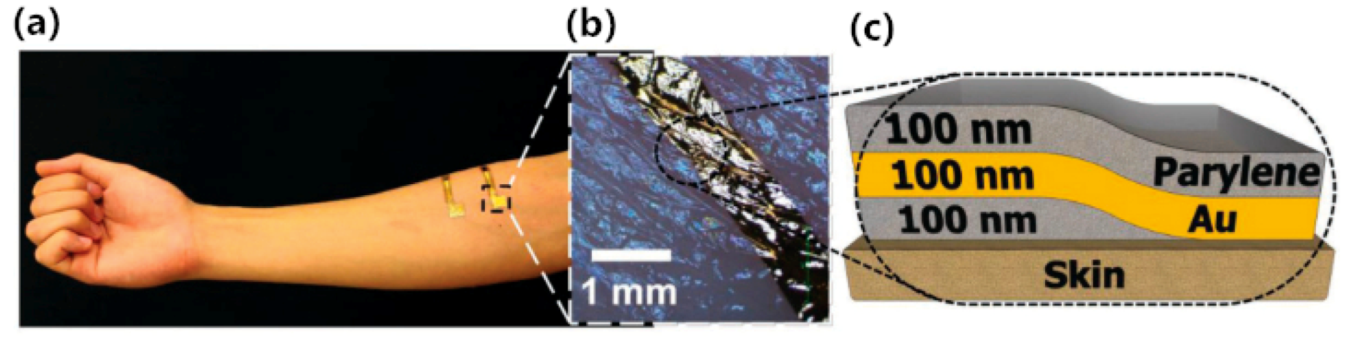
| Nawrocki [46] | Self-adhesive and ultra- conformable, sub-300 nm dry thin-film electrode | Parylene, Au | Surface EMG electrode | This dry electrode is sub-300 nm thin film electrode that is self-adhesive and conformable to complex skin surfaces. | Spin coating technique, thermally deposition |
| Gao [47] | Soft pin-shaped dry electrode with bristles | PDMS, CNT, PU, carbon fiber, Au | Surface EEG electrode | The diameter of the pedestal was 17 mm, and its thickness was 7 mm, the impedance was 10–100 kΩ order of magnitude. | Magnetic stirring, electroplating, casting |
| Lee [49] | CNT/PDMS conducting thin film electrode | CNT, PDMS | Surface ECG electrode | With 1.5 wt% the CNT dispersion, a flexible film was successfully tested for long-term usage as an ECG electrode. | Two-step dispersion method, spinning |
| Jung [50] | CNT/PDMS Composite Flexible Dry Electrodes | PDMS, CNT | Surface ECG electrode | The signal quality depended on the composition of the CNT/PDMS composite, and on the size of the electrode. | Two-step dispersion method, Casting |
| Peng [51] | Flexible micropillars electrode based on carbon nanotube/polymer hybrid | PDMS, CNT | Surface ECG electrode | The diameter and height of the single micropillar are 50 μm and 100 μm, respectively. Its EII is lower than that of the flat electrodes. | Spinning, UV photolithography, casting |
| Kim [53] | Dry electrode based on 1D−2D hybrid carbon nanocomposites | Graphene, CNT, PDMS | Surface ECG electrode | The electrode shows the lowest volume resistance (∼100 Ω·cm) at an optimized filler ratio with a normal adhesion force of ∼1.3 N/cm2 on human skin, which is comparable to that of commercial wet adhesives. | Casting |
| Yapici [61] | Graphene-clad textile electrodes | Graphene, textiles | Surface ECG electrode | The textiles electrode based on scalable and robust synthesis of conductive fabrics with graphene cladding. The EII ranges from 87.5 kΩ to 11.6 kΩ. | Dipping and coating, thermal treatment |
| Lou [62] | Flexible Graphene Electrodes | Graphene, PET, Ag, polyester fiber | Surface ECG electrode | The graphene textile electrode demonstrates comfortability, good biocompatibility, and high electrophysiological detection sensitivity. | Chemical vapor deposition, chemically reduction |
| Das [64] | Chemically reduced graphene oxide-based dry electrodes | Chemically reduced graphene oxide | Surface ECG electrode | The surface resistivity of the electrode is found 28 Ω/sq. | Chemically reduction, heating |
| Karim [65] | Inkjet-printed graphene-based textile | Graphene ink, textile | Surface ECG electrode | Inkjet printing reduces the sheet resistance of graphene-based printed e-textiles by three orders of magnitude compared with untreated textiles. | Inkjet deposition, chemically reduction |
| Salvo [70] | 3D printing dry electrodes for ECG/EEG recording | Acrylic-based resin, Au | Surface EEG electrode | Each needle is 3 mm high with base diameter of 600 μm and a tip diameter of about 100 μm, distance of 250 μm, and the impedance at 10 Hz is 62 kΩ | Sputtering, 3D printing |
| Kaitainen [71] | Liquid silicone rubber (LSR)-based dry bioelectrodes | Conductive liquid silicone rubber, Ti/Ag | Surface EEG electrode | Its impedance might be under 30 kΩ (uncoated) and under 10 kΩ (Ag-coated) at 1–1000 Hz. | magnetron sputtering |
| Krachunov [72] | 3D Printed Dry EEG Electrodes | Printed plastic, Ag/AgCl ink | Surface EEG electrode | Using low cost desktop 3D printers and off-the-shelf components for the fabrication, which allows quick and inexpensive electrode manufacturing and opens the possibility of creating electrodes customized for each user. | 3D printing |
| Lin [73] | Novel dry polymer foam electrodes | Conductive urethane material, conductive fabric, Ni/Cu | Surface EEG electrode | This foam electrode is fabricated by an electrically conductive polymer foam covered by a conductive fabric, the impedance at 10 Hz is 15 kΩ on the hairy site, 8 kΩ on hairless sites. | Not mention |
| Sinha [78] | Screen-Printed PEDOT:PSS Electrodes | PEDOT:PSS, textile | Surface ECG electrode | After five layers of PEDOT:PSS over an area give a sheet resistance of 5.6 Ω/sq. The SNR of the ECG signal is found to be 15.42 dB under dry skin conditions. | Screen-Printing |
| Castrillón [79] | PEDOT:PSS-based textile electrodes | PEDOT:PSS, textile materials | Surface ECG electrode | The textile electrodes are fabricated by treating different textile materials with PEDOT:PSS, there is no significant differences in acquiring ECG signals for different materials. | Dipping |
| De Camp [81] | Light-cured polymer electrodes | PEDOT, polymer | Surface EEG electrode | The electrode get cured by the application of blue light for a few seconds. The impedance was in a range from 10 Hz to 1000 Hz and results in values between 1.2~0.8 kΩ. | Light curing procedure |
| Bihar [82] | Inkjet-Printed PEDOT:PSS electrodes on paper | Paper, PEDOT: PSS | Surface ECG electrode | The electrode is fabricated by printing PEDOT:PSS on the commercial paper, which is eco-friendly and recyclable. | Inkjet printing |
| La [83] | Two-Layered and Stretchable e-Textile | Ag particles, fluoropolymer, PDMS, PU | Surface EMG electrode | A two-layered textile electrode is designed by controlled permeation of Ag particles and fluoropolymer composite ink into a porous textile. It has a good conductivity of about 3200 S/cm. | Printing, penetration |
| Jiang [84] | Polypyrrole-coated nonwoven fabric electrode | PET, nylon, ppy | Surface EMG electrode | This electrode using ppy-coated fabric sheet as conductive layer to realize sEMG acquisition. It can be sewn on the elastic band to guarantee close contact with the skin. | Dipping and coating |
| References | Description | Materials | Type | Abstract | Technology |
|---|---|---|---|---|---|
| Chen [98] | Novel Noncontact Dry Electrode With Adaptive Mechanical Design | Copper, plastic, steel spring | Capacitive EEG electrode | The basic scheme contains a metal plate electrode and an active circuit. The compression of the steel spring efficiently reduce the motion artifact. | Not mentioned |
| Baek [99] | Conductive Polymer Foam Capacitive Electrode | Polyolefine, polyurethane, Au, Ni/Cu | Capacitive EEG electrode | The size for the electrode of 36 mm in diameter by 17.71 mm in height. The impedances of the capacitive electrode is much higher than the Ag/AgCl electrode at a low frequency range. | Not mentioned |
References
- Xie, S.B. The Mystery of Bioelectricity; Science Popularization Press: Beijing, China, 1982; pp. 27–30. [Google Scholar]
- Acharya, U.R.; Sree, S.V.; Swapna, G.; Martis, R.J.; Suri, J.S. Automated EEG analysis of epilepsy: A review. Knowl.-Based Syst. 2013, 45, 147–165. [Google Scholar] [CrossRef]
- Cifrek, M.; Medved, V.; Tonkovic, S.; Ostojic, S. Surface EMG based muscle fatigue evaluation in biomechanics. Clin. Biomech. 2009, 24, 327–340. [Google Scholar] [CrossRef]
- Li, Y.J. Application of Eeg Analysis Method; Science Press: Beijing, China, 2009; pp. 4–7. [Google Scholar]
- Guo, S. Study on ECG Signal Denoising and Feature Recognition Algorithm. Master’s Thesis, Central South University, Changsha, China, 2009. [Google Scholar]
- Ruffini, G.; Dunne, S.; Farrés, E.; Marco-Pallarés, J.; Ray, C.; Mendoza, E.; Silva, R.; Grau, C. A dry electrophysiology electrode using CNT arrays. Sens. Actuators A 2006, 132, 34–41. [Google Scholar] [CrossRef]
- Prutchi, D.; Norris, M. Design and Development of Medical Electronic Instrumentation; John Wiley & Sons, Inc.: Hoboken, NJ, USA, 2005; pp. 1–40. [Google Scholar]
- Burke, M.J.; Gleeson, D.T. A micropower dry-electrode ECG preamplifier. IEEE Trans. Biomed. Eng. 2000, 47, 155–162. [Google Scholar] [CrossRef]
- Meziane, N.; Webster, J.G.; Attari, M.; Nimunkar, A.J. Dry electrodes for electrocardiography. Physiol. Meas. 2013, 34, R47–R69. [Google Scholar] [CrossRef]
- Chi, Y.M.; Jung, T.-P.; Cauwenberghs, G. Dry-contact and noncontact biopotential electrodes: Methodological review. IEEE Rev. Biomed. Eng. 2010, 3, 106–119. [Google Scholar] [CrossRef]
- Lopez-Gordo, M.; Morillo, D.; Valle, F. Dry EEG Electrodes. Sensors 2014, 14, 12847–12870. [Google Scholar] [CrossRef]
- Ren, L.; Liu, B.; Zhou, W.; Jiang, L.L. A Mini Review of Microneedle Array Electrode for Bio-Signal Recording: A Review. IEEE Sens. J. 2020, 20, 577–590. [Google Scholar] [CrossRef]
- Acar, G.; Ozturk, O.; Golparvar, A.J.; Elboshra, T.A.; Böhringer, K.; Yapici, M.K. Wearable and Flexible Textile Electrodes for Biopotential Signal Monitoring: A review. Electronics 2019, 8, 479–504. [Google Scholar] [CrossRef]
- Ma, G.; Wu, C. Microneedle, bio-microneedle and bio-inspired microneedle: A review. J. Control. Release 2017, 251, 11–23. [Google Scholar] [CrossRef]
- Donnelly, R.F.; Moffatt, K.; Alkilani, A.Z.; Vicente-Perez, E.M.; Barry, J.; McCrudden, M.T.; Woolfson, A.D. Hydrogel-forming microneedle arrays can be effectively inserted in skin by self-application: A pilot study centred on pharmacist intervention and a patient information leaflet. Pharm. Res. 2014, 31, 1989–1999. [Google Scholar] [CrossRef]
- Griss, P.; Enoksson, P.; Tolvanen-Laakso, H.K.; Merilainen, P.; Ollmar, S.; Stemme, G. Micromachined electrodes for biopotential measurements. J. Microelectromech. Syst. 2001, 10, 10–16. [Google Scholar] [CrossRef]
- Wang, Y.; Pei, W.; Guo, K.; Gui, Q.; Li, X.; Chen, H.; Yang, J. Dry electrode for the measurement of biopotential signals. Sci. Chin. Inf. Sci. 2011, 54, 2435–2442. [Google Scholar] [CrossRef]
- Dias, N.S.; Carmo, J.P.; Mendes, P.M.; Correia, J.H. Wireless instrumentation system based on dry electrodes for acquiring EEG signals. Med. Eng. Phys. 2012, 34, 972–981. [Google Scholar] [CrossRef]
- Wang, R.X.; Jiang, X.M.; Wang, W.; Li, Z.H. A microneedle electrode array on flexible substrate for long-term EEG monitoring. Sens. Actuators B-Chem. 2017, 244, 750–758. [Google Scholar] [CrossRef]
- O’Mahony, C.; Pini, F.; Blake, A.; Webster, C.; O’Brien, J.; McCarthy, K.G. Microneedle-based electrodes with integrated through-silicon via for biopotential recording. Sens. Actuators A 2012, 186, 130–136. [Google Scholar] [CrossRef]
- Hsu, L.S.; Tung, S.W.; Kuo, C.H.; Yang, Y.J. Developing Barbed Microtip-Based Electrode Arrays for Biopotential Measurement. Sensors 2014, 14, 12370–12386. [Google Scholar] [CrossRef]
- Matteucci, M.; Carabalona, R.; Casella, M.; Di Fabrizio, E.; Gramatica, F.; Di Rienzo, M.; Snidero, E.; Gavioli, L.; Sancrotti, M. Micropatterned dry electrodes for brain–computer interface. Microelectron. Eng. 2007, 84, 1737–1740. [Google Scholar] [CrossRef]
- Zhang, H.; Pei, W.; Chen, Y.; Guo, X.; Wu, X.; Yang, X.; Chen, H. A Motion Interference-Insensitive Flexible Dry Electrode. IEEE Trans. Biomed. Eng. 2016, 63, 1136–1144. [Google Scholar] [CrossRef]
- Forvi, E.; Bedoni, M.; Carabalona, R.; Soncini, M.; Mazzoleni, P.; Rizzo, F.; O’Mahony, C.; Morasso, C.; Cassara, D.G.; Gramatica, F. Preliminary technological assessment of microneedles-based dry electrodes for biopotential monitoring in clinical examinations. Sens. Actuators A 2012, 180, 177–186. [Google Scholar] [CrossRef]
- Chin-Teng, L.; Li-Wei, K.; Jin-Chern, C.; Jeng-Ren, D.; Ruey-Song, H.; Sheng-Fu, L.; Tzai-Wen, C.; Tzyy-Ping, J. Noninvasive Neural Prostheses Using Mobile and Wireless EEG. Proc. IEEE 2008, 96, 1167–1183. [Google Scholar] [CrossRef]
- Guo, S.; Lin, R.; Wang, L.; Lau, S.; Wang, Q.; Liu, R. Low melting point metal-based flexible 3D biomedical microelectrode array by phase transition method. Mater. Sci. Eng. C Mater. Biol. Appl. 2019, 99, 735–739. [Google Scholar] [CrossRef] [PubMed]
- Ren, L.; Jiang, Q.; Chen, Z.P.; Chen, K.Y.; Xu, S.J.; Gao, J.; Jiang, L.L. Flexible microneedle array electrode using magnetorheological drawing lithography for bio-signal monitoring. Sens. Actuators A 2017, 268, 38–45. [Google Scholar] [CrossRef]
- Ren, L.; Jiang, Q.; Chen, K.Y.; Chen, Z.P.; Pan, C.F.; Jiang, L.L. Fabrication of a Micro-Needle Array Electrode by Thermal Drawing for Bio-Signals Monitoring. Sensors 2016, 16, 13. [Google Scholar] [CrossRef]
- Srivastava, A.K.; Bhartia, B.; Mukhopadhyay, K.; Sharma, A. Long term biopotential recording by body conformable photolithography fabricated low cost polymeric microneedle arrays. Sens. Actuators A 2015, 236, 164–172. [Google Scholar] [CrossRef]
- Sun, Y.W.; Ren, L.; Jiang, L.L.; Tang, Y.; Liu, B. Fabrication of Composite Microneedle Array Electrode for Temperature and Bio-Signal Monitoring. Sensors 2018, 18, 12. [Google Scholar] [CrossRef]
- Kim, M.; Kim, T.; Kim, D.S.; Chung, W.K. Curved Microneedle Array-Based sEMG Electrode for Robust Long-Term Measurements and High Selectivity. Sensors 2015, 15, 16265–16280. [Google Scholar] [CrossRef]
- Liao, L.D.; Wang, I.J.; Chen, S.F.; Chang, J.Y.; Lin, C.T. Design, fabrication and experimental validation of a novel dry-contact sensor for measuring electroencephalography signals without skin preparation. Sensors 2011, 11, 5819–5834. [Google Scholar] [CrossRef]
- Song, Y.; Li, P.; Li, M.; Li, H.; Li, C.; Sun, D.; Yang, B. Fabrication of chitosan/Au-TiO2 nanotube-based dry electrodes for electroencephalography recording. Mater. Sci. Eng. C Mater. Biol. Appl. 2017, 79, 740–747. [Google Scholar] [CrossRef]
- Fiedler, P.; Griebel, S.; Pedrosa, P.; Fonseca, C.; Vaz, F.; Zentner, L.; Zanow, F.; Haueisen, J. Multichannel EEG with novel Ti/TiN dry electrodes. Sens. Actuators A 2015, 221, 139–147. [Google Scholar] [CrossRef]
- Pedrosa, P.; Alves, E.; Barradas, N.P.; Fiedler, P.; Haueisen, J.; Vaz, F.; Fonseca, C. TiNx coated polycarbonate for bio-electrode applications. Corros. Sci. 2012, 56, 49–57. [Google Scholar] [CrossRef]
- Kappel, S.L.; Rank, M.L.; Toft, H.O.; Andersen, M.; Kidmose, P. Dry-Contact Electrode Ear-EEG. IEEE Trans. Biomed. Eng. 2019, 66, 150–158. [Google Scholar] [CrossRef]
- Kidmose, P.; Looney, D.; Ungstrup, M.; Rank, M.L.; Mandic, D.P. A study of evoked potentials from ear-EEG. IEEE Trans. Biomed. Eng. 2013, 60, 2824–2830. [Google Scholar] [CrossRef]
- Lee, J.H.; Hwang, J.Y.; Zhu, J.; Hwang, H.R.; Lee, S.M.; Cheng, H.; Lee, S.H.; Hwang, S.W. Flexible Conductive Composite Integrated with Personal Earphone for Wireless, Real-Time Monitoring of Electrophysiological Signs. ACS Appl. Mater. Interfaces 2018, 10, 21184–21190. [Google Scholar] [CrossRef]
- Myers, A.C.; Huang, H.; Zhu, Y. Wearable silver nanowire dry electrodes for electrophysiological sensing. RSC Adv. 2015, 5, 11627–11632. [Google Scholar] [CrossRef]
- Weder, M.; Hegemann, D.; Amberg, M.; Hess, M.; Boesel, L.F.; Abacherli, R.; Meyer, V.R.; Rossi, R.M. Embroidered electrode with silver/titanium coating for long-term ECG monitoring. Sensors 2015, 15, 1750–1759. [Google Scholar] [CrossRef]
- Yao, S.S.; Myers, A.; Malhotra, A.; Lin, F.Y.; Bozkurt, A.; Muth, J.F.; Zhu, Y. A Wearable Hydration Sensor with Conformal Nanowire Electrodes. Adv. Healthc. Mater. 2017, 6, 8. [Google Scholar] [CrossRef]
- Cui, Z.; Han, Y.W.; Huang, Q.J.; Dong, J.Y.; Zhu, Y. Electrohydrodynamic printing of silver nanowires for flexible and stretchable electronics. Nanoscale 2018, 10, 6806–6811. [Google Scholar] [CrossRef]
- Qin, Q.; Li, J.; Yao, S.; Liu, C.; Huang, H.; Zhu, Y. Electrocardiogram of a Silver Nanowire Based Dry Electrode: Quantitative Comparison With the Standard Ag/AgCl Gel Electrode. IEEE Access 2019, 7, 20789–20800. [Google Scholar] [CrossRef]
- Xu, X.; Liu, Z.; He, P.; Yang, J. Screen printed silver nanowire and graphene oxide hybrid transparent electrodes for long-term electrocardiography monitoring. J. Phys. D Appl. Phys. 2019, 52, 45. [Google Scholar] [CrossRef]
- Choi, S.B.; Oh, M.S.; Han, C.J.; Kang, J.W.; Lee, C.R.; Lee, J.; Kim, J.W. Conformable, Thin, and Dry Electrode for Electrocardiography Using Composite of Silver Nanowires and Polyvinyl Butyral. Electron. Mater. Lett. 2019, 15, 267–277. [Google Scholar] [CrossRef]
- Nawrocki, R.A.; Jin, H.; Lee, S.; Yokota, T.; Sekino, M.; Someya, T. Self-Adhesive and Ultra-Conformable, Sub-300 nm Dry Thin-Film Electrodes for Surface Monitoring of Biopotentials. Adv. Funct. Mater. 2018, 28, 11. [Google Scholar] [CrossRef]
- Gao, K.P.; Yang, H.J.; Wang, X.L.; Yang, B.; Liu, J.Q. Soft pin-shaped dry electrode with bristles for EEG signal measurements. Sens. Actuators A 2018, 283, 348–361. [Google Scholar] [CrossRef]
- Zhang, Y.Y.; Sheehan, C.J.; Zhai, J.Y.; Zou, G.F.; Luo, H.M.; Xiong, J.; Zhu, Y.T.; Jia, Q.X. Polymer-Embedded Carbon Nanotube Ribbons for Stretchable Conductors. Adv. Mater. 2010, 22, 3027–3031. [Google Scholar] [CrossRef]
- Lee, J.H.; Nam, Y.W.; Jung, H.-C.; Baek, D.-H.; Lee, S.-H.; Hong, J.S. Shear induced CNT/PDMS conducting thin film for electrode cardiogram (ECG) electrode. BioChip J. 2012, 6, 91–98. [Google Scholar] [CrossRef]
- Jung, H.C.; Moon, J.H.; Baek, D.H.; Lee, J.H.; Choi, Y.Y.; Hong, J.S.; Lee, S.H. CNT/PDMS Composite Flexible Dry Electrodes for Long-Term ECG Monitoring. IEEE Trans. Biomed. Eng. 2012, 59, 1472–1479. [Google Scholar] [CrossRef]
- Peng, H.-L.; Liu, J.-Q.; Tian, H.-C.; Xu, B.; Dong, Y.-Z.; Yang, B.; Chen, X.; Yang, C.-S. Flexible dry electrode based on carbon nanotube/polymer hybrid micropillars for biopotential recording. Sens.Actuators A 2015, 235, 48–56. [Google Scholar] [CrossRef]
- Chlaihawi, A.A.; Narakathu, B.B.; Emamian, S.; Bazuin, B.J.; Atashbar, M.Z. Development of printed and flexible dry ECG electrodes. Sens. Bio-Sens. Res. 2018, 20, 9–15. [Google Scholar] [CrossRef]
- Kim, T.; Park, J.; Sohn, J.; Cho, D.; Jeon, S. Bioinspired, Highly Stretchable, and Conductive Dry Adhesives Based on 1D-2D Hybrid Carbon Nanocomposites for All-in-One ECG Electrodes. ACS Nano 2016, 10, 4770–4778. [Google Scholar] [CrossRef]
- Kim, K.H.; Hong, S.K.; Jang, N.S.; Ha, S.H.; Lee, H.W.; Kim, J.M. Wearable Resistive Pressure Sensor Based on Highly Flexible Carbon Composite Conductors with Irregular Surface Morphology. ACS Appl. Mater. Interfaces 2017, 9, 17500–17508. [Google Scholar] [CrossRef]
- Yamamoto, Y.; Yamamoto, D.; Takada, M.; Naito, H.; Arie, T.; Akita, S.; Takei, K. Efficient Skin Temperature Sensor and Stable Gel-Less Sticky ECG Sensor for a Wearable Flexible Healthcare Patch. Adv. Healthc. Mater. 2017, 6, 7. [Google Scholar] [CrossRef]
- Chi, M.; Zhao, J.J.; Dong, Y.; Wang, X.H. Flexible Carbon Nanotube-Based Polymer Electrode for Long-Term Electrocardiographic Recording. Materials 2019, 12, 11. [Google Scholar] [CrossRef]
- Polat, T.G.; Ateş, K.; Bilgin, S.; Duman, O.; Özen, Ş.; Tunç, S. Carbon nanotube, poly(3,4-ethylenedioxythiophene):poly(styrenesulfonate) and Ag nanoparticle doped gelatin based electro-active hydrogel systems. Colloids Surf. A 2019, 580, 123751. [Google Scholar] [CrossRef]
- Lee, E.; Cho, G. PU nanoweb-based textile electrode treated with single-walled carbon nanotube/silver nanowire and its application to ECG monitoring. Smart Mater. Struct. 2019, 28, 4. [Google Scholar] [CrossRef]
- Kang, B.-C.; Ha, T.-J. Wearable carbon nanotube based dry-electrodes for electrophysiological sensors. Jpn. J. Appl. Phys. 2018, 57, 5S. [Google Scholar] [CrossRef]
- Yapici, M.K.; Tamador, A.A.; Samad, Y.A.; Liao, K. Graphene-clad textile electrodes for electrocardiogram monitoring. Sens. Actuators B-Chem. 2015, 221, 1469–1474. [Google Scholar] [CrossRef]
- Lou, C.G.; Li, R.K.; Li, Z.P.; Liang, T.; Wei, Z.H.; Run, M.T.; Yan, X.B.; Liu, X.L. Flexible Graphene Electrodes for Prolonged Dynamic ECG Monitoring. Sensors 2016, 16, 12. [Google Scholar] [CrossRef]
- Ameri, S.K.; Ho, R.; Jang, H.W.; Tao, L.; Wang, Y.H.; Wang, L.; Schnyer, D.M.; Akinwande, D.; Lu, N.S. Graphene Electronic Tattoo Sensors. ACS Nano 2017, 11, 7634–7641. [Google Scholar] [CrossRef]
- Das, P.S.; Hossain, M.F.; Park, J.Y. Chemically reduced graphene oxide-based dry electrodes as touch sensor for electrocardiograph measurement. Microelectron. Eng. 2017, 180, 45–51. [Google Scholar] [CrossRef]
- Karim, N.; Afroj, S.; Malandraki, A.; Butterworth, S.; Beach, C.; Rigout, M.; Novoselov, K.S.; Casson, A.J.; Yeates, S.G. All inkjet-printed graphene-based conductive patterns for wearable e-textile applications. J. Mater. Chem. C 2017, 5, 11640–11648. [Google Scholar] [CrossRef]
- Yapici, M.K.; Alkhidir, T.E. Intelligent Medical Garments with Graphene-Functionalized Smart-Cloth ECG Sensors. Sensors 2017, 17, 12. [Google Scholar] [CrossRef]
- Qiao, Y.C.; Wang, Y.F.; Tian, H.; Li, M.R.; Jian, J.M.; Wei, Y.H.; Tian, Y.; Wang, D.Y.; Pang, Y.; Geng, X.S.; et al. Multilayer Graphene Epidermal Electronic Skin. ACS Nano 2018, 12, 8839–8846. [Google Scholar] [CrossRef]
- Stephens-Fripp, B.; Sencadas, V.; Mutlu, R.; Alici, G. Reusable Flexible Concentric Electrodes Coated With a Conductive Graphene Ink for Electrotactile Stimulation. Front. Bioeng. Biotechnol. 2018, 6, 179. [Google Scholar] [CrossRef]
- Laferriere, P.; Lemaire, E.D.; Chan, A.D.C. Surface Electromyographic Signals Using Dry Electrodes. IEEE Trans. Instrum. Meas. 2011, 60, 3259–3268. [Google Scholar] [CrossRef]
- Salvo, P.; Raedt, R.; Carrette, E.; Schaubroeck, D.; Vanfleteren, J.; Cardon, L. A 3D printed dry electrode for ECG/EEG recording. Sens. Actuators A 2012, 174, 96–102. [Google Scholar] [CrossRef]
- Kaitainen, S.; Kutvonen, A.; Suvanto, M.; Pakkanen, T.T.; Lappalainen, R.; Myllymaa, S. Liquid silicone rubber (LSR)-based dry bioelectrodes: The effect of surface micropillar structuring and silver coating on contact impedance. Sens. Actuators A 2014, 206, 22–29. [Google Scholar] [CrossRef]
- Krachunov, S.; Casson, A.J. 3D Printed Dry EEG Electrodes. Sensors 2016, 16, 10. [Google Scholar] [CrossRef]
- Lin, C.T.; Liao, L.D.; Liu, Y.H.; Wang, I.J.; Lin, B.S.; Chang, J.Y. Novel Dry Polymer Foam Electrodes for Long-Term EEG Measurement. IEEE Trans. Biomed. Eng. 2011, 58, 1200–1207. [Google Scholar]
- Norton, J.J.; Lee, D.S.; Lee, J.W.; Lee, W.; Kwon, O.; Won, P.; Jung, S.Y.; Cheng, H.; Jeong, J.W.; Akce, A.; et al. Soft, curved electrode systems capable of integration on the auricle as a persistent brain-computer interface. Proc. Natl. Acad. Sci. USA 2015, 112, 3920–3925. [Google Scholar] [CrossRef]
- Kim, D.H.; Lu, N.S.; Ma, R.; Kim, Y.S.; Kim, R.H.; Wang, S.D.; Wu, J.; Won, S.M.; Tao, H.; Islam, A.; et al. Epidermal Electronics. Science 2011, 333, 838–843. [Google Scholar] [CrossRef]
- Liu, Y.H.; Norton, J.J.S.; Qazi, R.; Zou, Z.N.; Ammann, K.R.; Liu, H.; Yan, L.Q.; Tran, P.L.; Jang, K.I.; Lee, J.W.; et al. Epidermal mechano-acoustic sensing electronics for cardiovascular diagnostics and human-machine interfaces. Sci. Adv. 2016, 2, 12. [Google Scholar] [CrossRef]
- Pani, D.; Dessi, A.; Saenz-Cogollo, J.F.; Barabino, G.; Fraboni, B.; Bonfiglio, A. Fully Textile, PEDOT: PSS Based Electrodes for Wearable ECG Monitoring Systems. IEEE Trans. Biomed. Eng. 2016, 63, 540–549. [Google Scholar] [CrossRef]
- Sinha, S.K.; Noh, Y.; Reljin, N.; Treich, G.M.; Hajeb-Mohammadalipour, S.; Guo, Y.; Chong, K.H.; Sotzing, G.A. Screen-Printed PEDOT: PSS Electrodes on Commercial Finished Textiles for Electrocardiography. ACS Appl. Mater. Interfaces 2017, 9, 37524–37528. [Google Scholar] [CrossRef] [PubMed]
- Castrillon, R.; Perez, J.J.; Andrade-Caicedo, H. Electrical performance of PEDOT: PSS-based textile electrodes for wearable ECG monitoring: A comparative study. Biomed. Eng. Online 2018, 17, 23. [Google Scholar] [CrossRef]
- Bihar, E.; Roberts, T.; Ismailova, E.; Saadaoui, M.; Isik, M.; Sanchez-Sanchez, A.; Mecerreyes, D.; Herve, T.; De Graaf, J.B.; Malliaras, G.G. Fully Printed Electrodes on Stretchable Textiles for Long-Term Electrophysiology. Adv. Mater. Technol. 2017, 2, 5. [Google Scholar] [CrossRef]
- de Camp, N.V.; Kalinka, G.; Bergeler, J. Light-cured polymer electrodes for non-invasive EEG recordings. Sci. Rep. 2018, 8, 14041. [Google Scholar] [CrossRef]
- Bihar, E.; Roberts, T.; Saadaoui, M.; Herve, T.; De Graaf, J.B.; Malliaras, G.G. Inkjet-Printed PEDOT: PSS Electrodes on Paper for Electrocardiography. Adv. Healthc. Mater. 2017, 6, 4. [Google Scholar] [CrossRef]
- La, T.G.; Qiu, S.; Scott, D.K.; Bakhtiari, R.; Kuziek, J.W.P.; Mathewson, K.E.; Rieger, J.; Chung, H.J. Two-Layered and Stretchable e-Textile Patches for Wearable Healthcare Electronics. Adv. Healthc. Mater. 2018, 7, e1801033. [Google Scholar] [CrossRef] [PubMed]
- Jiang, Y.; Togane, M.; Lu, B.; Yokoi, H. sEMG Sensor Using Polypyrrole-Coated Nonwoven Fabric Sheet for Practical Control of Prosthetic Hand. Front. Neurosci. 2017, 11, 33. [Google Scholar] [CrossRef]
- Posada-Quintero, H.; Noh, Y.; Eaton-Robb, C.; Florian, J.P.; Chon, K.H. Feasibility Testing of Hydrophobic Carbon Electrodes for Acquisition of Underwater Surface Electromyography Data. Ann. Biomed. Eng. 2018, 46, 1397–1405. [Google Scholar] [CrossRef]
- Lee, S.; Kim, M.-O.; Kang, T.; Park, J.; Choi, Y. Knit Band Sensor for Myoelectric Control of Surface EMG-Based Prosthetic Hand. IEEE Sens. J. 2018, 18, 8578–8586. [Google Scholar] [CrossRef]
- Pani, D.; Achilli, A.; Spanu, A.; Bonfiglio, A.; Gazzoni, M.; Botter, A. Validation of polymer-based screen-printed textile electrodes for surface EMG detection. IEEE Trans. Neural. Syst. Rehabil. Eng. 2019, 27, 1370–1377. [Google Scholar] [CrossRef]
- Yokus, M.A.; Jur, J.S. Fabric-Based Wearable Dry Electrodes for Body Surface Biopotential Recording. IEEE Trans. Biomed. Eng. 2016, 63, 423–430. [Google Scholar] [CrossRef] [PubMed]
- Ankhili, A.; Tao, X.; Cochrane, C.; Coulon, D.; Koncar, V. Washable and Reliable Textile Electrodes Embedded into Underwear Fabric for Electrocardiography (ECG) Monitoring. Materials 2018, 11, 2. [Google Scholar] [CrossRef]
- Lopez, A.; Richardson, P.C. Capacitive electrocardiographic and bioelectric electrodes. IEEE Trans. Biomed. Eng. 1969, 1, 99. [Google Scholar] [CrossRef] [PubMed]
- Chi, Y.M.; Maier, C.; Cauwenberghs, G. Ultra-High Input Impedance, Low Noise Integrated Amplifier for Noncontact Biopotential Sensing. IEEE J. Emerging Sel. Top. Circuits Syst. 2011, 1, 526–535. [Google Scholar] [CrossRef]
- Torfs, T.; Chen, Y.H.; Kim, H.; Yazicioglu, R.F. Noncontact ECG Recording System With Real Time Capacitance Measurement for Motion Artifact Reduction. IEEE Trans. Biomed. Circuits Syst. 2014, 8, 617–625. [Google Scholar] [CrossRef]
- Babusiak, B.; Borik, S.; Balogova, L. Textile electrodes in capacitive signal sensing applications. Measurement 2018, 114, 69–77. [Google Scholar] [CrossRef]
- Lim, Y.G.; Kim, K.K.; Park, K.S. ECG measurement on a chair without conductive contact. IEEE Trans. Biomed. Eng. 2006, 53, 956–959. [Google Scholar]
- Steffen, M.; Aleksandrowicz, A.; Leonhardt, S. Mobile noncontact monitoring of heart and lung activity. IEEE Trans. Biomed. Circuits Syst. 2007, 1, 250–257. [Google Scholar] [CrossRef]
- Varadan, V.K.; Rai, P.; Kumar, P.S.; Oh, S. e-bra With Nanosensors for Real Time Cardiac Health Monitoring and Smartphone Communication. J. Nanotechnol. Eng. 2011, 2, 2. [Google Scholar] [CrossRef]
- Varadan, V.K.; Rai, P.; Kumar, P.S.; Oh, S.; Kwon, H.; Mathur, G.N.; Varadan, V.K.; Agarwal, M.P. Smart healthcare textile sensor system for unhindered-pervasive health monitoring. Nanosens. Biosens. Info-Tech Sens. Syst. 2012, 8344, 83440E. [Google Scholar]
- Chen, Y.C.; Lin, B.S.; Pan, J.S. Novel Noncontact Dry Electrode With Adaptive Mechanical Design for Measuring EEG in a Hairy Site. IEEE Trans. Instrum. Meas. 2015, 64, 3361–3368. [Google Scholar] [CrossRef]
- Baek, H.J.; Lee, H.J.; Lim, Y.G.; Park, K.S. Conductive Polymer Foam Surface Improves the Performance of a Capacitive EEG Electrode. IEEE Trans. Biomed. Eng. 2012, 59, 3422–3431. [Google Scholar] [CrossRef]
- Lee, S.M.; Kim, J.H.; Park, C.; Hwang, J.Y.; Hong, J.S.; Lee, K.H.; Lee, S.H. Self-Adhesive and Capacitive Carbon Nanotube-Based Electrode to Record Electroencephalograph Signals From the Hairy Scalp. IEEE Trans. Biomed. Eng. 2016, 63, 138–147. [Google Scholar] [CrossRef]
- Lee, S.M.; Byeon, H.J.; Kim, B.H.; Lee, J.; Jeong, J.Y.; Lee, J.H.; Moon, J.H.; Park, C.; Choi, H.; Lee, S.H.; et al. Flexible and Implantable Capacitive Microelectrode for Bio-potential Acquisition. BioChip J. 2017, 11, 153–163. [Google Scholar] [CrossRef]
- Huang, Y.A.; Dong, W.T.; Zhu, C.; Xiao, L. Electromechanical Design of Self-Similar Inspired Surface Electrodes for Human-Machine Interaction. Complexity 2018. [Google Scholar] [CrossRef]
- Kim, D.W.; Baik, S.; Min, H.; Chun, S.; Lee, H.J.; Kim, K.H.; Lee, J.Y.; Pang, C. Highly Permeable Skin Patch with Conductive Hierarchical Architectures Inspired by Amphibians and Octopi for Omnidirectionally Enhanced Wet Adhesion. Adv. Funct. Mater. 2019, 29, 1807614. [Google Scholar] [CrossRef]
- Kier, W.M.; Smith, A.M. The structure and adhesive mechanism of octopus suckers. Integr. Comp. Biol. 2002, 42, 1146. [Google Scholar] [CrossRef]
- Tramacere, F.; Pugno, N.M.; Kuba, M.J.; Mazzolai, B. Unveiling the morphology of the acetabulum in octopus suckers and its role in attachment. Interface Focus. 2015, 5, 20140050. [Google Scholar] [CrossRef]
- Lang, U.; Naujoks, N.; Dual, J. Mechanical characterization of PEDOT:PSS thin films. Synth. Met. 2009, 159, 473–479. [Google Scholar] [CrossRef]
- Sun, Y.; Yu, X.; Berilla, J. An innovative non-invasive ECG sensor and comparison study with clinic system. In Proceedings of the 2013 39th Annual Northeast Bioengineering Conference, Syracuse, NY, USA, 5–7 April 2013. [Google Scholar]
- Wartzek, T.; Eilebrecht, B.; Lem, J.; Lindner, H.J.; Leonhardt, S.; Walter, M. ECG on the road: Robust and unobtrusive estimation of heart rate. IEEE Trans. Biomed. Eng. 2011, 58, 3112–3120. [Google Scholar] [CrossRef]
- Soroudi, A.; Hernandez, N.; Berglin, L.; Nierstrasz, V. Electrode placement in electrocardiography smart garments: A review. J. Electrocardiol. 2019, 57, 27–30. [Google Scholar] [CrossRef] [PubMed]
- Pino, E.J.; Arias, Y.; Aqueveque, P. Wearable EMG Shirt for Upper Limb Training. In Proceedings of the 40th Annual International Conference of the IEEE Engineering in Medicine and Biology Society (EMBC), Honolulu, HI, USA, 18–21 July 2018. [Google Scholar]
- Jeong, J.W.; Yeo, W.H.; Akhtar, A.; Norton, J.J.S.; Kwack, Y.J.; Li, S.; Jung, S.Y.; Su, Y.; Lee, W.; Xia, J.; et al. Materials and Optimized Designs for Human-Machine Interfaces via Epidermal Electronics. Adv. Mater. 2013, 25, 6839–6846. [Google Scholar] [CrossRef] [PubMed]


© 2020 by the authors. Licensee MDPI, Basel, Switzerland. This article is an open access article distributed under the terms and conditions of the Creative Commons Attribution (CC BY) license (http://creativecommons.org/licenses/by/4.0/).
Share and Cite
Fu, Y.; Zhao, J.; Dong, Y.; Wang, X. Dry Electrodes for Human Bioelectrical Signal Monitoring. Sensors 2020, 20, 3651. https://doi.org/10.3390/s20133651
Fu Y, Zhao J, Dong Y, Wang X. Dry Electrodes for Human Bioelectrical Signal Monitoring. Sensors. 2020; 20(13):3651. https://doi.org/10.3390/s20133651
Chicago/Turabian StyleFu, Yulin, Jingjing Zhao, Ying Dong, and Xiaohao Wang. 2020. "Dry Electrodes for Human Bioelectrical Signal Monitoring" Sensors 20, no. 13: 3651. https://doi.org/10.3390/s20133651
APA StyleFu, Y., Zhao, J., Dong, Y., & Wang, X. (2020). Dry Electrodes for Human Bioelectrical Signal Monitoring. Sensors, 20(13), 3651. https://doi.org/10.3390/s20133651