Neural Network Self-Tuning Control for a Piezoelectric Actuator


Abstract
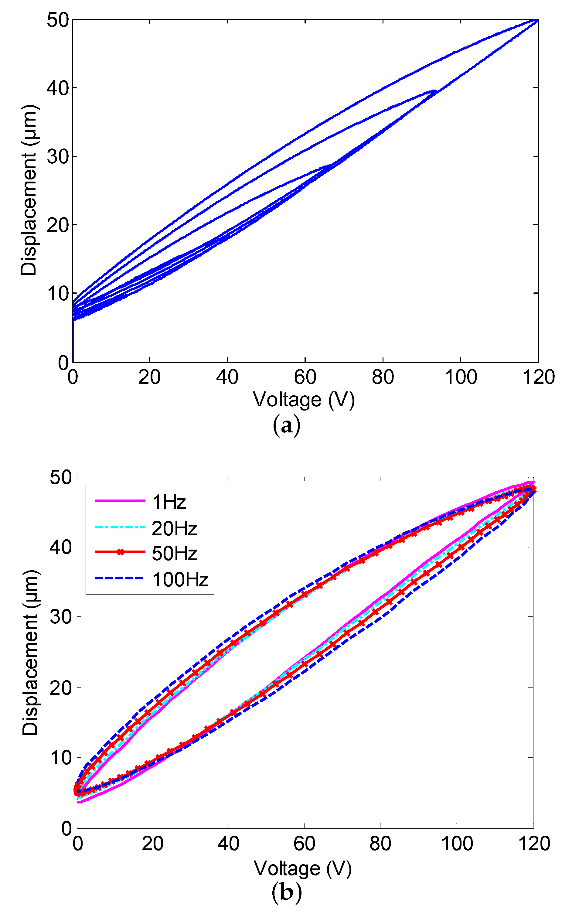
1. Introduction
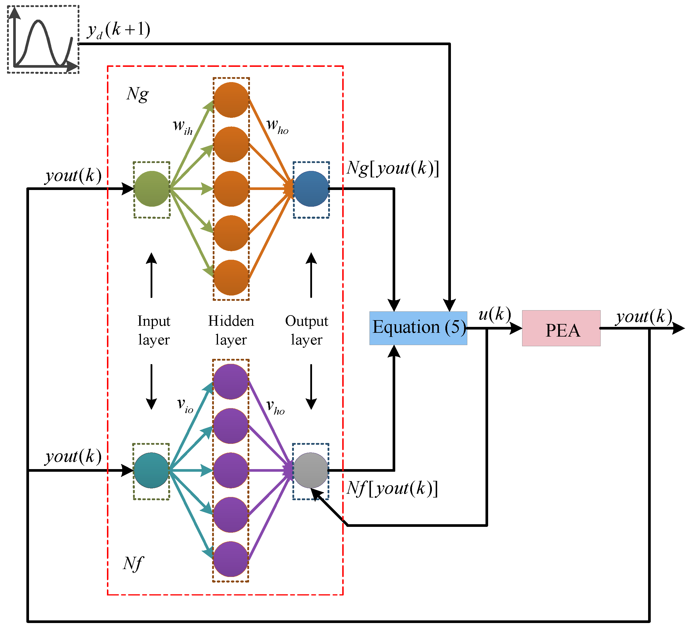
2. Controller Design
2.1. Design Philosophy
2.2. Neural Network Identifiers and
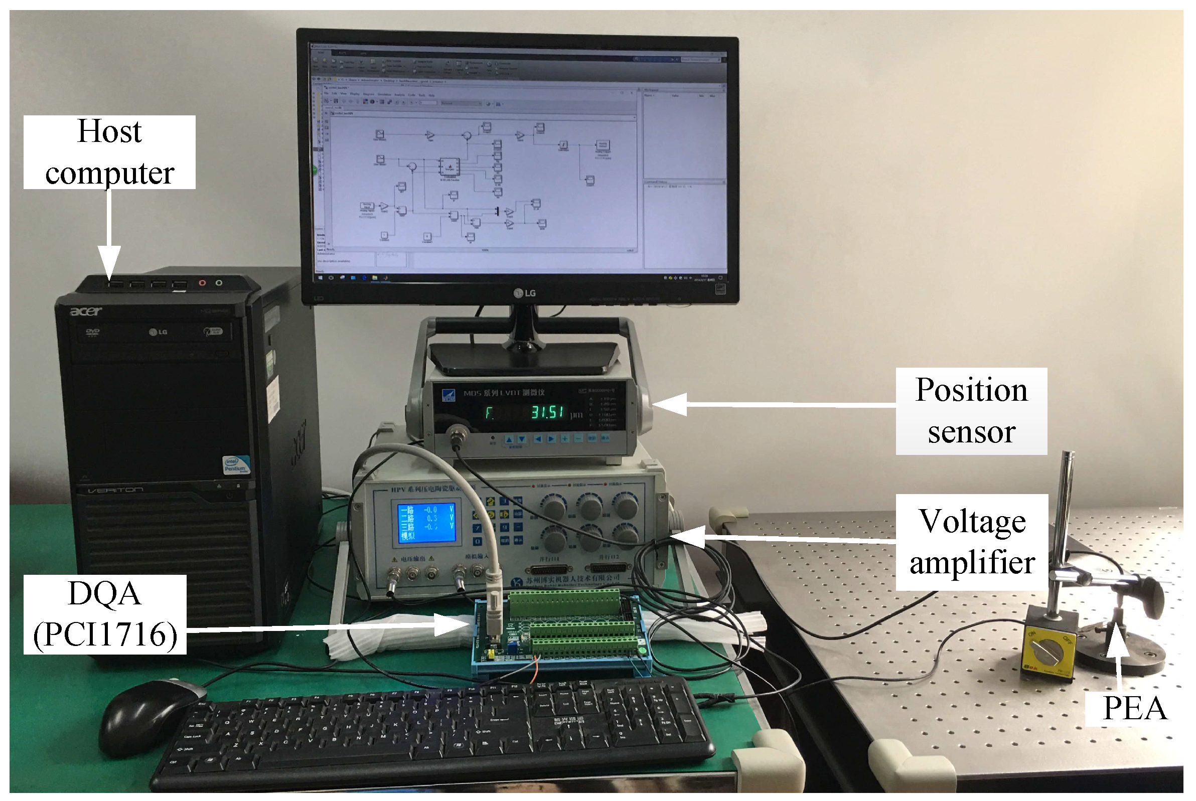
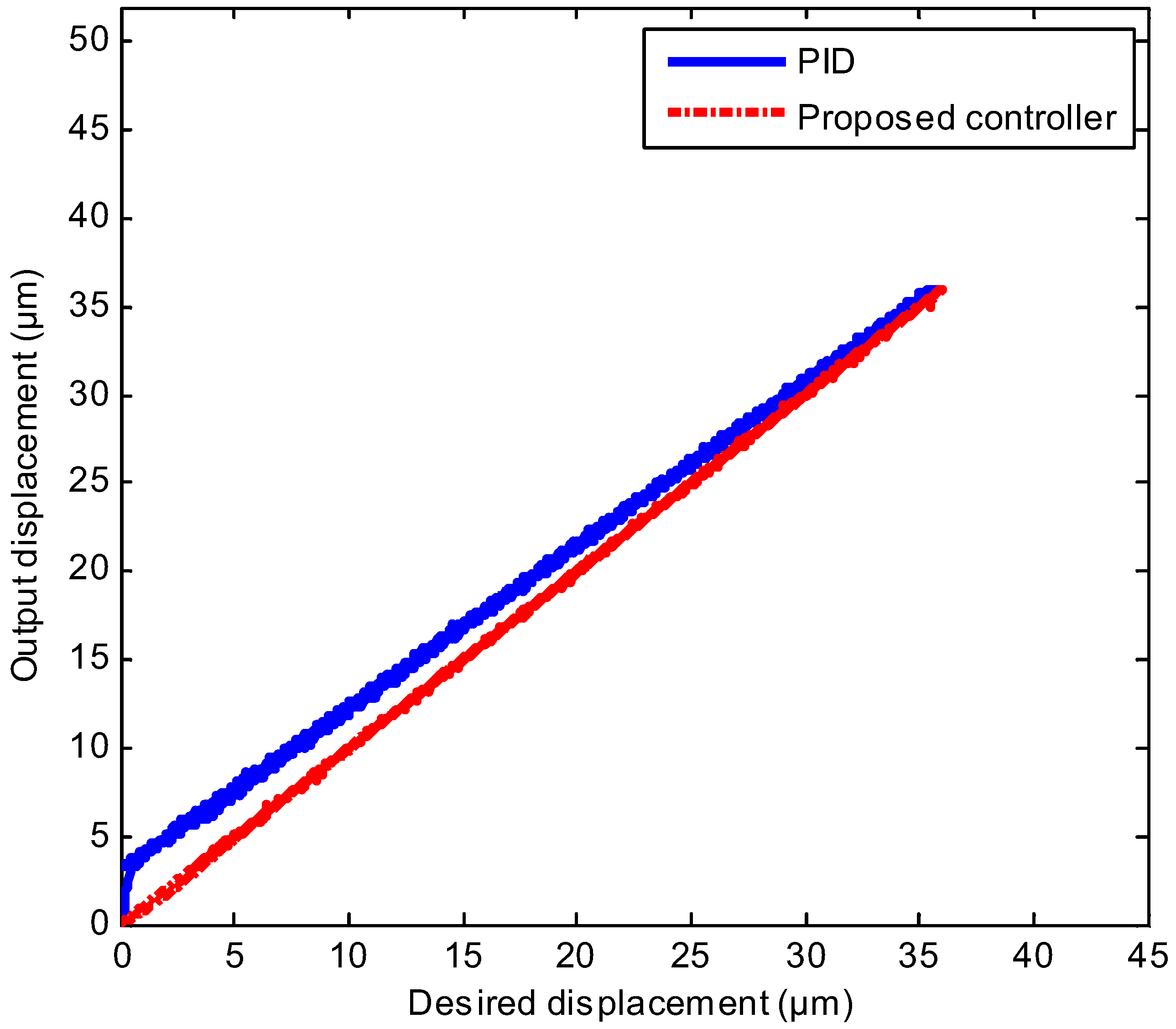
3. Experimental Study
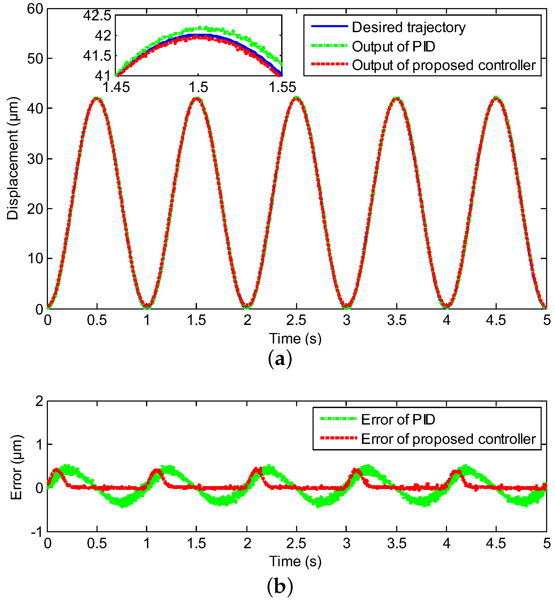
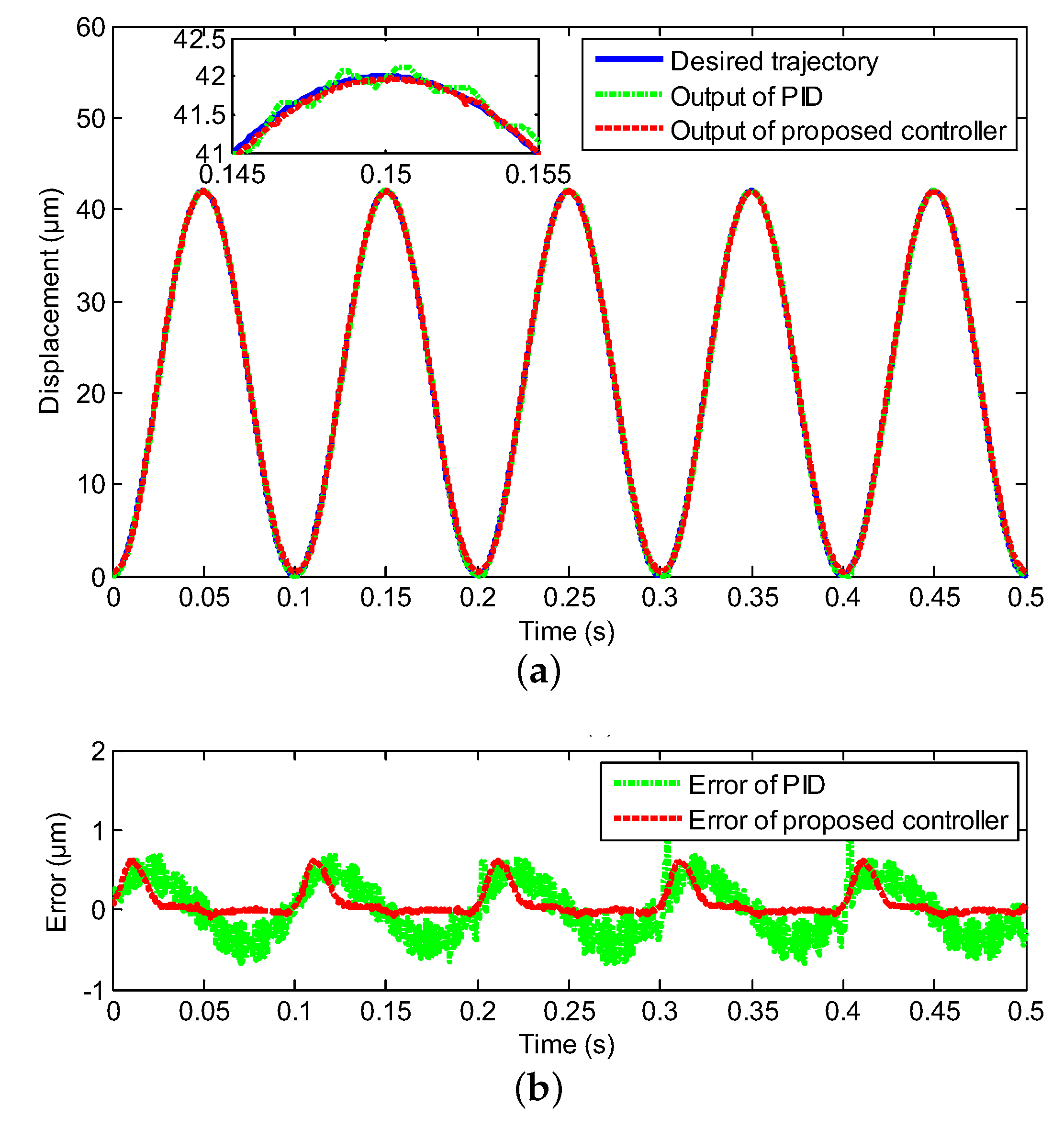
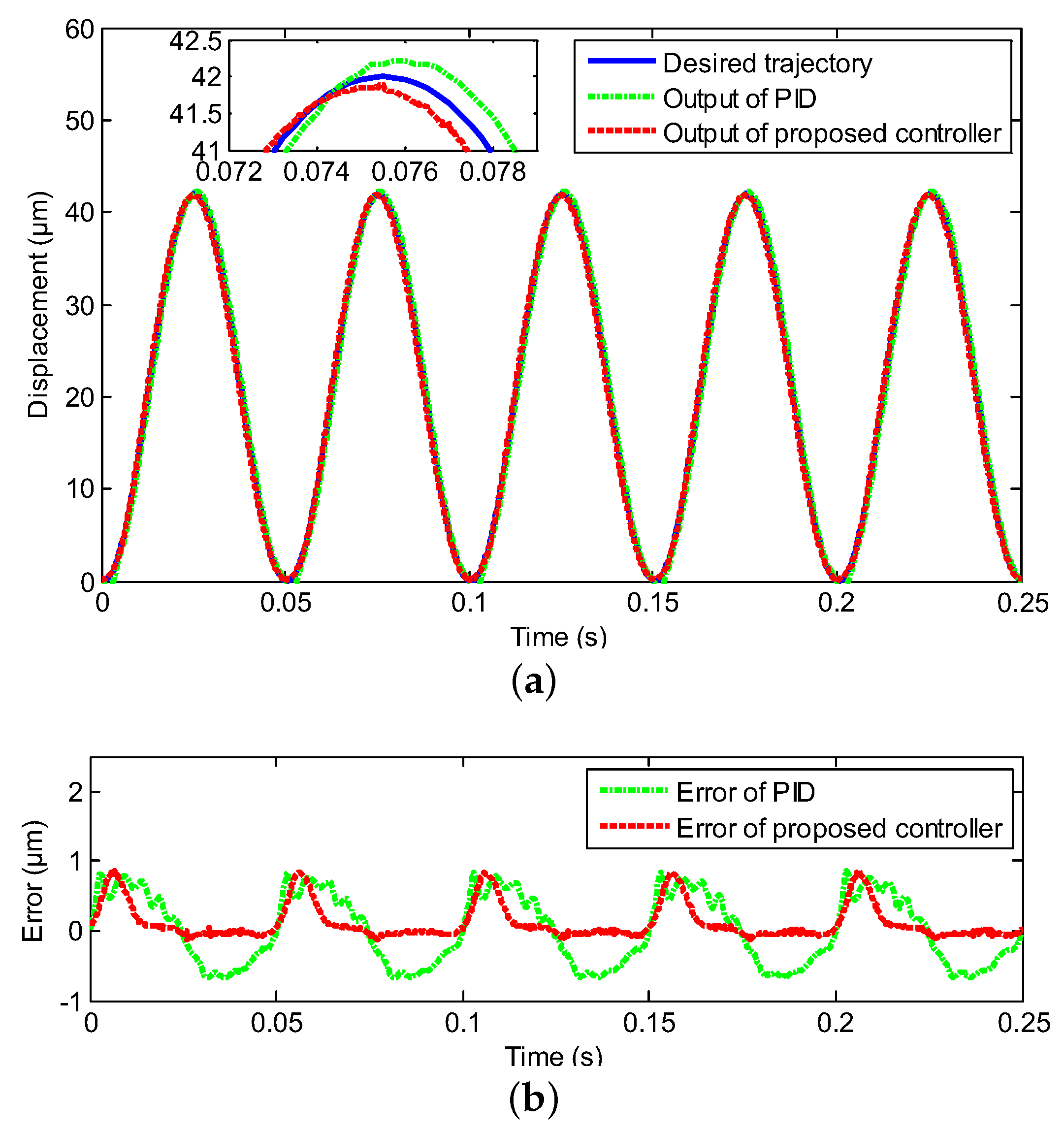
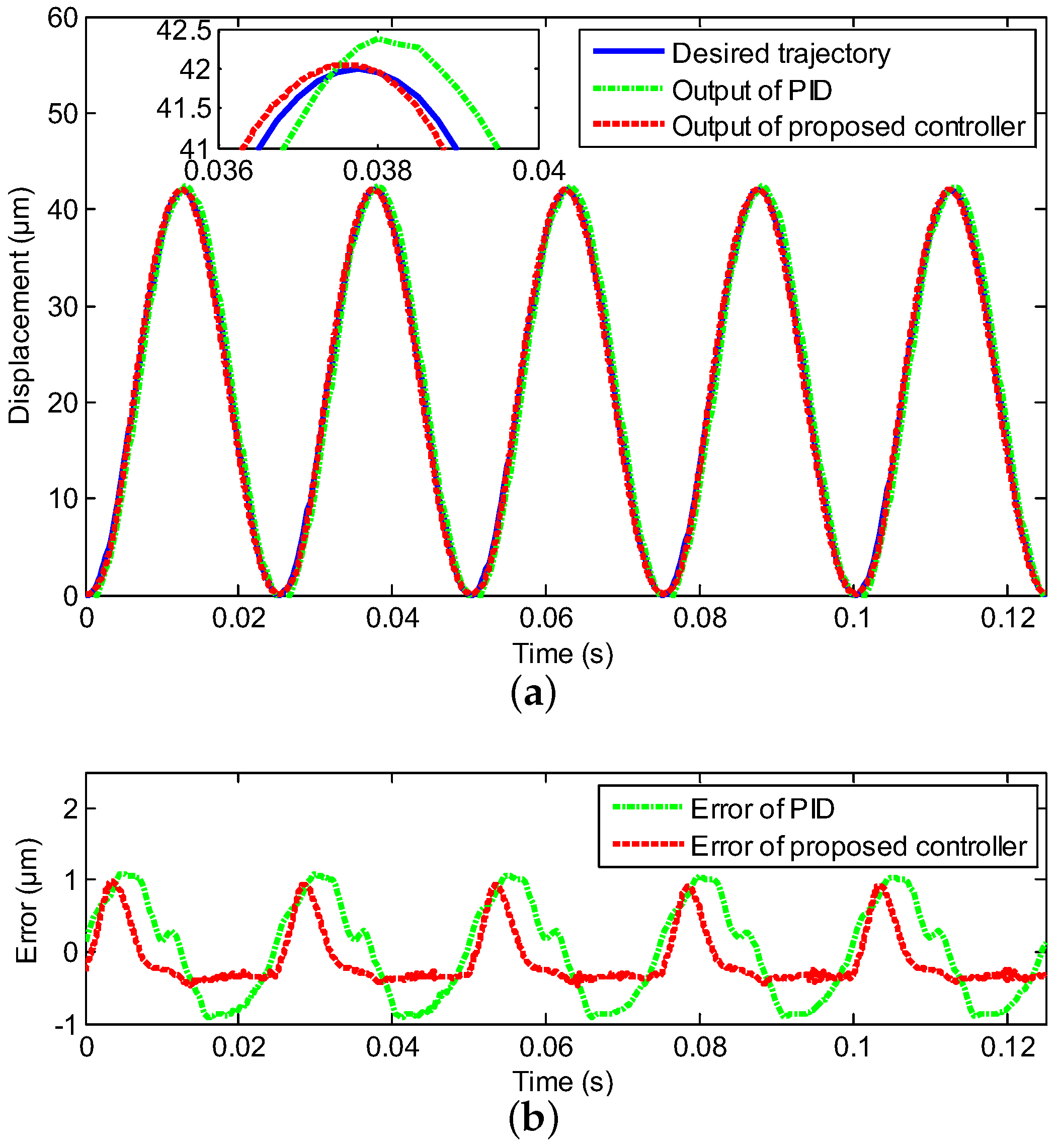
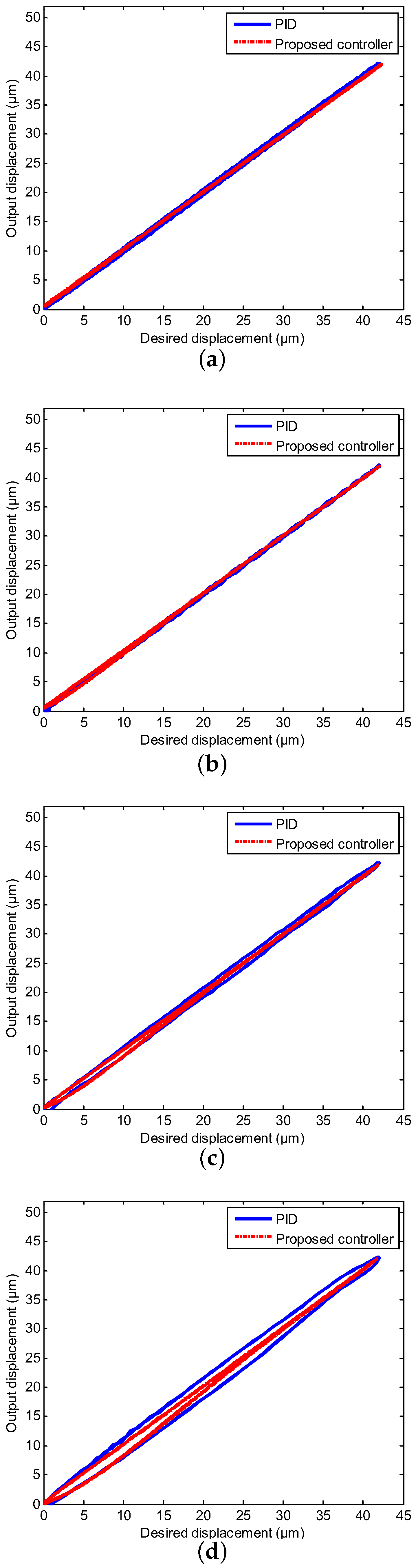
3.1. Tracking of Sinusoidal Trajectories with Diverse Frequencies
3.2. Tracking of Mixed Triangular Trajectory
4. Conclusions
Author Contributions
Funding
Conflicts of Interest
References
- Zhang, X.; Chen, X.; Zhu, G.; Su, C.Y. Output feedback adaptive motion control and its experimental verification for time-delay nonlinear systems with asymmetric hysteresis. IEEE Trans. Ind. Electron. 2020, 67, 6824–6834. [Google Scholar] [CrossRef]
- Zhang, X.; Wang, Y.; Chen, X.; Su, C.Y.; Li, Z.; Wang, C.; Peng, Y. Decentralized adaptive neural approximated inverse control for a class of large-scale nonlinear hysteretic systems with time delays. IEEE Trans. Syst. Man Cybern.-Syst. 2018, 49, 2424–2437. [Google Scholar] [CrossRef]
- Xu, R.; Zhang, X.; Guo, H.; Zhou, M. Sliding mode tracking control with perturbation estimation for hysteresis nonlinearity of piezo-actuated stages. IEEE Access 2018, 6, 2840538. [Google Scholar] [CrossRef]
- Wong, P.K.; Xu, Q.; Vong, C.M.; Wong, H.C. Rate-dependent hysteresis modeling and control of a piezostage using online support vector machine and relevance vector machine. IEEE Trans. Ind. Electron. 2012, 59, 1988–2001. [Google Scholar] [CrossRef]
- Cheng, L.; Liu, W.; Hou, Z.G.; Huang, T.; Yu, J.; Tan, M. An adaptive Takagi–Sugeno fuzzy model based predictive controller for piezoelectric actuators. IEEE Trans. Ind. Electron. 2017, 64, 3048–3058. [Google Scholar] [CrossRef]
- Leang, K.K.; Devasia, S. Design of hysteresis-compensating iterative learning control for piezo-positioners: Application to atomic force microscopes. Mechatronics 2006, 16, 141–158. [Google Scholar] [CrossRef]
- Ho, S.T.; Jan, S.J. A piezoelectric motor for precision positioning applications. Precis. Eng. 2016, 43, 285–293. [Google Scholar] [CrossRef]
- Avci, E.; Hattori, T.; Kamiyama, K.; Kojima, M.; Horade, M.; Mae, Y.; Arai, T. Piezo-actuated parallel mechanism for biological cell release at high speed. Biomed. Microdevices 2015, 17, 98. [Google Scholar] [CrossRef]
- Xiao, S.; Li, Y. Modeling and high dynamic compensating the rate-dependent hysteresis of piezoelectric actuators via a novel modified inverse Preisach model. IEEE Trans. Contr. Syst. Technol. 2013, 21, 1549–1557. [Google Scholar] [CrossRef]
- Zhang, X.; Wang, Y.; Wang, C.; Su, C.Y.; Li, Z.; Chen, X. Adaptive estimated inverse output-feedback quantized control for piezoelectric positioning stage. IEEE Trans. Cybern 2019, 49, 2106–2118. [Google Scholar] [CrossRef]
- Ge, P.; Jouaneh, M. Tracking control of a piezoceramic actuator. IEEE Trans. Contr. Syst. Technol. 1996, 4, 209–216. [Google Scholar]
- Gu, G.Y.; Zhu, L.M.; Su, C.Y.; Ding, H.; Fatikow, S. Modeling and control of piezo-actuated nanopositioning stages: A survey. IEEE Trans. Autom. Sci. Eng. 2014, 13, 313–332. [Google Scholar] [CrossRef]
- Yu, Y.; Zhang, C.; Zhou, M. NARMAX model based hysteresis modeling of magnetic shape memory alloy actuators. IEEE Trans. Nanotechnol. 2020, 19, 1–4. [Google Scholar] [CrossRef]
- Xu, R.; Zhou, M. A self-adaption compensation control for hysteresis nonlinearity in piezo-actuated stages based on Pi-sigma fuzzy neural network. Smart Mater. Struct. 2018, 27, 045002. [Google Scholar] [CrossRef]
- Nguyen, P.B.; Choi, S.B.; Song, B.K. A new approach to hysteresis modelling for a piezoelectric actuator using Preisach model and recursive method with an application to open-loop position tracking control. Sens. Actuators A-Phys. 2018, 270, 136–152. [Google Scholar] [CrossRef]
- Gu, G.Y.; Zhu, L.M.; Su, C.Y. Modeling and compensation of asymmetric hysteresis nonlinearity for piezoceramic actuators with a modified Prandtl–Ishlinskii model. IEEE Trans. Ind. Electron. 2014, 61, 1583–1595. [Google Scholar] [CrossRef]
- Yang, M.J.; Li, C.X.; Gu, G.Y.; Zhu, L.M. Modeling and compensating the dynamic hysteresis of piezoelectric actuators via a modified rate-dependent Prandtl–Ishlinskii model. Smart Mater. Struct. 2015, 24, 125006. [Google Scholar] [CrossRef]
- Zhou, M.; Xu, R.; Zhang, Q.; Wang, Z.; Zhao, Y. Hybrid Control Method of Magnetically Controlled Shape Memory Alloy Actuator Based on Inverse Prandtl-Ishlinskii Model. J. Electr. Eng. Technol. 2016, 11, 1457–1465. [Google Scholar] [CrossRef]
- Li, Z.; Shan, J.; Gabbert, U. Inverse compensation of hysteresis using Krasnoselskii-Pokrovskii model. IEEE-ASME T. Mech. 2018, 23, 966–971. [Google Scholar] [CrossRef]
- Rakotondrabe, M. Bouc–Wen modeling and inverse multiplicative structure to compensate hysteresis nonlinearity in piezoelectric actuators. IEEE Trans. Autom. Sci. Eng. 2011, 8, 428–431. [Google Scholar] [CrossRef]
- Wang, Y.; Zhang, C.; Wu, Z.; Gao, W.; Zhou, M. A hopfield neural network based Bouc-Wen model for magnetic shape memory alloy actuator. AIP Adv. 2020, 10, 015212. [Google Scholar] [CrossRef]
- Lin, C.J.; Lin, P.T. Tracking control of a biaxial piezo-actuated positioning stage using generalized Duhem model. Comput. Math. Appl. 2012, 64, 766–787. [Google Scholar] [CrossRef]
- Zhou, M.; Yang, P.; Wang, J.; Gao, W. Adaptive sliding mode control based on Duhem model for piezoelectric actuators. IETE Tech. Rev. 2016, 33, 557–568. [Google Scholar] [CrossRef]
- Xu, Q.; Wong, P.K. Hysteresis modeling and compensation of a piezostage using least squares support vector machines. Mechatronics 2011, 21, 1239–1251. [Google Scholar] [CrossRef]
- Zhou, M.; Wang, Y.; Xu, R.; Zhang, Q.; Zhu, D. Feed-forward control for magnetic shape memory alloy actuators based on the radial basis function neural network model. J. Appl. Biomater. Func. 2017, 15, 25–30. [Google Scholar] [CrossRef]
- Zhou, M.; Zhang, Q. Hysteresis model of magnetically controlled shape memory alloy based on a PID neural network. IEEE Trans. Magn. 2015, 51, 1–4. [Google Scholar]
- Al-Ghanimi, A.; Zheng, J.; Man, Z. A fast non-singular terminal sliding mode control based on perturbation estimation for piezoelectric actuators systems. Int. J. Control 2017, 90, 480–491. [Google Scholar] [CrossRef]
- Ming, M.; Ling, J.; Feng, Z.; Xiao, X. A model prediction control design for inverse multiplicative structure based feedforward hysteresis compensation of a piezo nanopositioning stage. Int. J. Precis. Eng. Man. 2018, 19, 1699–1708. [Google Scholar] [CrossRef]
- Chen, Z.; Zheng, J.; Zhang, H.T.; Ding, H. Tracking of piezoelectric actuators with hysteresis: A nonlinear robust output regulation approach. Int. J. Robust Nonlin. 2017, 27, 2610–2626. [Google Scholar] [CrossRef]
- Gu, G.Y.; Zhu, L.M.; Su, C.Y. High-precision control of piezoelectric nanopositioning stages using hysteresis compensator and disturbance observer. Smart Mater. Struct. 2014, 23, 105007. [Google Scholar] [CrossRef]
- Ounissi, A.; Yakoub, K.; Kaddouri, A.; Abdessemed, R. Robust adaptive displacement tracking control of a piezo-actuated stage. In Proceedings of the 2017 6th International Conference on Systems and Control (ICSC), Batna, Algeria, 7–9 May 2017. [Google Scholar]
- Xu, R.; Zhou, M. Sliding mode control with sigmoid function for the motion tracking control of the piezo-actuated stages. Electron. Lett. 2016, 53, 75–77. [Google Scholar] [CrossRef]
- Shan, Y.; Leang, K.K. Accounting for hysteresis in repetitive control design: Nanopositioning example. Automatica 2012, 48, 1751–1758. [Google Scholar] [CrossRef]
- Tsai, M.S.; Chen, J.S. Robust tracking control of a piezoactuator using a new approximate hysteresis model. J. Dyn. Syst.-Trans. ASME 2003, 125, 96–102. [Google Scholar] [CrossRef]
- Peng, J.Y.; Chen, X.B. Integrated PID based sliding mode state estimation and control for piezoelectric actuators. IEEE-ASME Trans. Mechatron. 2014, 19, 88–99. [Google Scholar] [CrossRef]
- Asif, A.R.; Waris, A.; Gilani, S.O.; Jamil, M.; Ashraf, H.; Shafique, M.; Niazi, I.K. Performance Evaluation of Convolutional Neural Network for Hand Gesture Recognition Using EMG. Sensors 2020, 20, 1642. [Google Scholar] [CrossRef] [PubMed]
- Elkatatny, S.; Al-AbdulJabbar, A.; Abdelgawad, K. A New Model for Predicting Rate of Penetration Using an Artificial Neural Network. Sensors 2020, 20, 2058. [Google Scholar] [CrossRef] [PubMed]
- Chu, Z.; Zhu, D.; Yang, S.X. Observer based adaptive neural network trajectory tracking control for remotely operated vehicle. IEEE Trans. Neural Netw. Learn. 2017, 28, 1633–1645. [Google Scholar] [CrossRef]
- Zhang, C.; Yu, Y.; Wang, Y.; Zhou, M. Takagi-Sugeno fuzzy neural network hysteresis modeling for magnetic shape memory alloy actuator based on modified bacteria foraging algorithm. Int. J. Fuzzy Syst. 2020, 22, 1314–1329. [Google Scholar] [CrossRef]
- Svečko, R.; Kusić, D. Feedforward neural network position control of a piezoelectric actuator based on a BAT search algorithm. Expert Syst. Appl. 2015, 42, 5416–5423. [Google Scholar] [CrossRef]
- Lin, F.J.; Shieh, H.J.; Huang, P.K. Adaptive wavelet neural network control with hysteresis estimation for piezo-positioning mechanism. IEEE Trans. Neural Netw. 2006, 17, 432–444. [Google Scholar] [CrossRef]
- Kauppinen, M.; Röning, J. Software based neural network assisted movement compensation for nanoresolution piezo actuators. In Intelligent Robots and Computer Vision XXIX: Algorithms and Techniques, 2nd ed.; SPIE: Burlingame, CA, USA, 2012; Volume 8301, p. 830102. [Google Scholar]
- Tseng, C.L.; Wang, S.Y.; Chien, S.C.; Chang, C.Y. Development of a self-tuning TSK-fuzzy speed control strategy for switched reluctance motor. IEEE Trans. Power Electron. 2011, 27, 2141–2152. [Google Scholar] [CrossRef]
- Zamani, A.A.; Tavakoli, S.; Etedali, S. Control of piezoelectric friction dampers in smart base-isolated structures using self-tuning and adaptive fuzzy proportional–derivative controllers. J. Intell. Mater. Syst. Struct. 2017, 28, 1287–1302. [Google Scholar] [CrossRef]
- Hernández-Alvarado, R.; García-Valdovinos, L.G.; Salgado-Jiménez, T.; Gómez-Espinosa, A.; Fonseca-Navarro, F. Neural network based self-tuning PID control for underwater vehicles. Sensors 2016, 16, 1429. [Google Scholar] [CrossRef] [PubMed]
- Tran, T.T.; Ha, C. Self-tuning proportional double derivative-like neural network controller for a quadrotor. Int. J. Aeronaut. Space 2018, 19, 976–985. [Google Scholar] [CrossRef]
- Liu, V.T. Self-tuning Neuro-PID controller for piezoelectric actuator. Adv. Sci. Lett. 2012, 14, 141–145. [Google Scholar] [CrossRef]
- Jie, D.G.; Sun, L.N.; Qu, D.S.; Wang, L.; Cai, H.G. Fuzzy-reasoning based self-tuning PID control for piezoelectric micro-displacement system. J. Harbin Inst. Technol. 2005, 37, 145–147. [Google Scholar]
- Chen, F.C. Back-propagation neural networks for nonlinear self-tuning adaptive control. IEEE Control Syst. Mag. 1990, 10, 44–48. [Google Scholar] [CrossRef]


| Basic Properties | Values | Units |
|---|---|---|
| Dimension | 7 × 7 × 42 | mm |
| Nominal displacement | 50 ± 10% | m |
| Maximum push force | 1800 | N |
| Stiffness | 36 | N/m |
| Capacitance | 6.9 ± 20% | F |
| Input | PID | Proposed Controller |
|---|---|---|
| Frequencies | (RMSE (m)/MAXE (%)) | (RMSE (m)/MAXE (%)) |
| 1 Hz | 0.2223/2.04 | 0.1133/1.02 |
| 10 Hz | 0.3136/2.77 | 0.2431/1.26 |
| 20 Hz | 0.4788/2.51 | 0.2545/1.85 |
| 40 Hz | 0.5283/3.29 | 0.3148/2.45 |
© 2020 by the authors. Licensee MDPI, Basel, Switzerland. This article is an open access article distributed under the terms and conditions of the Creative Commons Attribution (CC BY) license (http://creativecommons.org/licenses/by/4.0/).
Share and Cite
Li, W.; Zhang, C.; Gao, W.; Zhou, M. Neural Network Self-Tuning Control for a Piezoelectric Actuator. Sensors 2020, 20, 3342. https://doi.org/10.3390/s20123342
Li W, Zhang C, Gao W, Zhou M. Neural Network Self-Tuning Control for a Piezoelectric Actuator. Sensors. 2020; 20(12):3342. https://doi.org/10.3390/s20123342
Chicago/Turabian StyleLi, Wenjun, Chen Zhang, Wei Gao, and Miaolei Zhou. 2020. "Neural Network Self-Tuning Control for a Piezoelectric Actuator" Sensors 20, no. 12: 3342. https://doi.org/10.3390/s20123342
APA StyleLi, W., Zhang, C., Gao, W., & Zhou, M. (2020). Neural Network Self-Tuning Control for a Piezoelectric Actuator. Sensors, 20(12), 3342. https://doi.org/10.3390/s20123342