Performance Analysis of Ground Target Detection Utilizing Beidou Satellite Reflected Signals

Abstract
:1. Introduction
2. Detection Method
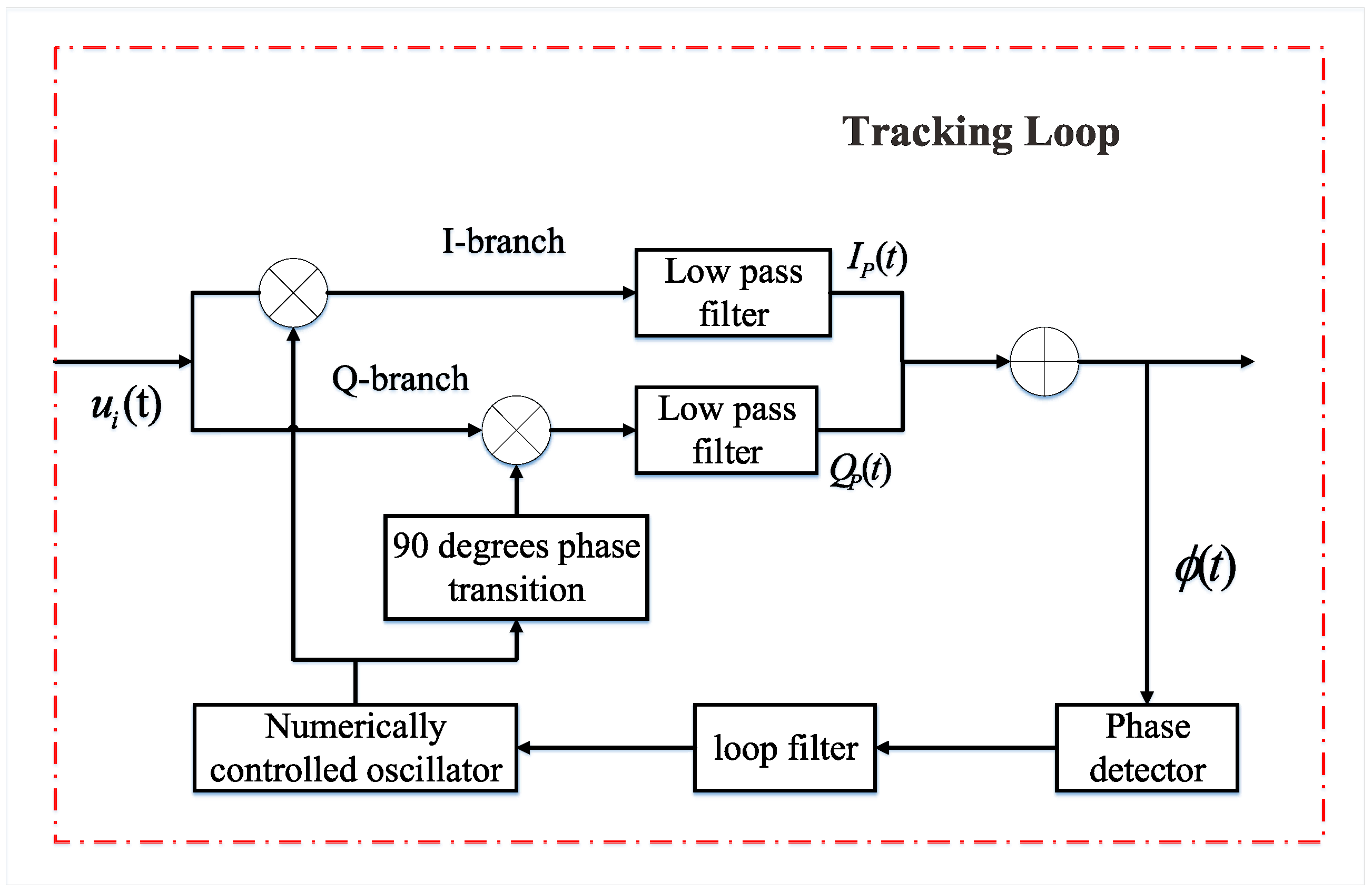
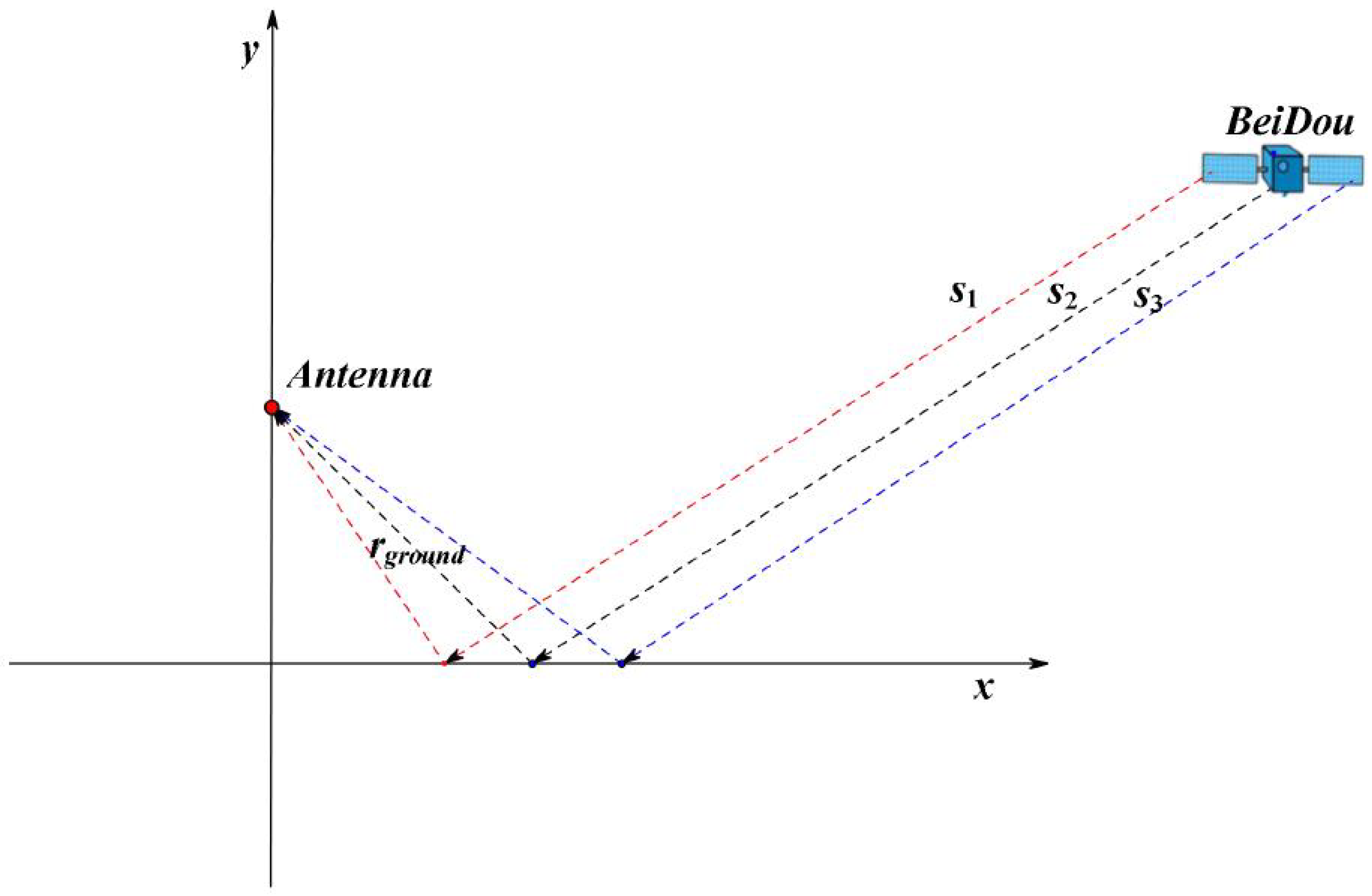
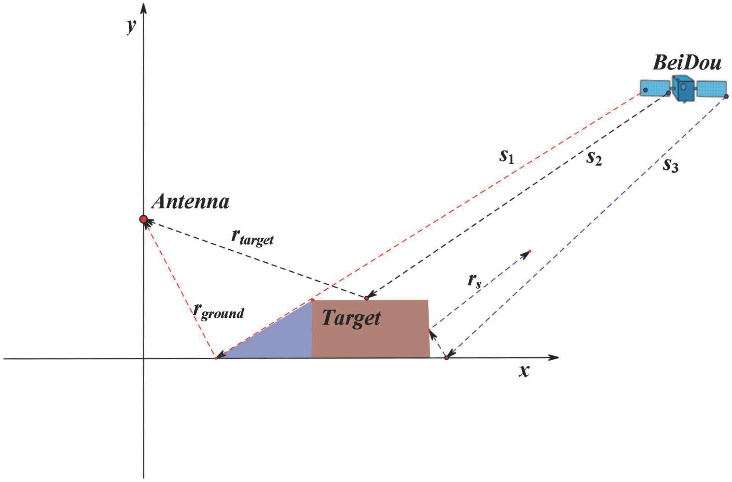
2.1. Phase Difference Analysis of Reflected Signal
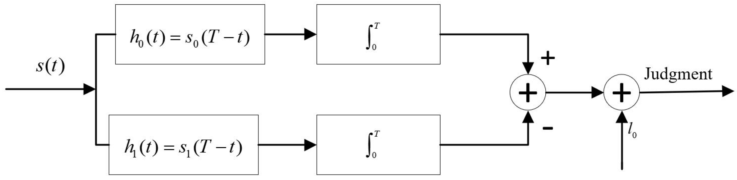
2.2. Analysis of Detection Probability
3. Experimental Campaign
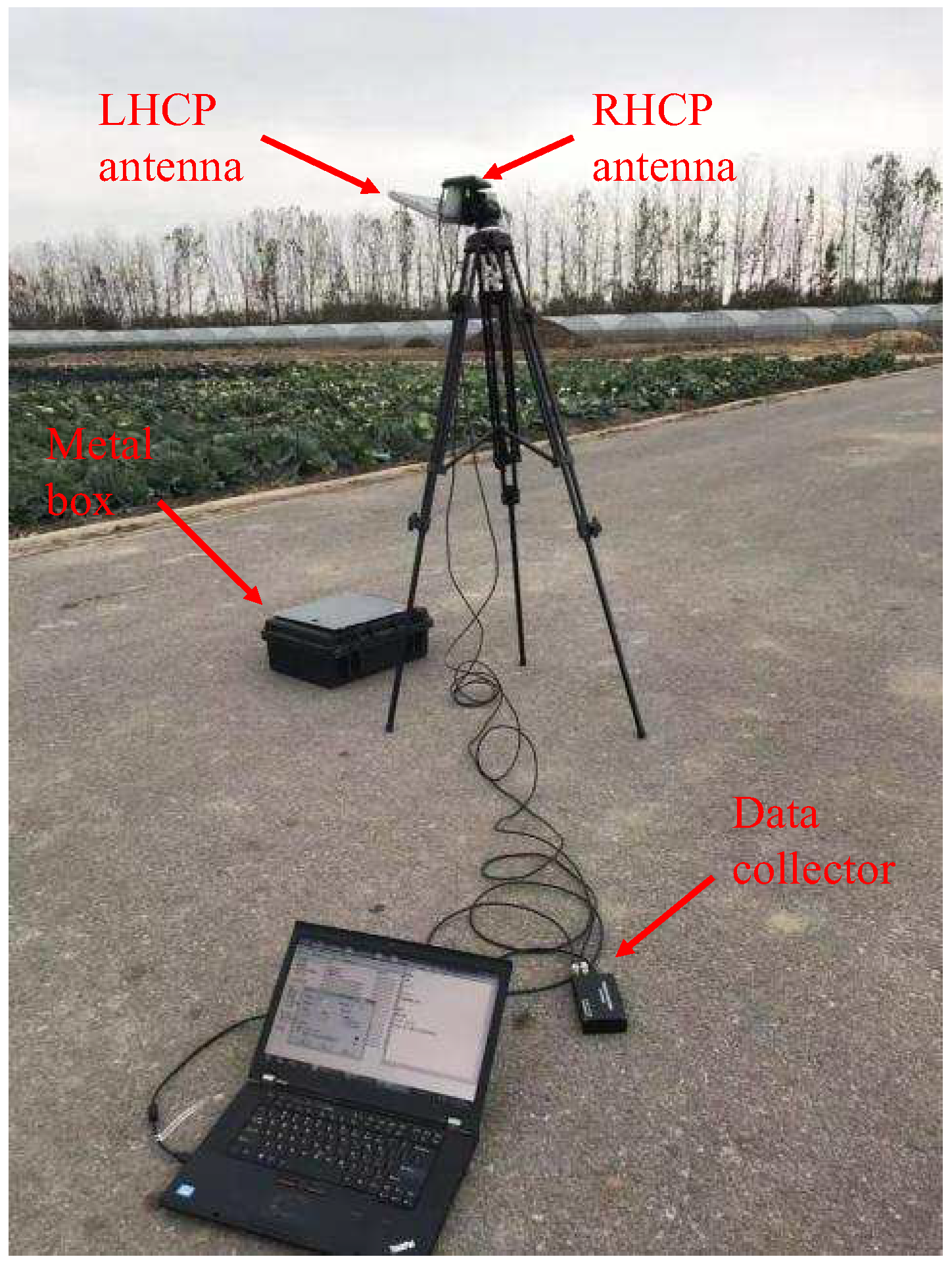
3.1. Description of the First Experiment
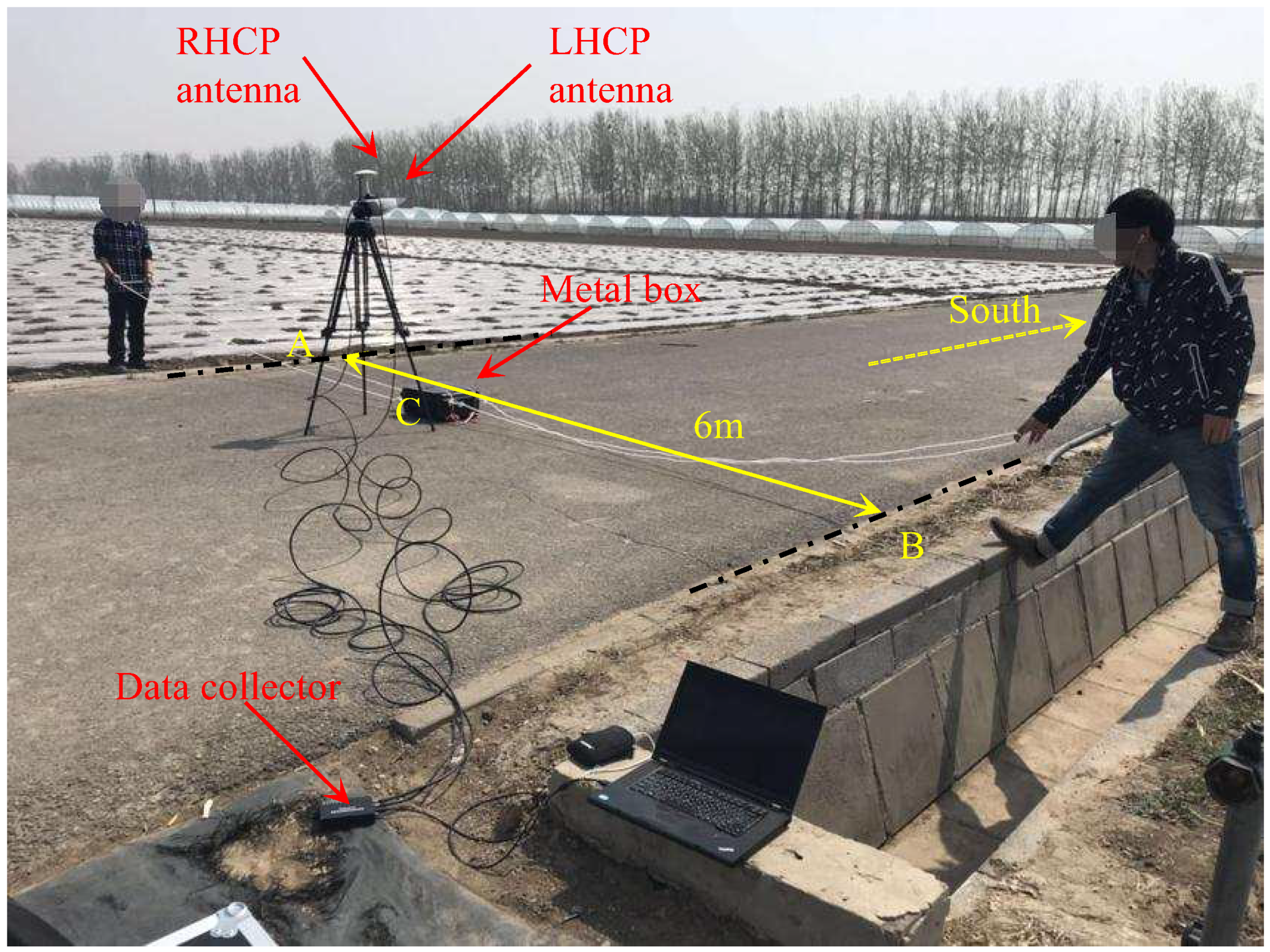
3.2. Description of the Second Experiment
4. Experimental Results
4.1. Results of the First Experiment
4.2. Results of the Second Experiment
5. Conclusions
Author Contributions
Funding
Acknowledgments
Conflicts of Interest
References
- Rodriguez-Alvarez, N.; Camps, A.; Vall-Llossera, M.; Bosch-Lluis, X.; Monerris, A.; Ramos-Perez, I.; Valencia, E.; Marchan-Hernandez, J.F.; Martinez-Fernandez, J.; Baroncini-Turricchia, G.; et al. Land Geophysical Parameters Retrieval Using the Interference Pattern GNSS-R Technique. IEEE Trans. Geosci. Remote Sens. 2010, 49, 71–84. [Google Scholar] [CrossRef]
- Ruf, C.S.; Gleason, S.; Mckague, D.S. Assessment of CYGNSS Wind Speed Retrieval Uncertainty. IEEE J. Sel. Top. Appl. Earth Obs. Remote Sens. 2018, 99, 1–11. [Google Scholar] [CrossRef]
- Gleason, S. Towards sea ice remote sensing with space detected GPS signals: Demonstration of technical feasibility and initial consis- tency check using low resolution sea ice information. Remote Sens. 2010, 2, 2017–2039. [Google Scholar] [CrossRef]
- Li, W.; Cardellach, E.; Fabra, F.; Rius, A.; Martin-Neira, M. First spaceborne phase altimetry over sea ice using TechDemoSat-1 GNSS-R signals. Geophys. Res. Lett. 2017, 44, 8369–8376. [Google Scholar] [CrossRef]
- Li, W.; Rius, A.; Fabra, F.; Cardellach, E.; Ribo, S.; Martin-Neira, M. Revisiting the GNSS-R Waveform Statistics and Its Impact on Altimetric Retrievals. IEEE Trans. Geosci. Remote Sens. 2018, 56, 2854–2871. [Google Scholar] [CrossRef]
- Cardellach, E.; Rius, A.; Martin-Neira, M.; Fabra, F.; Nogues-Correig, O.; Ribo, S.; Kainulainen, J.; Camps, A.; D’Addio, S. Consolidating the Precision of Interferometric GNSS-R Ocean Altimetry Using Airborne Experimental Data. IEEE Trans. Geosci. Remote Sens. 2014, 52, 4992–5004. [Google Scholar] [CrossRef]
- Chen, L.; Huang, W. An Algorithm for Sea-Surface Wind Field Retrieval From GNSS-R Delay-Doppler Map. Geophys. Res. Lett. 2014, 11, 2110–2114. [Google Scholar] [CrossRef]
- Valencia, E.; Zavorotny, V.U.; Akos, D.M.; Camps, A. Using DDM Asymmetry Metrics for Wind Direction Retrieval From GPS Ocean-Scattered Signals in Airborne Experiments. IEEE Trans. Geosci. Remote Sens. 2014, 52, 3924–3936. [Google Scholar] [CrossRef]
- Zavorotny, V.; Gasiewski, A.; Zamora, R.; McIntyre, E.; Leuski, V.; Irisov, V. Stationary L-band radiometry for seasonal measurements of soil moisture. IEEE Int. Symp. Geosci. Remote Sens. 2006, 13, 2028–2031. [Google Scholar]
- Camps, A.; Park, H.; Pablos, M.; Giuseppe, F.; Gommenginger, C.P.; Liu, P.; Judge, J. Sensitivity of GNSS-R Spaceborne Observations to Soil Moisture and Vegetation. IEEE J. Sel. Top. Appl. Earth Obs. Remote Sens. 2016, 9, 4730–4742. [Google Scholar] [CrossRef]
- Chen, L.; Huang, W.; Gleason, S. Dual Antenna Space-Based GNSS-R Ocean Surface Mapping: Oil Slick and Tropical Cyclone Sensing. IEEE J. Sel. Top. Appl. Earth Obs. Remote Sens. 2015, 8, 425–435. [Google Scholar]
- Cardellach, E.; Fabra, F.; Rius, A.; Pettinato, S.; D’Addio, S. Characterization of dry-snow sub-structure using GNSS reflected signals. Remote Sens. Environ. 2012, 124, 122–134. [Google Scholar] [CrossRef]
- Carreno-Luengo, H.; Camps, A. First Dual-Band Multiconstellation GNSS-R Scatterometry Experiment Over Boreal Forests From a Stratospheric Balloon. IEEE J. Sel. Top. Appl. Earth Obs. Remote Sens. 2016, 10, 4743–4751. [Google Scholar] [CrossRef]
- Carreno-Luengo, H.; Lowe, S.; Zuffada, C.; Esterhuizen, S.; Ovesigharan, S. GNSS-R from the SMAP and CyGNSS missions: Application to polarimetric scatterometry and ocean altimetry. In Proceedings of the 2017 IEEE International Geoscience and Remote Sensing Symposium (IGARSS), Fort Worth, TX, USA, 23–28 July 2017. [Google Scholar]
- Carreno-Luengo, H.; Lowe, S.; Zuffada, C.; Esterhuizen, S.; Ovesigharan, S. Spaceborne GNSS-R from the SMAP mission: First assessment of polarimetric scatterometry over land and cryosphere. Remote Sens. 2017, 9, 362. [Google Scholar] [CrossRef]
- Carreno-Luengo, H.; Camps, A.; Querol, J.; Forte, G. First Results of a GNSS-R Experiment from a Stratospheric Balloon Over Boreal Forests. IEEE Trans. Geosci. Remote Sens. 2016, 54, 2652–2663. [Google Scholar] [CrossRef]
- Fabra, F.; Cardellach, E.; Rius, A.; Ribo, S. Phase Altimetry with Dual Polarization GNSS-R over Sea Ice. IEEE J. Sel. Top. Appl. Earth Obs. Remote Sens. 2012, 50, 2112–2121. [Google Scholar] [CrossRef]
- He, L.; Ge, M.; Wang, J.; Wichert, J.; Schuh, H. Experimental Study on the Precise Orbit Determination of the BeiDou Navigation Satellite System. Sensors 2013, 13, 2911–2928. [Google Scholar] [CrossRef] [PubMed]
- Wang, G.; De Jong, K.; Zhao, Q.; Hu, Z.; Guo, J. Multipath analysis of code measurements for BeiDou geostationary satellites. GPS Solut. 2015, 19, 129–139. [Google Scholar] [CrossRef]
- Zhang, Y.; Tian, L.; Meng, W.; Gu, Q.; Han, Y.; Hong, Z. Feasibility of Code-Level Altimetry Using Coastal BeiDou Reflection (BeiDou-R) Setups. IEEE J. Sel. Top. Appl. Earth Obs. Remote Sens. 2015, 8, 4130–4140. [Google Scholar] [CrossRef]
- Li, W.; Fabra, F.; Yang, D.; Rius, A.; Martin-Neria, M.; Yin, C.; Wang, Q.; Cao, Y. Initial Results of Typhoon Wind Speed Observation Using Coastal GNSS-R of BeiDou GEO Satellite. IEEE J. Sel. Top. Appl. Earth Obs. Remote Sens. 2016, 9, 4720–4729. [Google Scholar] [CrossRef]
- Li, W.; Yang, D.; Fabra, F.; Cao, Y.; Yang, W. Typhoon Wind Speed Observation Utilizing Reflected Signals from BeiDou GEO Satellites. In China Satellite Navigation Conference (CSNC) 2014 Proceedings: Volume III; Sun, J., Jiao, W., Wu, H., Lu, M., Eds.; Springer: Berlin/Heidelberg, Germany, 2014; pp. 191–200. [Google Scholar]
- Wang, F.; Zhang, B.; Yang, D.; Li, W.; Zhu, Y. Sea-State Observation Using Reflected BeiDou GEO Signals in Frequency Domain. IEEE Geosci. Remote Sens. Lett. 2016, 13, 1656–1660. [Google Scholar] [CrossRef]
- Zhang, Y.; Xie, X.; Meng, W.; Yang, S.; Gao, Q.; Wang, W. Bohai coastal sea ice detection using BeiDou GEO satellite reflected signals. J. Beijing Univ. Aeronaut. Astronaut. 2018, 44, 257–263. (In Chinese) [Google Scholar]
- Gao, H.; Yang, D.; Li, W.; Wang, Q.; Wang, F.; Yin, C. Detection of sea ice based on BeiDou-reflected signals. In Proceedings of the 2016 IEEE International Geoscience and Remote Sensing Symposium, Beijing, China, 10–15 July 2016; pp. 4872–4875. [Google Scholar]
- Yang, L.; Wu, Q.; Zhang, B.; Hong, X.; Zou, W. SVRM-assisted soil moisture retrieval method using reflected signal from BeiDou GEO satellites. J. Beijing Univ. Aeronaut. Astronaut. 2016, 42, 1134–1141. (In Chinese) [Google Scholar]
- Yan, S.H.; Zhao, F.; Chen, N.C.; Gong, J.Y. Soil moisture estimation based on BeiDou Bl interference signal analysis. Sci. China Earth Sci. 2016, 59, 2427–2440. [Google Scholar] [CrossRef]
- Gao, C.; Yang, D.; Hong, X.; Xu, Y.; Wang, B.; Zhu, Y. Experimental Results About Traffic Flow Detection by Using GPS Reflected Signals. IEEE J. Sel. Top. Appl. Earth Obs. Remote Sens. 2018, 11, 5076–5087. [Google Scholar] [CrossRef]
- Tawk, Y.; Tome, P.; Botteron, C.; Stebler, Y.; Farine, P.A. Implementation and performance of a GPS/INS tightly coupled assisted PLL architecture using MEMS inertial sensors. Sensors 2014, 14, 3768–3796. [Google Scholar] [CrossRef]
- Stevanovic, S.; Pervan, B. A GPS Phase-Locked Loop Performance Metric Based on the Phase Discriminator Output. Sensors 2018, 18, 296. [Google Scholar] [CrossRef]
- Hofmann-Wellenhof, B.; Lichtenegger, H.; Collins, J. Global Positioning System: Theory and Practice; Springer: Wien, Austria, 2001. [Google Scholar]
- Zhao, Q.; Wang, C.; Guo, J.; Liu, X. Assessment of the Contribution of BeiDou GEO, IGSO, and MEO Satellites to PPP in Asia-Pacific Region. Sensors 2015, 15, 29970–29983. [Google Scholar] [CrossRef] [PubMed]
- Li, W.; Yang, D.; D’Addio, S.; Martin-Neira, M. Partial Interferometric Processing of Reflected GNSS Signals for Ocean Altimetry. IEEE Geosci. Remote Sens. Lett. 2014, 11, 1509–1513. [Google Scholar]
- Motte, E.; Zribi, M. Optimizing Waveform Maximum Determination for Specular Point Tracking in Airborne GNSS-R. Sensors 2017, 17, 1880. [Google Scholar] [CrossRef] [PubMed]
- Southwell, B.J.; Dempster, A.G. A New Approach to Determine the Specular Point of Forward Reflected GNSS Signals. IEEE J. Sel. Top. Appl. Earth Obs. Remote Sens. 2018, 111, 639–646. [Google Scholar] [CrossRef]
- Garrison, J.L. A Statistical Model and Simulator for Ocean-Reflected GNSS Signals. IEEE Trans. Geosci. Remote Sens. 2016, 54, 6007–6019. [Google Scholar] [CrossRef]
- Chew, C.C.; Small, E.E.; Larson, K.M.; Zavorotny, V.U. Effects of Near-Surface Soil Moisture on GPS SNR Data: Development of a Retrieval Algorithm for Soil Moisture. IEEE Trans. Geosci. Remote Sens. 2013, 52, 537–543. [Google Scholar] [CrossRef]
- Tabibi, S.; Nievinski, F.G.; Dam, T.V.; Monico, J.F.G. Assessment of modernized GPS L5 SNR for ground-based multipath reflectometry applications. Adv. Space Res. 2015, 55, 1104–1116. [Google Scholar] [CrossRef]


| Length | Width | Height |
|---|---|---|
| 40 cm | 33 cm | 20 cm |
| Number of the Target Passing through the Antenna | Time (s) |
|---|---|
| 1 | 15.05 |
| 2 | 28.08 |
| 3 | 40.09 |
| 4 | 53.05 |
| 5 | 64.05 |
| 6 | 77.04 |
| 7 | 89.02 |
| 8 | 107.07 |
| 9 | 113.04 |
| 10 | 125.09 |
| 11 | 138.02 |
| 12 | 150.00 |
| 13 | 162.00 |
| 14 | 174.07 |
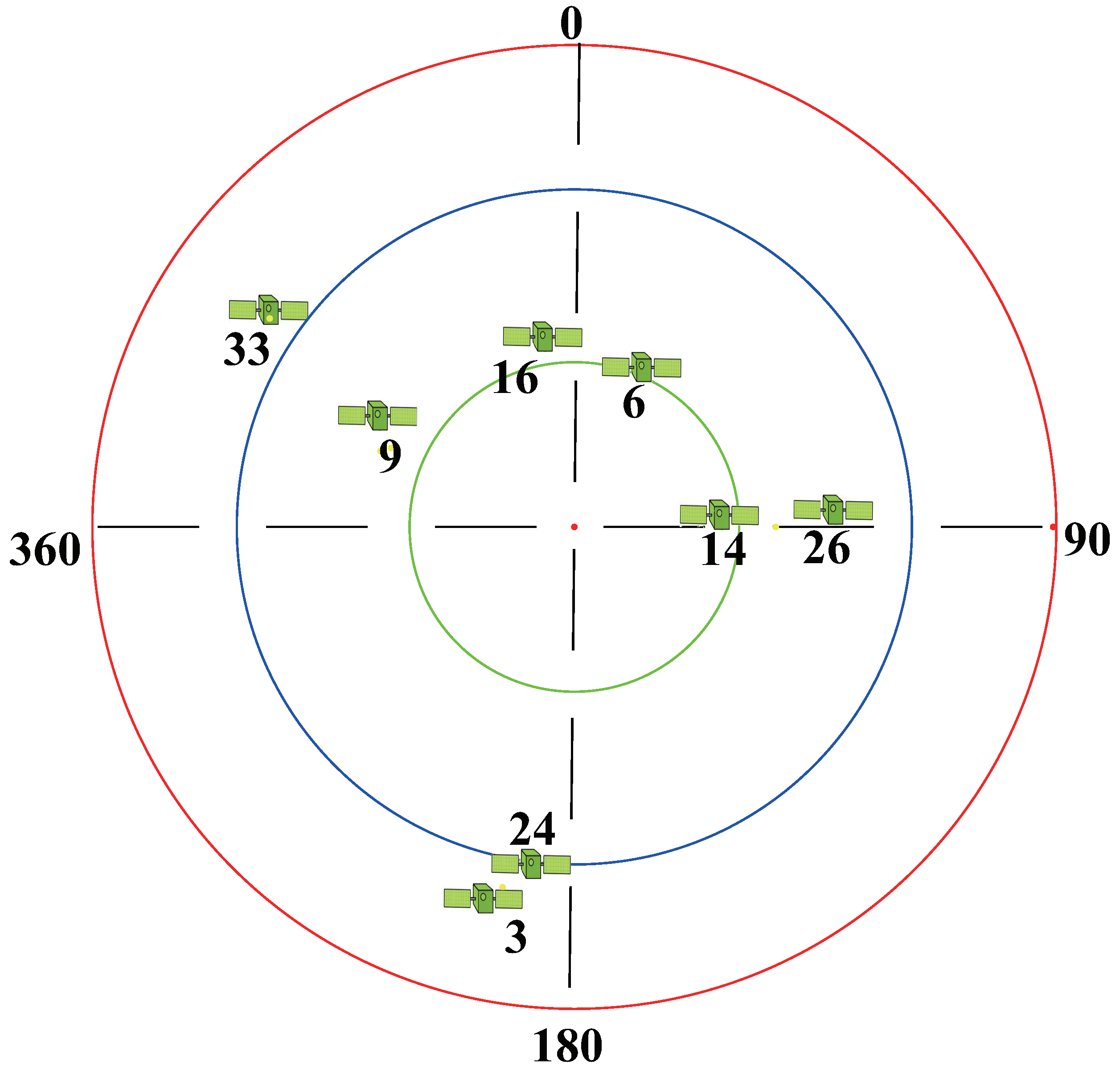
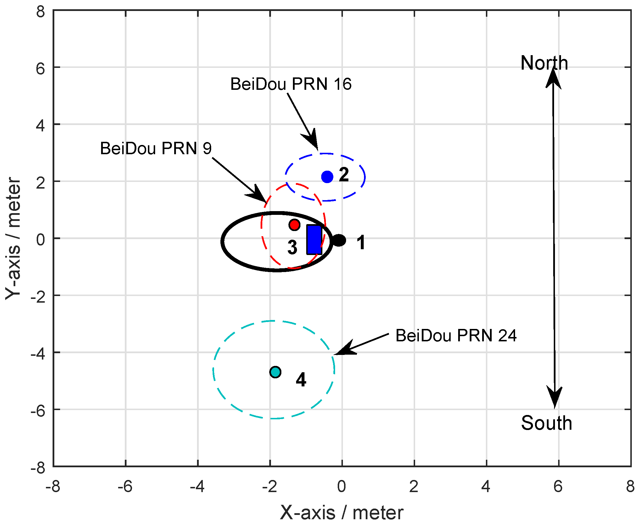
| Satellite Orbit | PRN | Elevation Angle | Azimuth |
|---|---|---|---|
| IGSO | 9 | ||
| MEO | 16 | ||
| MEO | 24 |
| Satellite Orbit | PRN | Elevation Angle | Azimuth |
|---|---|---|---|
| GEO | 2 | ||
| GEO | 3 | ||
| IGSO | 8 | ||
| MEO | 23 | ||
| MEO | 27 |
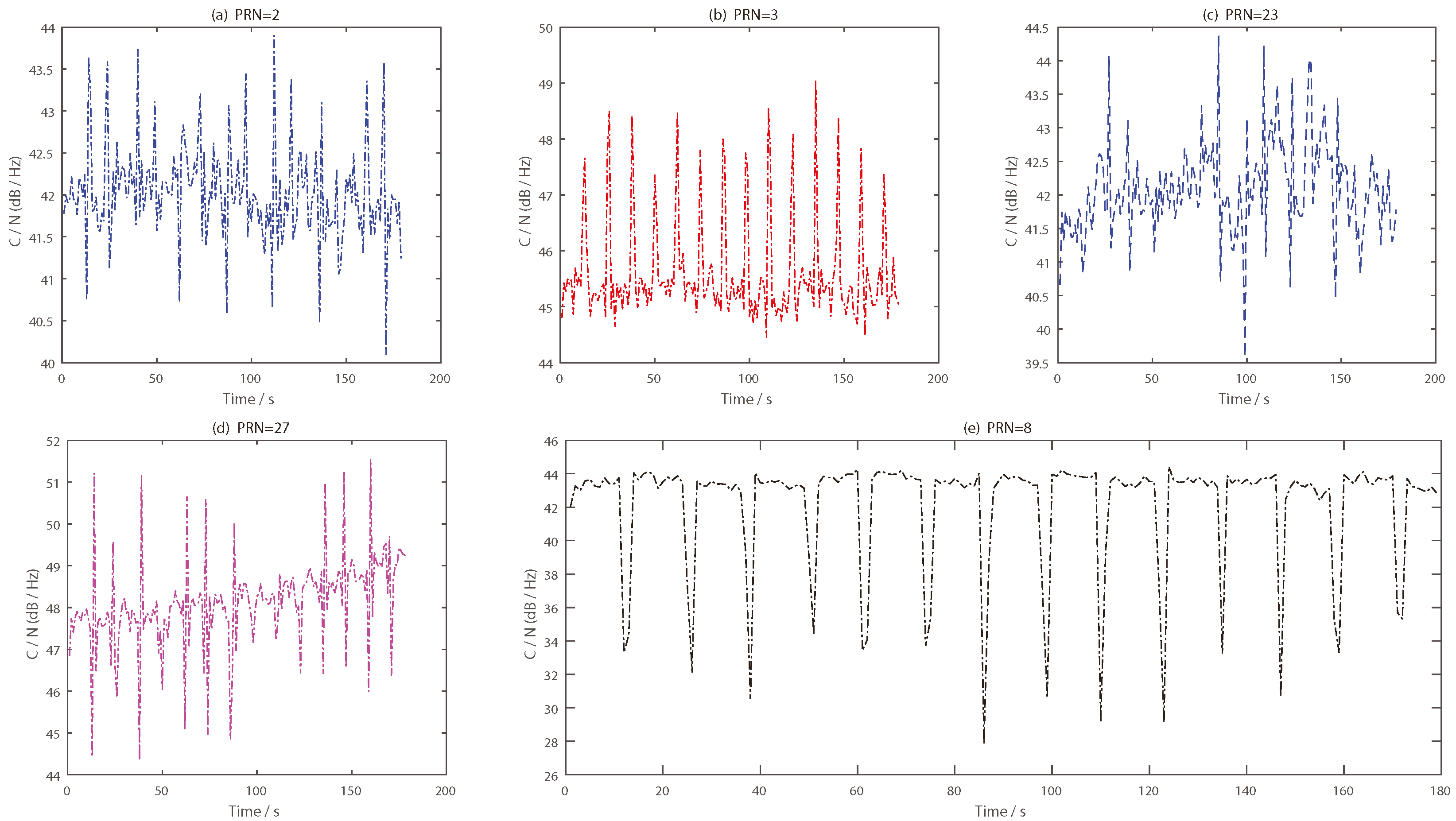
| Number | Time (s) | PRN2 (s) | PRN3 (s) | PRN8 (s) | PRN23 (s) | PRN28 (s) |
|---|---|---|---|---|---|---|
| 1 | 15.05 | 13 | 13 | 13 | 11 | 13 |
| 2 | 28.08 | 24 | 26 | 26 | 26 | 25 |
| 3 | 40.09 | 38 | 38 | 38 | 36 | 38 |
| 4 | 53.05 | 49 | 50 | 51 | 50 | 50 |
| 5 | 64.05 | 62 | 62 | 62 | 60 | 62 |
| 6 | 77.04 | 73 | 74 | 75 | 75 | 74 |
| 7 | 89.02 | 87 | 86 | 87 | 85 | 86 |
| 8 | 107.07 | 97 | 98 | 99 | 99 | 98 |
| 9 | 113.04 | 111 | 110 | 111 | 109 | 111 |
| 10 | 125.09 | 121 | 123 | 123 | 123 | 122 |
| 11 | 138.02 | 135 | 135 | 135 | 133 | 135 |
| 12 | 150.00 | 145 | 147 | 147 | 147 | 146 |
| 13 | 162.00 | 159 | 159 | 159 | 157 | 159 |
| 14 | 174.07 | 170 | 171 | 172 | 172 | 171 |
| Detection parameter | Null | A | A/C | A/B/C | A | A/B |
© 2019 by the authors. Licensee MDPI, Basel, Switzerland. This article is an open access article distributed under the terms and conditions of the Creative Commons Attribution (CC BY) license (http://creativecommons.org/licenses/by/4.0/).
Share and Cite
Gao, C.; Yang, D.; Hong, X.; Wang, B.; Zhang, B. Performance Analysis of Ground Target Detection Utilizing Beidou Satellite Reflected Signals. Sensors 2019, 19, 2163. https://doi.org/10.3390/s19092163
Gao C, Yang D, Hong X, Wang B, Zhang B. Performance Analysis of Ground Target Detection Utilizing Beidou Satellite Reflected Signals. Sensors. 2019; 19(9):2163. https://doi.org/10.3390/s19092163
Chicago/Turabian StyleGao, Chaoqun, Dongkai Yang, Xuebao Hong, Bo Wang, and Bo Zhang. 2019. "Performance Analysis of Ground Target Detection Utilizing Beidou Satellite Reflected Signals" Sensors 19, no. 9: 2163. https://doi.org/10.3390/s19092163
APA StyleGao, C., Yang, D., Hong, X., Wang, B., & Zhang, B. (2019). Performance Analysis of Ground Target Detection Utilizing Beidou Satellite Reflected Signals. Sensors, 19(9), 2163. https://doi.org/10.3390/s19092163