Research on the Earth Pressure and Internal Force of a High-Fill Open-Cut Tunnel Using a Bilayer Lining Design: A Field Test Using an FBG Automatic Data Acquisition System

Abstract
1. Introduction
- (1)
- The height of backfill layer can reach up to 30–40 m, which is almost five times larger than a common one;
- (2)
- In order to bear such high earth pressure, the thickness of the tunnel lining can reach up to 2 m or more, which is 4–5 times thicker than those with shallow overburden. Details of existing high-fill open-cut tunnels in China are shown in Table 1.
2. Field Test Procedure
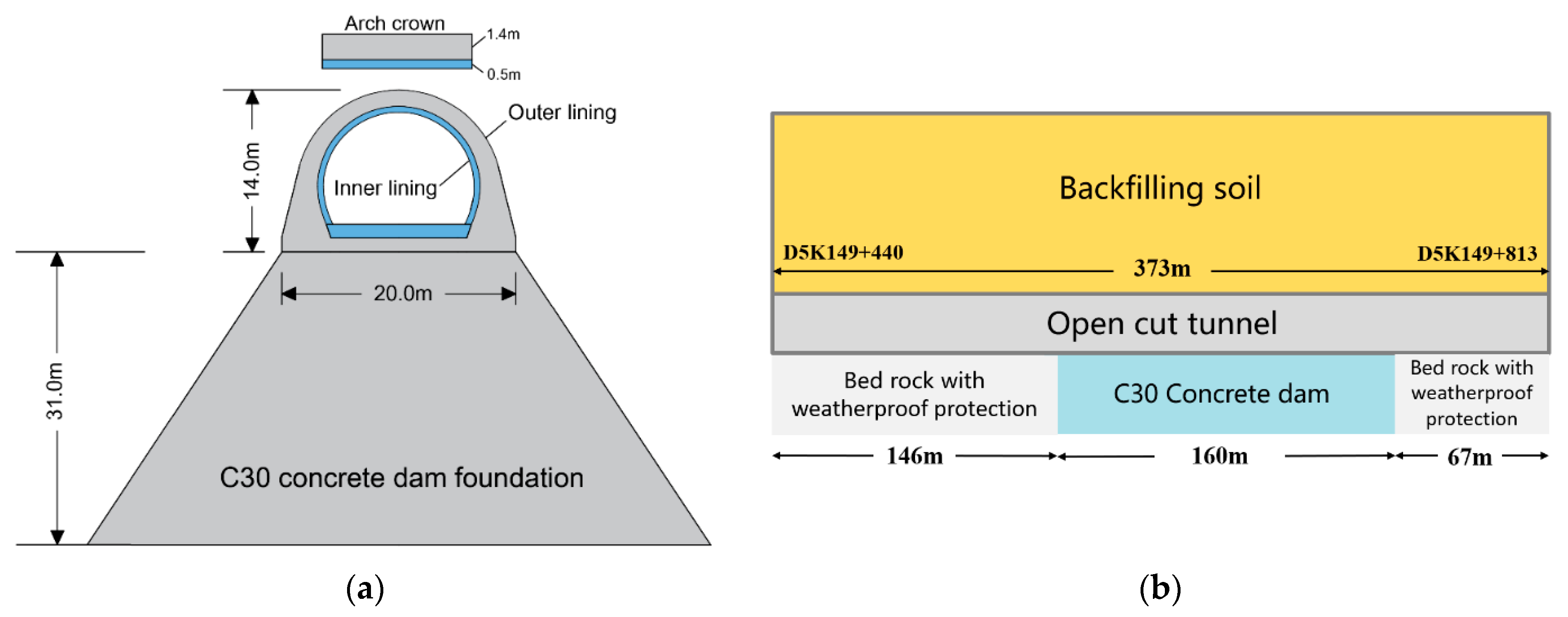
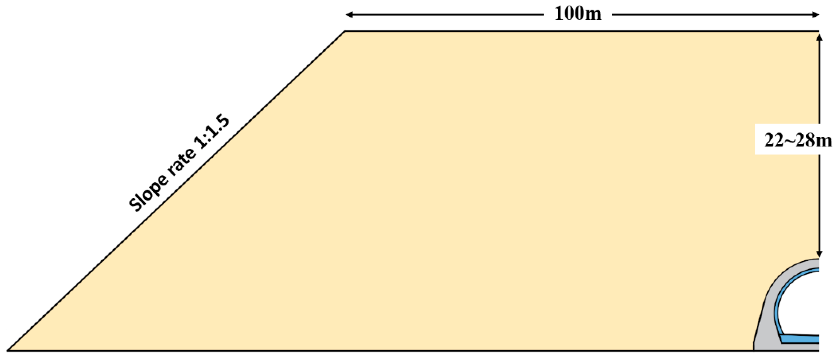
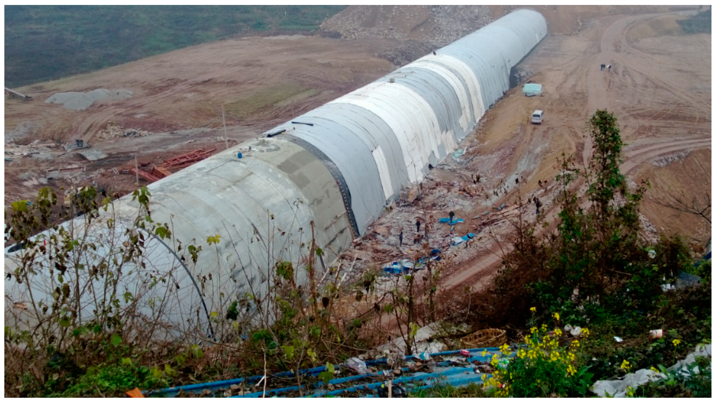
2.1. Tunnel Description
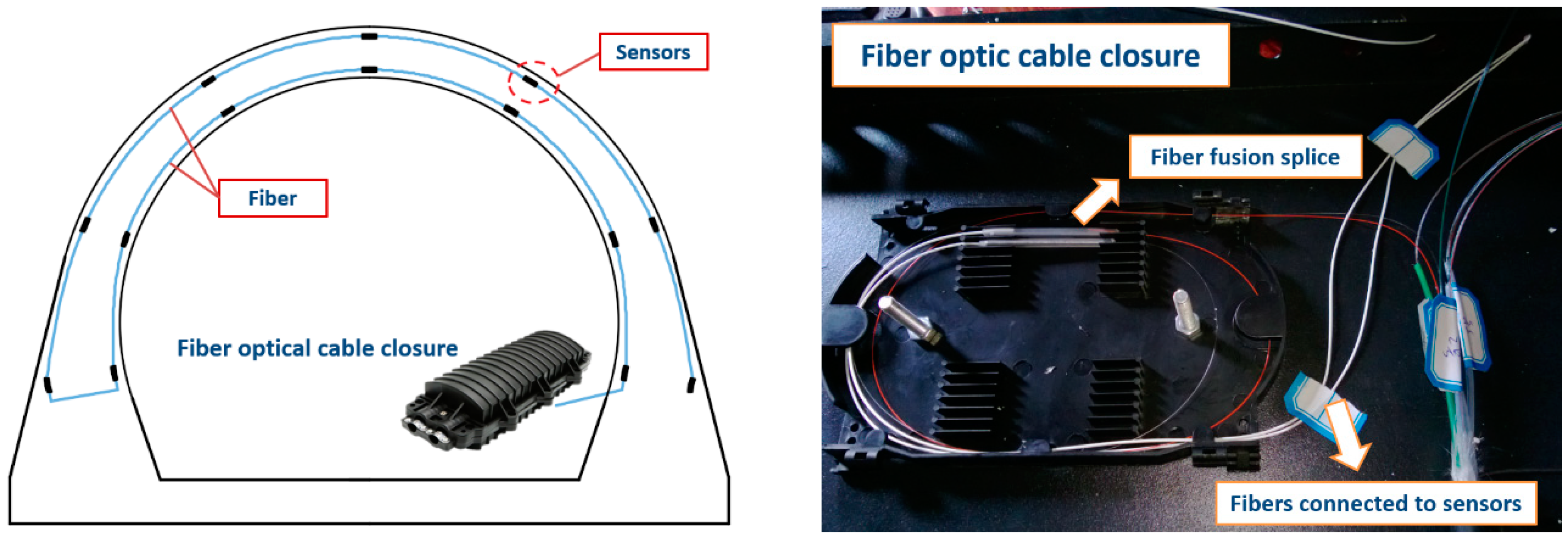
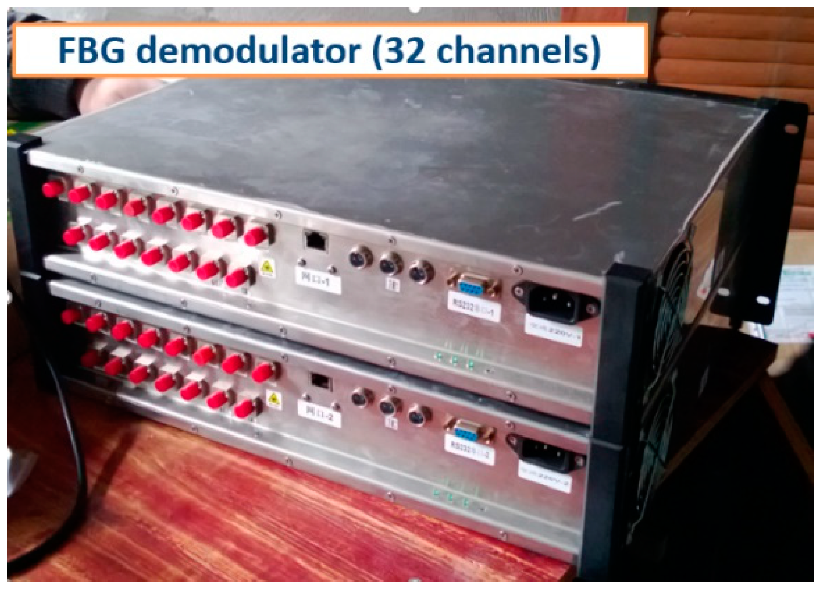
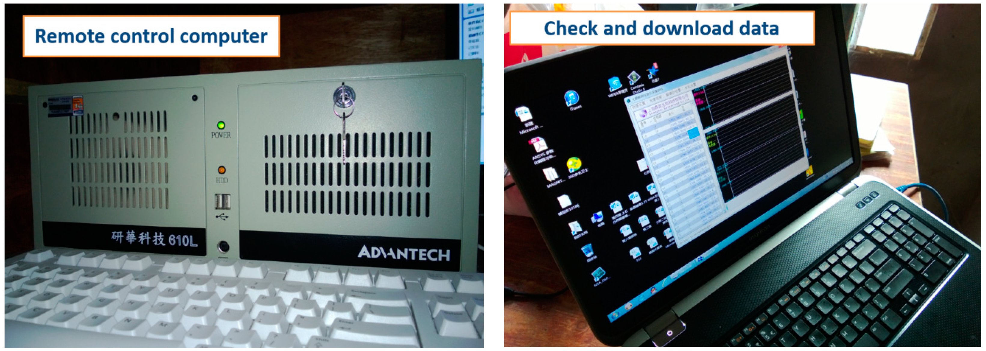
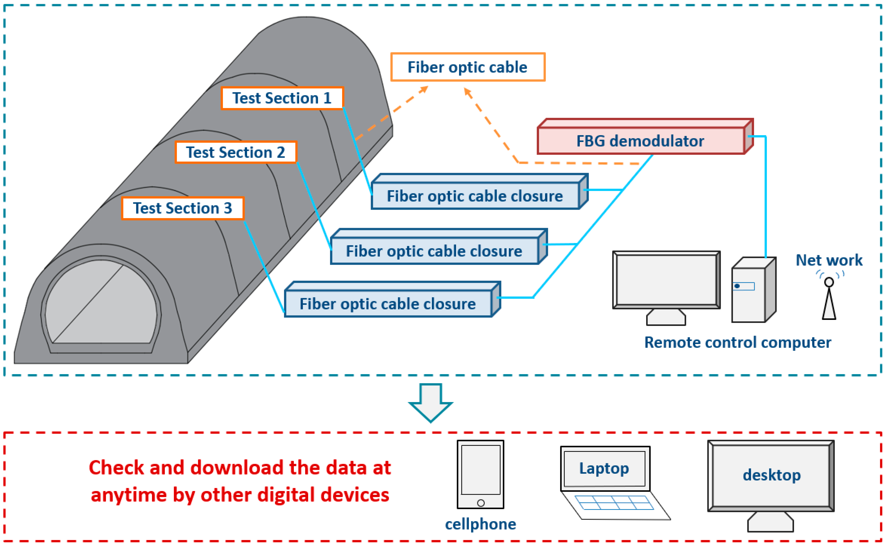
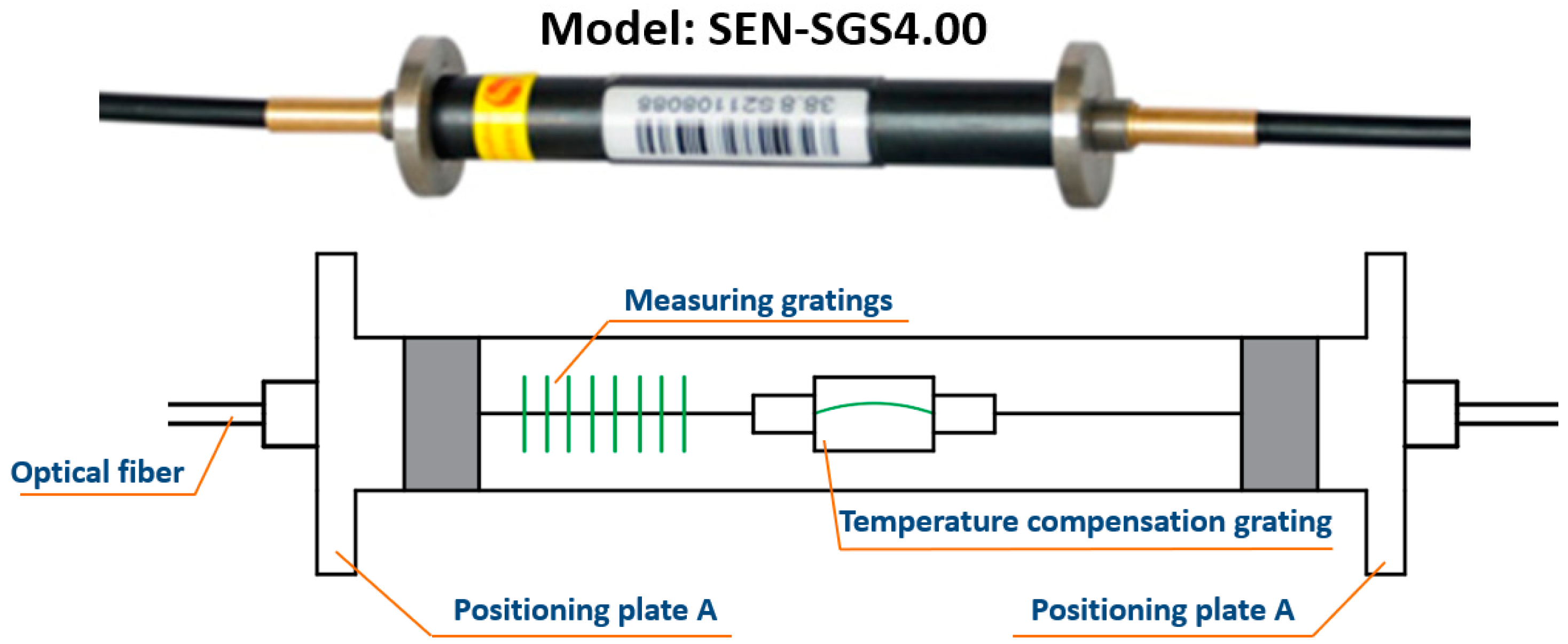
2.2. Automatic Data Acquisition System
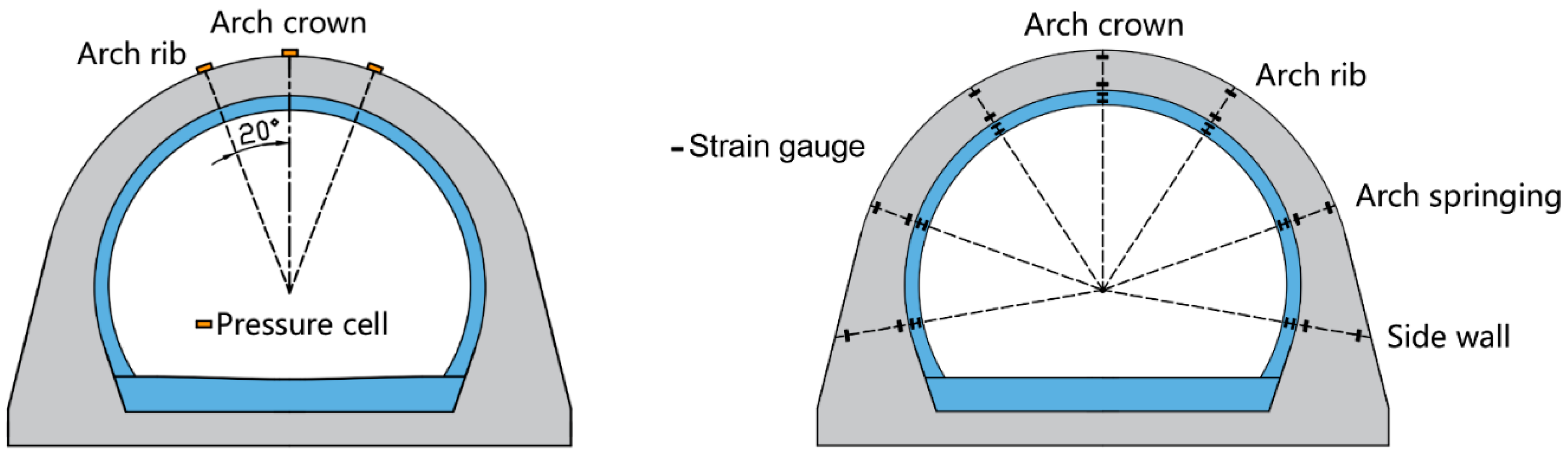
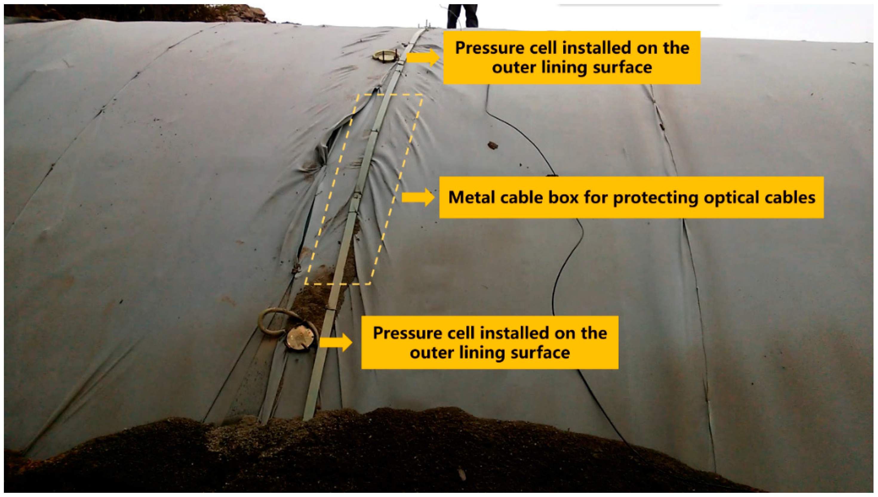
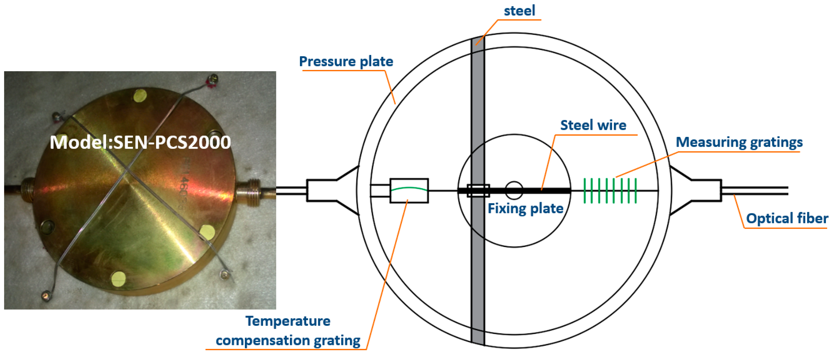
2.3. Sensor Layout and Basic Structure
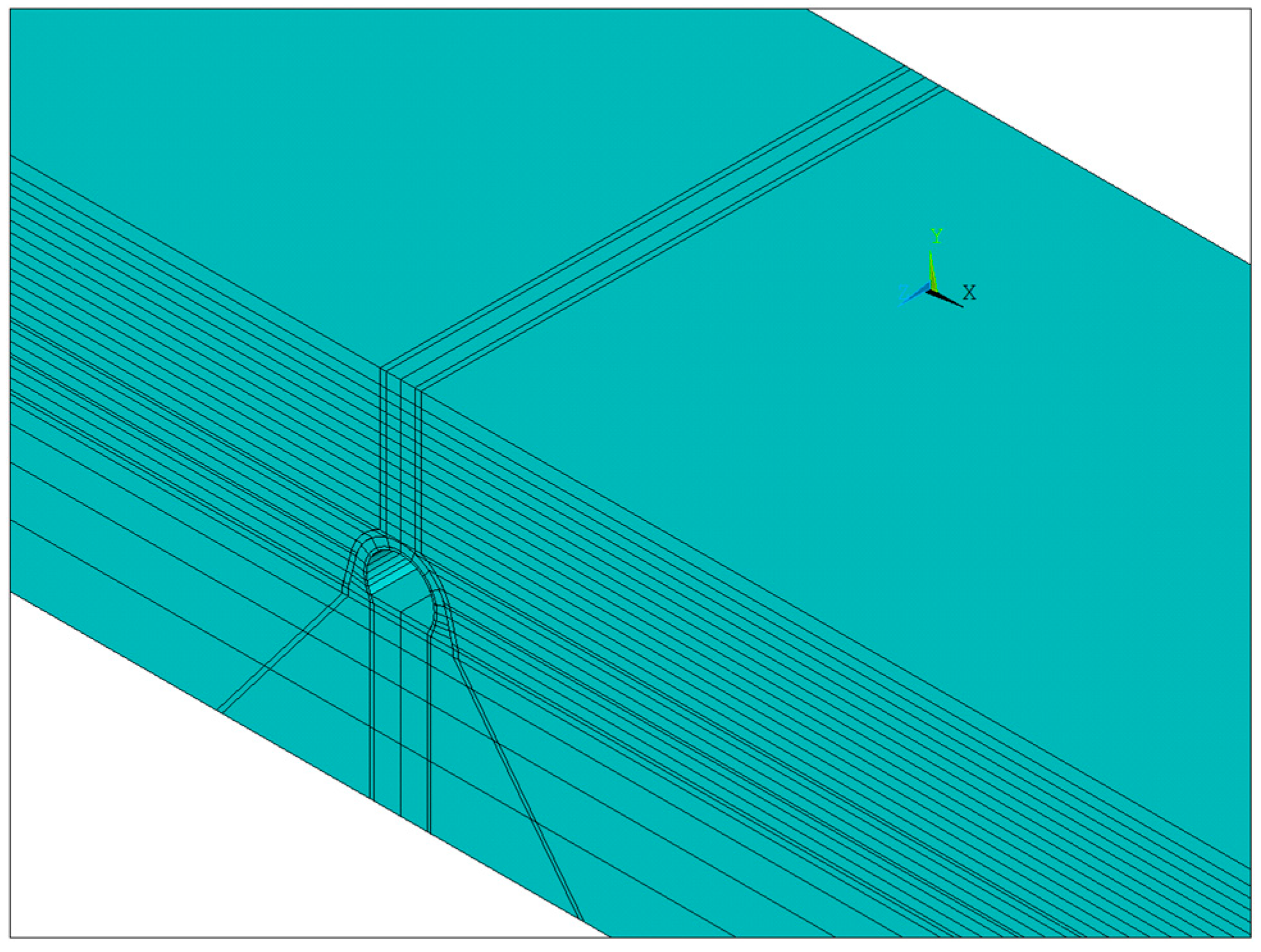
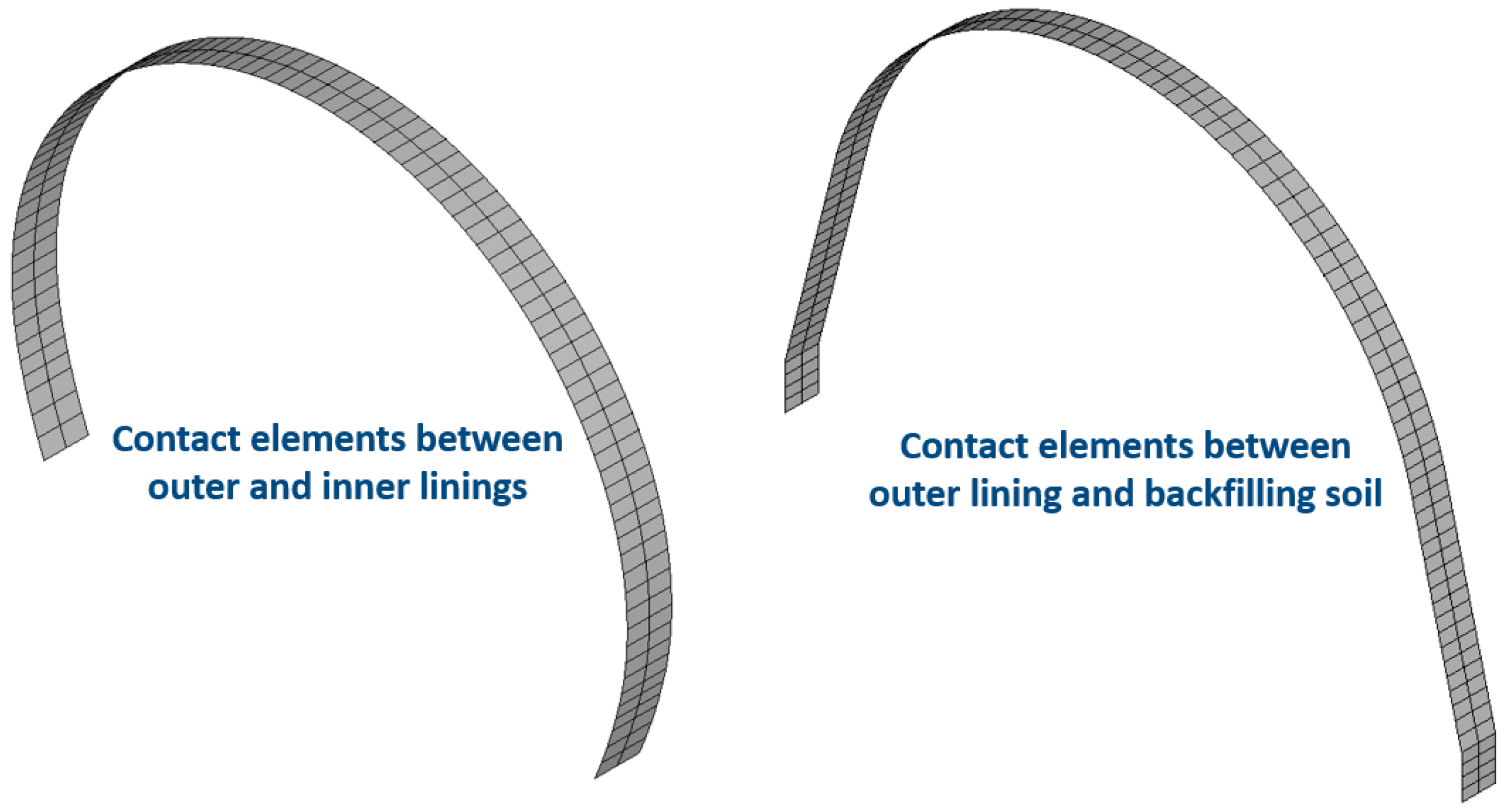
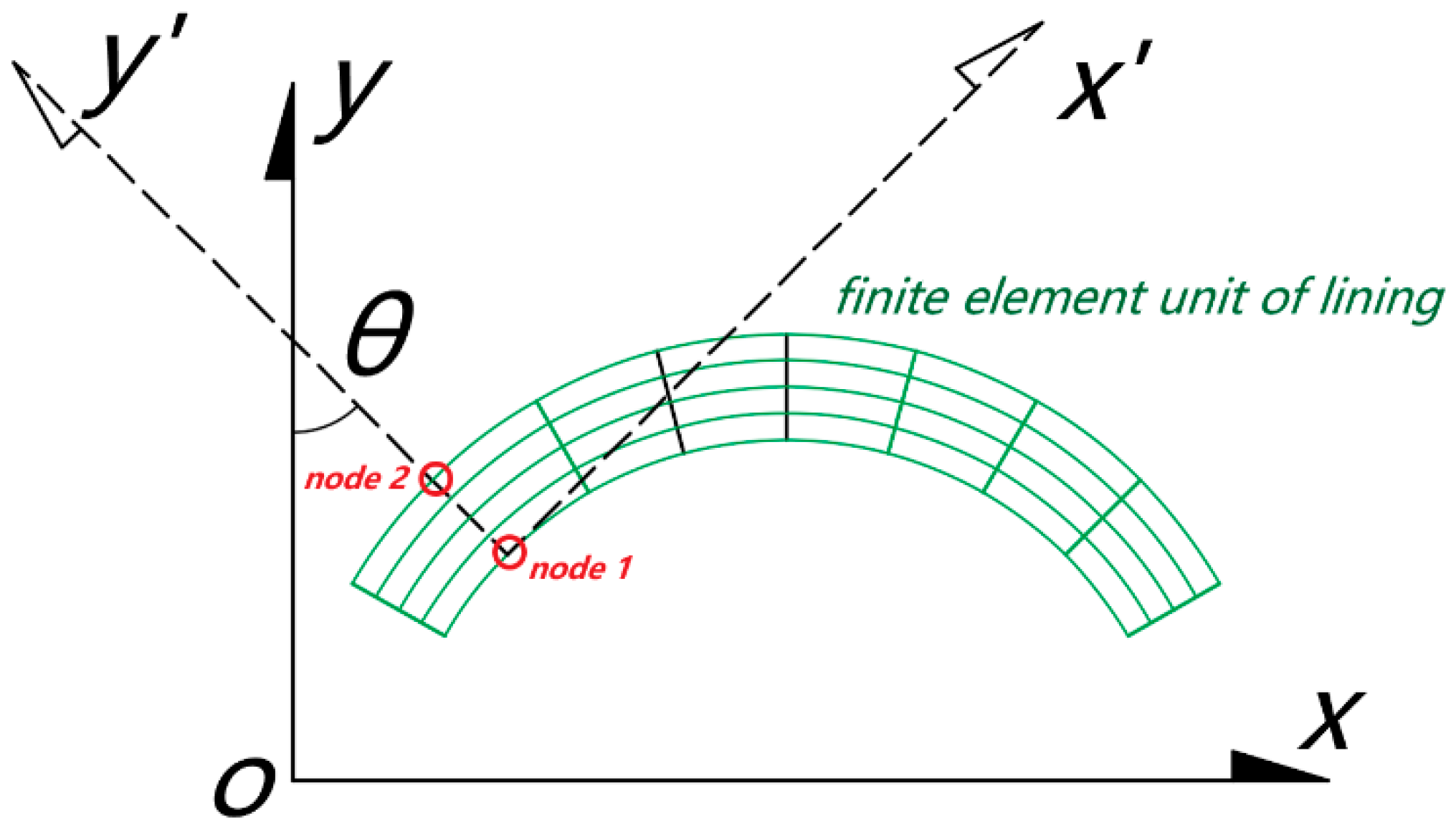
3. Numerical Model
4. Earth Pressure Test Results and Discussion
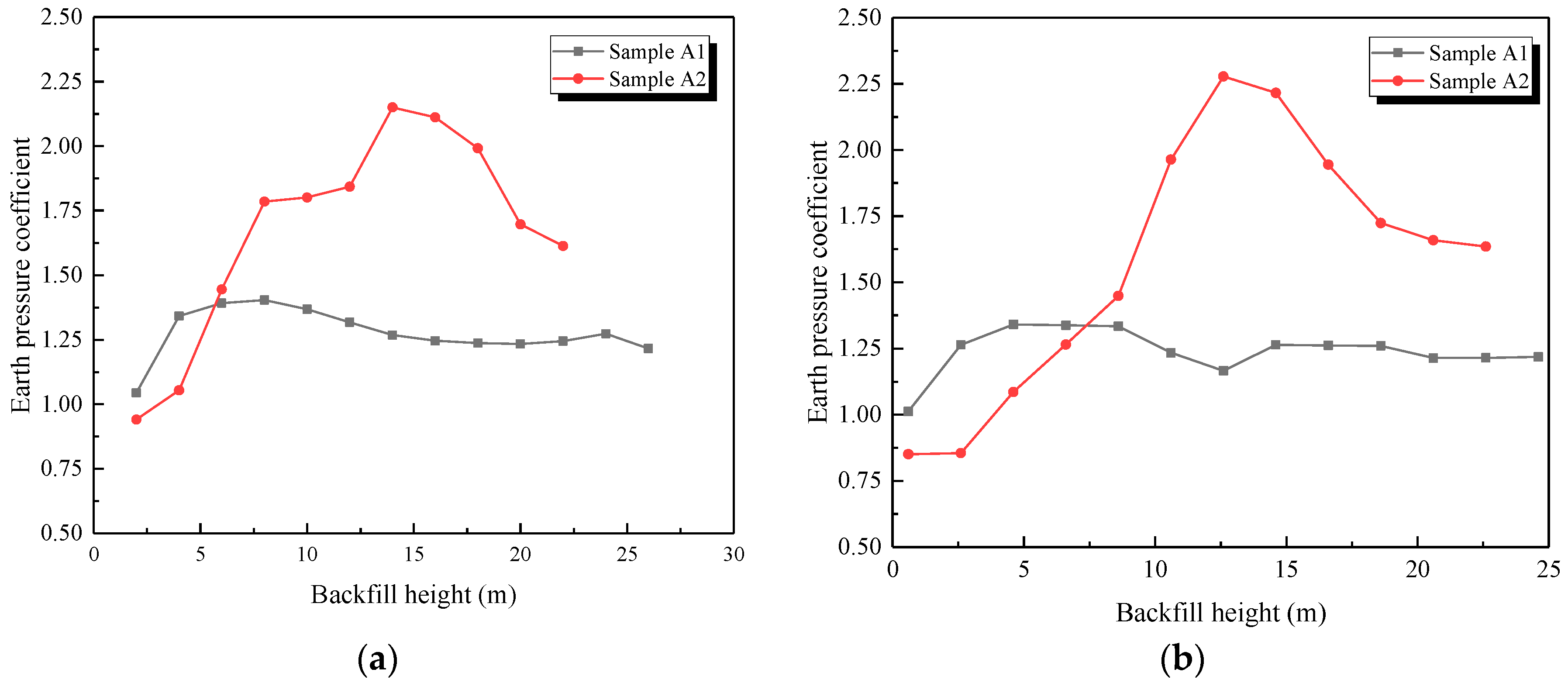
4.1. Earth Pressure Test Results
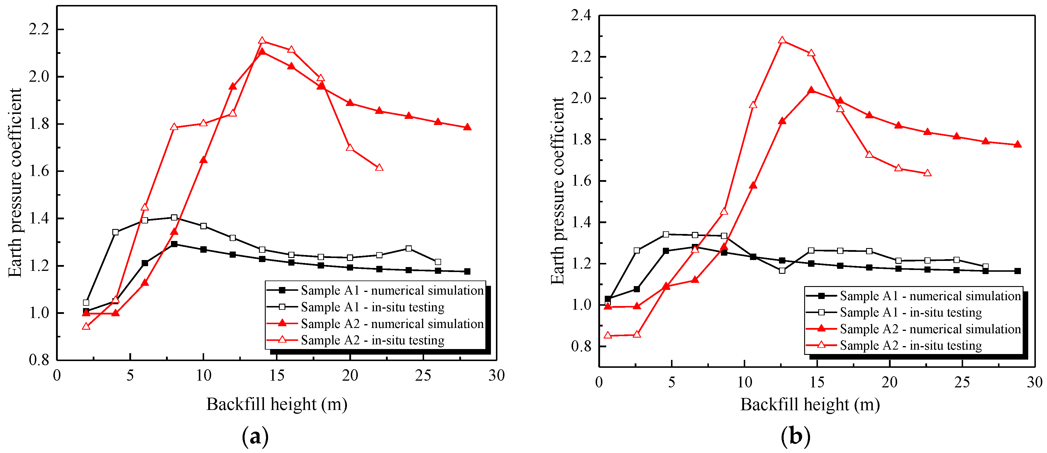
4.2. The Comparative Analysis of In Situ Testing and Numerical Simulation
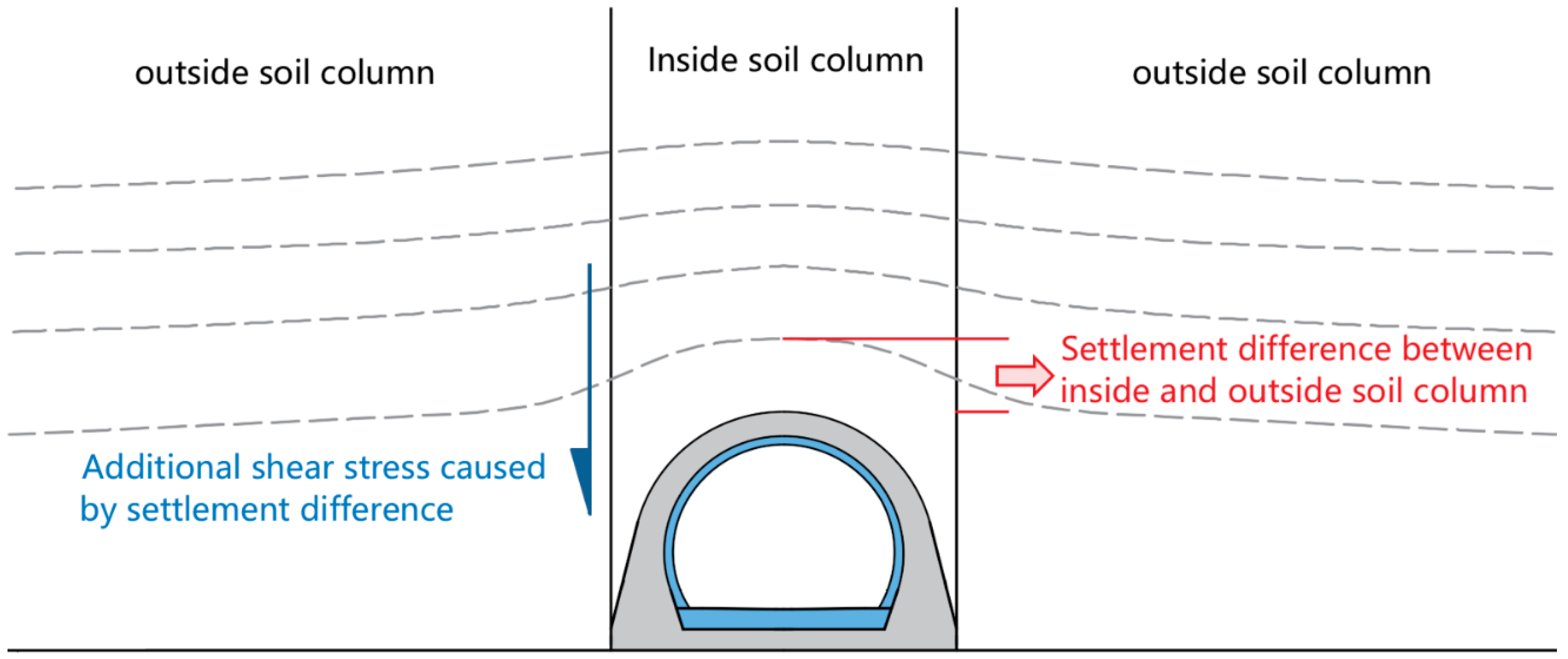
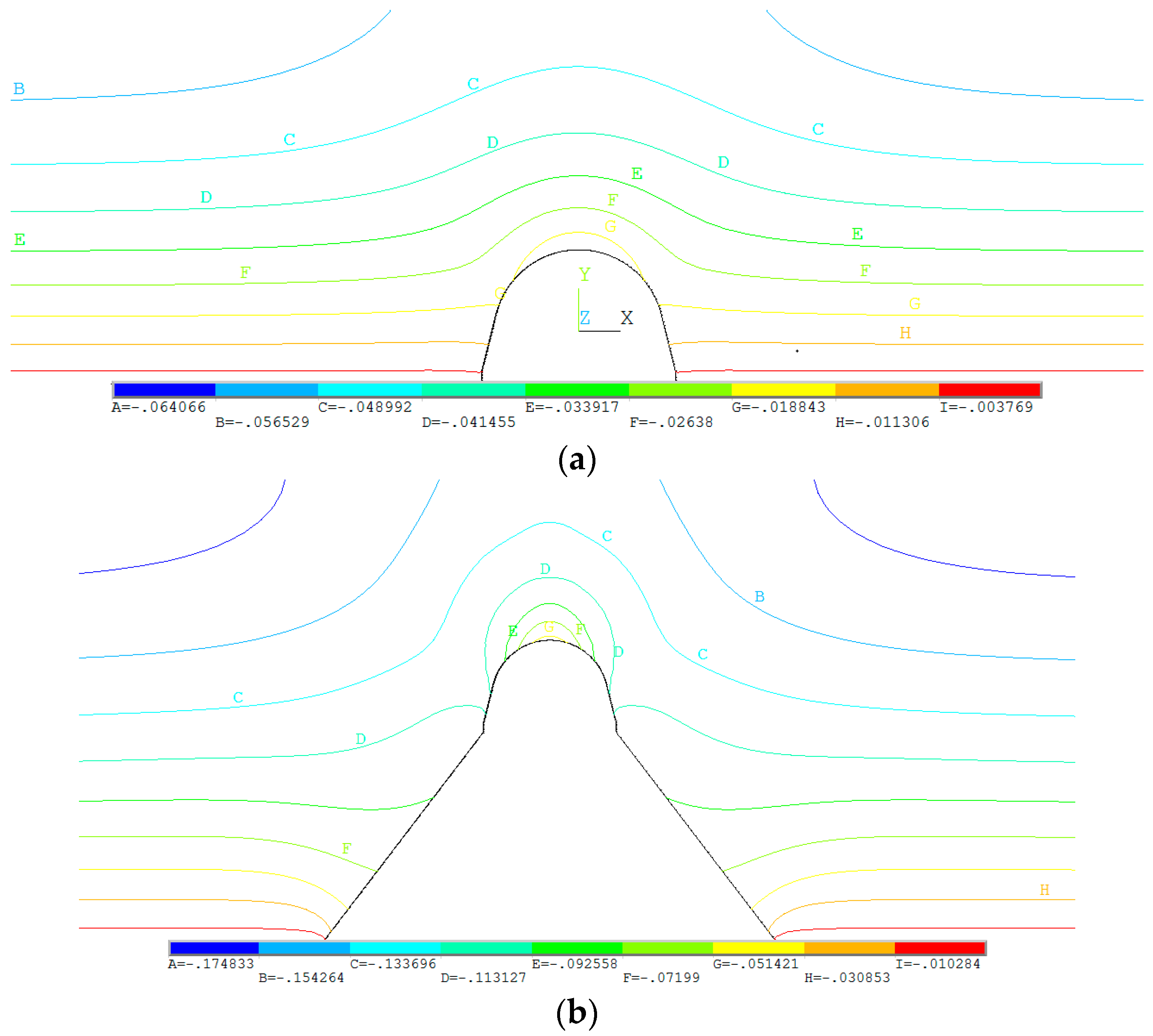
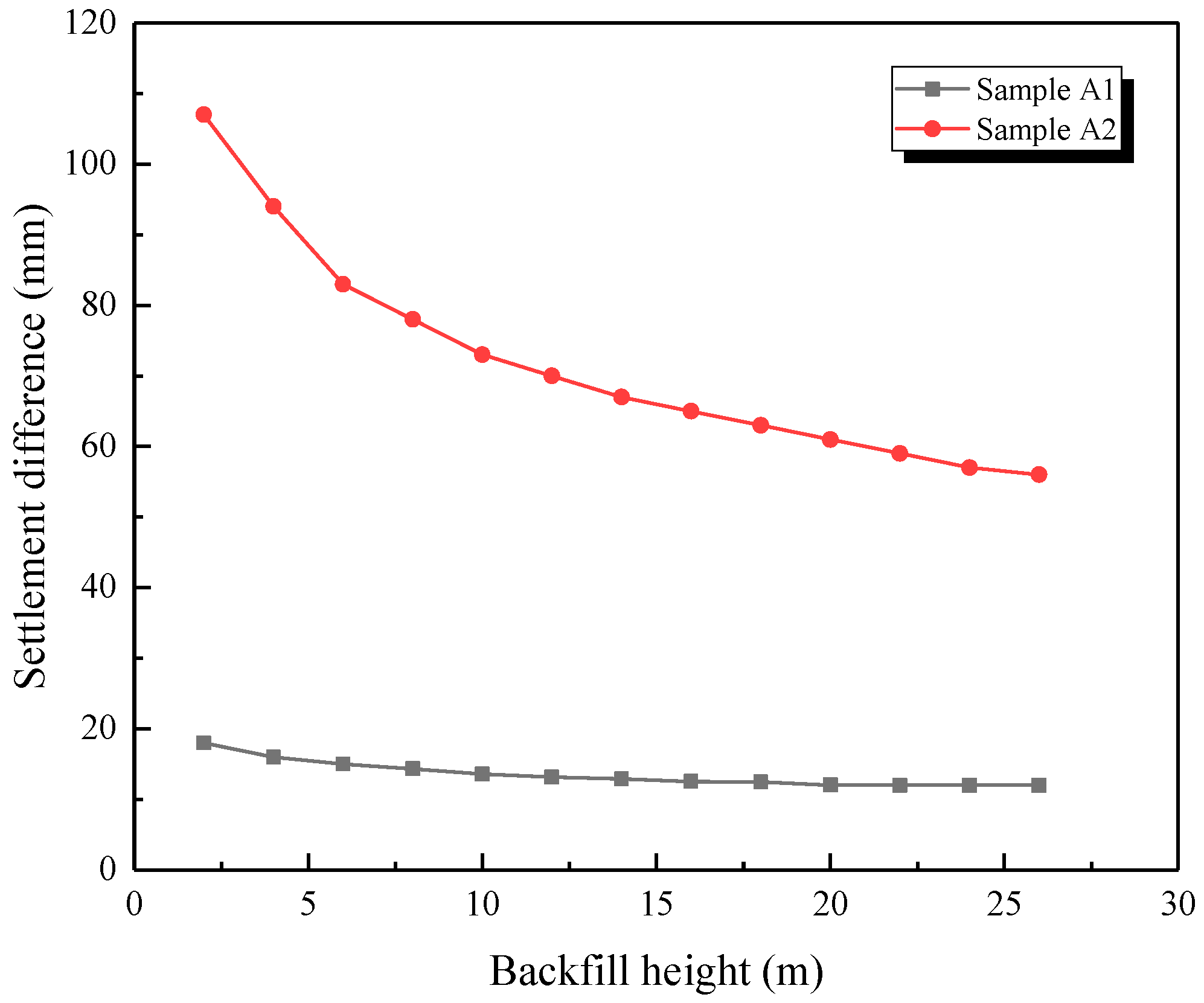
4.3. The Settlement Difference Analysis between the Inside and Outside Soil Columns
5. Internal Force Test Results and Discussion
6. Conclusions
- (1)
- The earth pressure coefficient increased first and then decreased during the backfilling process, and the earth pressure value was significantly higher than the soil column weight. This was because the difference in settlement between the inner and outer soil columns could produce shear forces downward, and the settlement value slowly decreased as the backfill height increased, which was proved by the numerical model above.
- (2)
- At the same backfilling height, the open-cut tunnel on the concrete dam foundation bore greater earth pressure than the one on bedrock, and the internal force of the tunnel on the concrete dam also significantly increased compared with the other one. The lining and the foundation below must be considered as a whole structure to more accurately determine the earth pressure.
- (3)
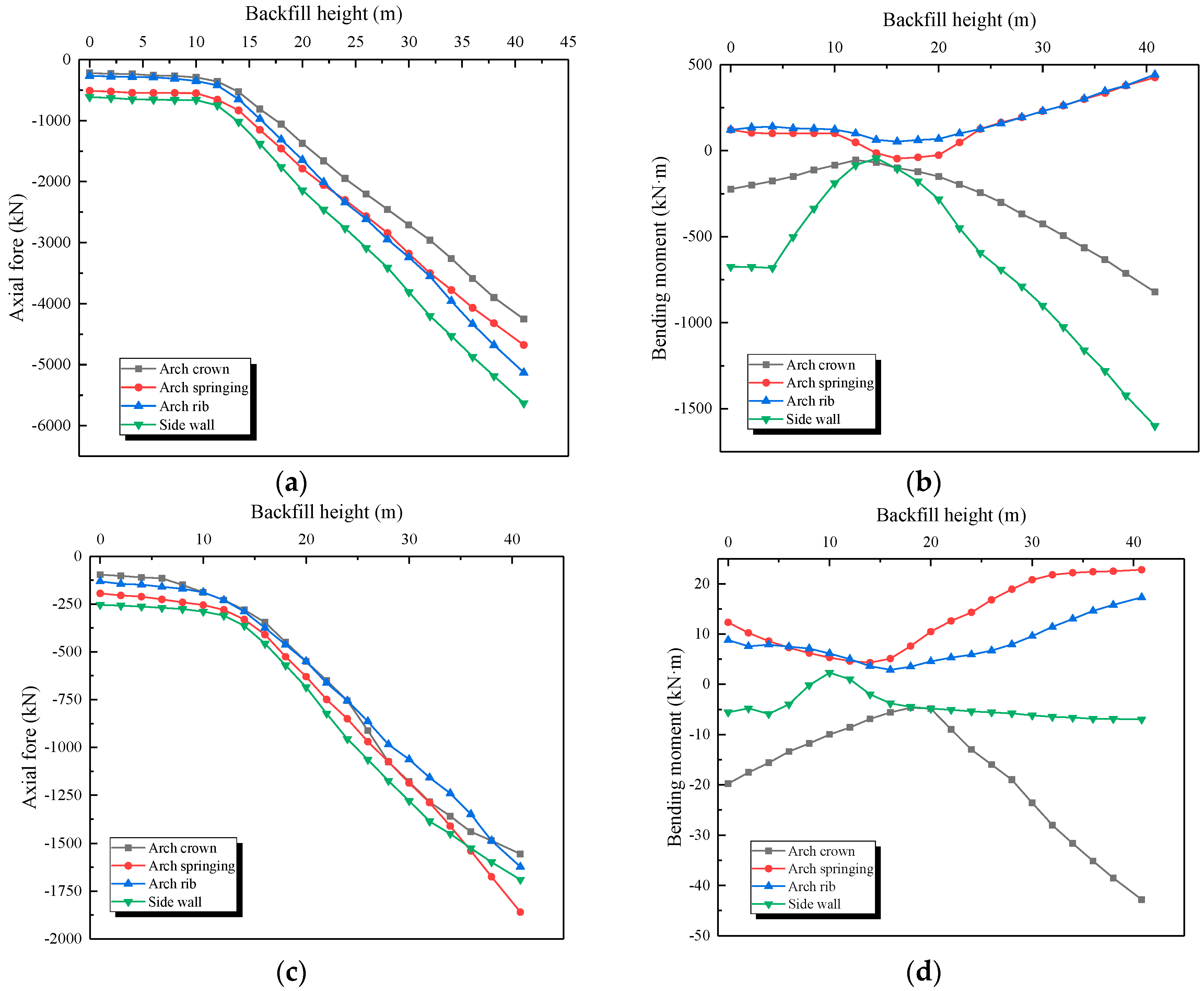
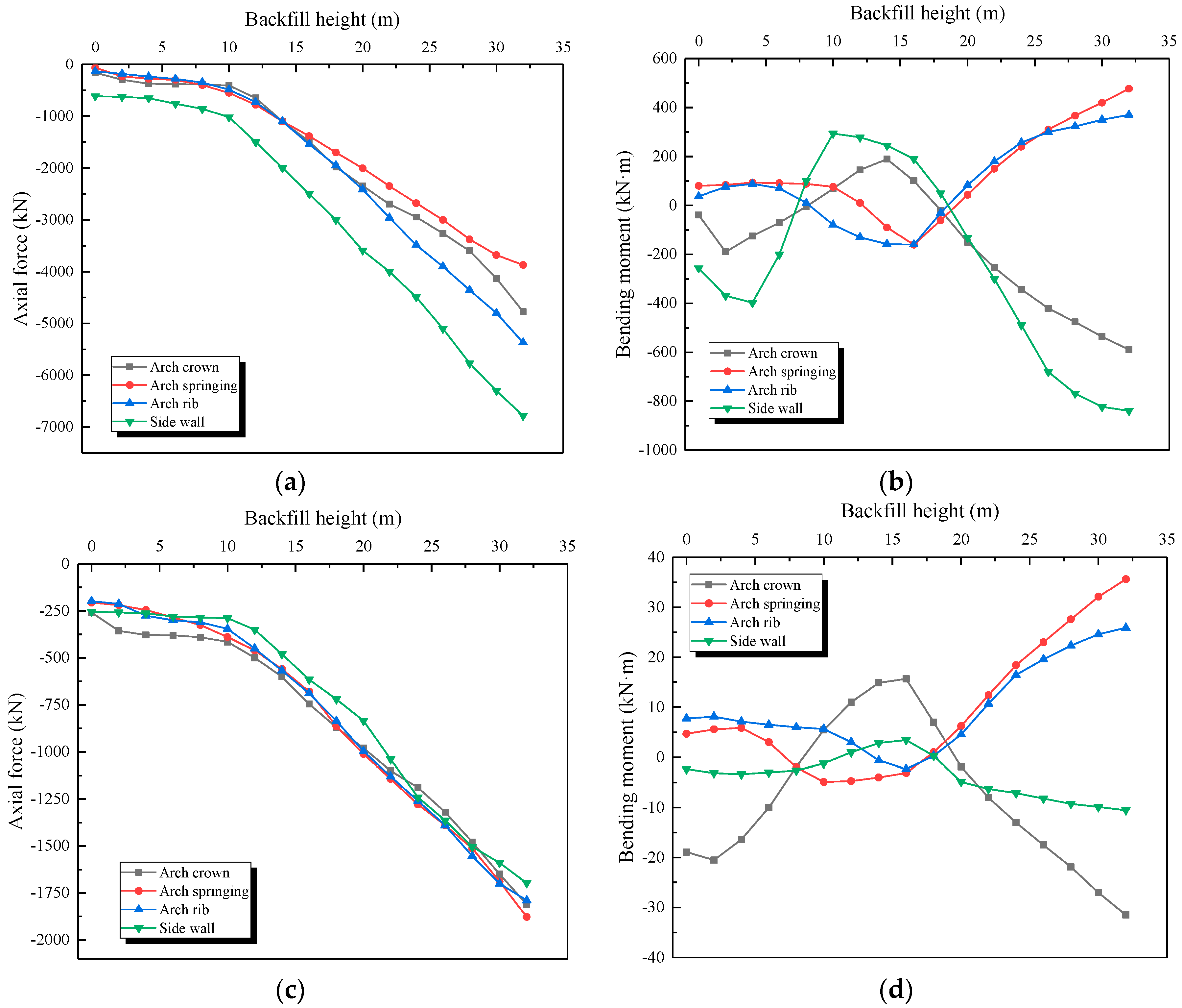
- The change in axial force and bending moment had two stages, and the boundary point was when the soil reached the arch crown. Before that, the axial force and bending moment increased very slowly. When the soil exceeded the arch crown, an obvious linear growth of the absolute value of the internal force was observed.
- (4)
- Because of the low friction coefficient between the inner and outer linings, the transmission of shear force between them was blocked, while the axial force could be transmitted smoothly, indicating that the mechanical behavior of the double lining was quite similar to the combined beam model.
Author Contributions
Funding
Acknowledgments
Conflicts of Interest
References
- Yang, F.; Cao, S.; Qin, G. Mechanical behavior of two kinds of prestressed composite linings: A case study of the Yellow River Crossing Tunnel in China. Tunn. Undergr. Space Technol. 2018, 79, 96–109. [Google Scholar] [CrossRef]
- Vogel, F.; Sovják, R.; Pešková, Š. Static response of double shell concrete lining with a spray-applied waterproofing membrane. Tunn. Undergr. Space Technol. 2017, 68, 106–112. [Google Scholar] [CrossRef]
- Su, J.; Bloodworth, A. Interface parameters of composite sprayed concrete linings in soft ground with spray-applied waterproofing. Tunn. Undergr. Space Technol. 2016, 59, 170–182. [Google Scholar] [CrossRef]
- Su, J.; Bloodworth, A. Numerical calibration of mechanical behavior of composite shell tunnel linings. Tunn. Undergr. Space Technol. 2018, 76, 107–120. [Google Scholar] [CrossRef]
- He, C.; Guo, R.; Xiao, M.; Zhou, J.; He, Y. Model Test on Longitudinal Mechanical Properties of Single and Double Layered Linings for Railway Shield Tunnel. China Railw. Sci. 2013, 34, 40–46. [Google Scholar]
- Yao, C.; Yan, Q.; He, C. An improved analysis model for shield tunnel with double-layer lining and its applications. Chin. J. Rock Mech. Eng. 2014, 33, 80–89. [Google Scholar]
- Ma, Q.; Ku, Z.; Xiao, H.; Hu, B. Calculation of earth pressure on culvert underlying flexible subgrade. Results Phys. 2019, 12, 535–542. [Google Scholar] [CrossRef]
- Li, G.; Ou, J.; Qiu, H.; Wu, J. Mechanism of stress characteristics on surface of slab-culverts under high embankments. Chin. J. Geotech. Eng. 2018, 40, 1152–1160. [Google Scholar]
- Chen, B.; Song, D.; Jiao, J.; Zhang, J. Vertical earth pressure on high fill culverts under load reduction condition. J. Huazhong Univ. Sci. Technol. 2015, 43, 112–116. [Google Scholar]
- Zhang, J.; Zheng, J.; Zhang, T. Experimental Research of Centrifuge Model of Soil Pressure on Positive-buried Box Culvert on Soft Foundation. J. Highw. Transp. Res. Dev. 2014, 07, 53–59. [Google Scholar]
- Shukla, S.K.; Sivakugan, N. Analytical expression for geosynthetic strain due to deflection. Geosynth. Int. 2009, 16, 402–407. [Google Scholar] [CrossRef]
- Kim, K.; Yoo, C.H. Design loading on deeply buried box culverts. J. Geotech. Geo-Environ. Eng. 2005, 131, 20–27. [Google Scholar] [CrossRef]
- Meguid, M.A.; Youssef, T.A. Youssef. Experimental investigation of the earth pressure distribution on buried pipes backfilled with tire-derived aggregate. Transp. Geotech. 2018, 14, 117–125. [Google Scholar] [CrossRef]
- Kang, J.; Parker, F.; Yoo, C.H. Soil–structure interaction for deeply buried corrugated steel pipes Part II: Imperfect trench installation. Eng. Struct. 2008, 30, 588–594. [Google Scholar] [CrossRef]
- Kheradi, H.; Ye, B.; Nishi, H.; Oka, R.; Zhang, F. Optimum pattern of ground improvement for enhancing seismic resistance of existing box culvert buried in soft ground. Tunn. Undergr. Space Technol. 2017, 69, 187–202. [Google Scholar] [CrossRef]
- Kaklauskas, G.; Sokolov, A.; Ramanauskas, R. Ronaldas Jakubovskis Reinforcement Strains in Reinforced Concrete Tensile Members Recorded by Strain Gauges and FBG Sensors: Experimental and Numerical Analysis. Sensors 2019, 19, 200. [Google Scholar] [CrossRef] [PubMed]
- Tsuda, H.; Kumakura, K.; Ogihara, S. Ultrasonic sensitivity of strain-insensitive fiber Bragg grating sensors and evaluation of ultrasound-induced strain. Sensors 2010, 10, 11248–11258. [Google Scholar] [CrossRef]
- Xu, D. A new measurement approach for small deformations of soil specimens using fiber bragg grating sensors. Sensors 2017, 17, 1016. [Google Scholar] [CrossRef]
- Her, S.C.; Huang, C.Y. Effect of coating on the strain transfer of optical fiber sensors. Sensors 2011, 11, 6926–6941. [Google Scholar] [CrossRef] [PubMed]
- Campopiano, S.; Cutolo, A.; Cusano, A.; Giordano, M.; Parente, G.; Lanza, G.; Laudati, A. Underwater acoustic sensors based on fiber Bragg gratings. Sensors 2009, 9, 4446–4454. [Google Scholar] [CrossRef]
- Ho, S.C.M.; Ren, L.; Li, H.N.; Song, G. A fiber Bragg grating sensor for detection of liquid water in concrete structures. Smart Mater. Struct. 2013, 22, 055012. [Google Scholar] [CrossRef]
- Costa, B.J.; Figueiras, J.A. Figueiras, Fiber optic based monitoring system applied to a centenary metallic arch bridge: Design and installation. Eng. Struct. 2012, 44, 271–280. [Google Scholar] [CrossRef]
- Xiao, F.; Chen, G.; Hulsey, J. Monitoring Bridge Dynamic Responses Using Fiber Bragg Grating Tiltmeters. Sensors 2017, 17, 2390. [Google Scholar] [CrossRef] [PubMed]
- Li, Z.; Xu, T.; Wu, Q.; Yu, L.; Wang, M. Field experimental study of basement structural dynamic properties of the heavy-haul railway tunnel in broken surrounding rock. Rock Soil Mech. 2018, 39, 949–956. [Google Scholar]
- Li, Z.; Wang, M.; Yu, L.; Zhao, Y. Study of the basement structure load under the dynamic loading of heavy-haul railway tunnel. Int. J. Pavement Eng. 2018. [Google Scholar] [CrossRef]
- Dong, L.; Tong, X.; Li, X.; Zhou, J.; Wang, S.; Liu, B. Some developments and new insights of environmental problems and deep mining strategy for cleaner production in mines. J. Clean. Prod. 2019, 210, 1562–1578. [Google Scholar] [CrossRef]
- Rodrigues, C.; Cavadas, F.; Félix, C.; Figueiras, J. FBG based strain monitoring in the rehabilitation of a centenary metallic bridge. Eng. Struct. 2012, 44, 281–290. [Google Scholar] [CrossRef]
- Shi, S.; Xie, X.; Wen, Z.; Zhou, Z.; Li, L.; Song, S.; Wu, Z. Intelligent Evaluation System of Water Inrush in Roadway (Tunnel) and Its Application. Water 2018, 10, 997. [Google Scholar] [CrossRef]
- Dong, L.; Li, X.; Xu, M.; Li, Q. Comparisons of Random Forest and Support Vector Machine for Predicting Blasting Vibration Characteristic Parameters. Procedia Eng. 2011, 26, 1772–1781. [Google Scholar]
- Wang, G. Elastic Mechanics, 3rd ed.; Higher Education Press: Beijing, China, 2015; pp. 106–107. [Google Scholar]
- Jiang, C.; Chen, B.; Mao, X.; She, M. Stress characteristics of high fill load-shedding culvert on flexible foundation. Rocks Soil Mech. 2019, 01, 1–6. [Google Scholar]
- Chen, B.; Song, D.; Mao, X.; Chen, E.J.; Zhang, J. Model Test and Numerical Simulation on Rigid Load shedding Culvert Backfilled with Sand. Comput. Geotech. 2016, 79, 31–40. [Google Scholar] [CrossRef]


| Project Name | Backfill Height—From Tunnel Crown to Backfill Surface (m) | Lining Thickness (m) |
|---|---|---|
| Lanyu open-cut tunnel | 40 | 1.8–2.4 |
| Longdongbao open-cut tunnel | 33 | 2.8–3.0 |
| Fengdu open-cut tunnel | 28 | 1.9–3.3 |
| Type | Backfill Height | Foundation Form |
|---|---|---|
| Sample A1 | 28.0 m | Bedrock with weatherproof protection |
| Sample A2 | 22.0 m | C30 Concrete dam |
| Object | Elastic Modulus | Density | Poisson Ratio | Cohesion | Internal Friction Angle |
|---|---|---|---|---|---|
| Backfill | 12.6 MPa | 2100 kg/m3 | 0.4 | 0.1 MPa | 22° |
| Bedrock | 7.25 GPa | 2300 kg/m3 | 0.32 | 0.2 MPa | 31° |
| Lining | 33.5 GPa | 2500 kg/m3 | 0.2 | ||
| Dam | 31.5 GPa | 2500 kg/m3 | 0.2 |
| Position | Sample A1 | Sample A2 | Times (A2/A1) |
|---|---|---|---|
| Arch crown | 1.404 | 2.15 | 1.53 |
| Arch rib | 1.341 | 2.278 | 1.69 |
| Position | Sample A1 | Sample A2 | Times (A2/A1) |
|---|---|---|---|
| Arch crown | 1.292 | 2.104 | 1.63 |
| Arch rib | 1.281 | 2.037 | 1.59 |
| Object | Outer/Inner Lining | Foundation Type | Arch Crown | Arch Rib | Arch Springing | Side Wall |
|---|---|---|---|---|---|---|
| Axial force (kN) | Outer lining | Bedrock | −2960.13 | −3552.58 | −3504.25 | −4200.27 |
| Concrete dam | −4772.29 | −5367.43 | −5807.45 | −6781.54 | ||
| Inner lining | Bedrock | −1286 | −1158 | −1289 | −1386 | |
| Concrete dam | −1810 | −1789 | −1878 | −1698 | ||
| Bending moment (kN·m) | Outer lining | Bedrock | −492.94 | 262.17 | 512.23 | −1025.67 |
| Concrete dam | −987.53 | 547.12 | 918.45 | −1775.46 | ||
| Inner lining | Bedrock | −28 | 11.42 | 21.8 | −6.5 | |
| Concrete dam | −68.52 | 25.89 | 35.6 | −10.53 |
© 2019 by the authors. Licensee MDPI, Basel, Switzerland. This article is an open access article distributed under the terms and conditions of the Creative Commons Attribution (CC BY) license (http://creativecommons.org/licenses/by/4.0/).
Share and Cite
Xu, T.; Wang, M.; Yu, L.; Lv, C.; Dong, Y.; Tian, Y. Research on the Earth Pressure and Internal Force of a High-Fill Open-Cut Tunnel Using a Bilayer Lining Design: A Field Test Using an FBG Automatic Data Acquisition System. Sensors 2019, 19, 1487. https://doi.org/10.3390/s19071487
Xu T, Wang M, Yu L, Lv C, Dong Y, Tian Y. Research on the Earth Pressure and Internal Force of a High-Fill Open-Cut Tunnel Using a Bilayer Lining Design: A Field Test Using an FBG Automatic Data Acquisition System. Sensors. 2019; 19(7):1487. https://doi.org/10.3390/s19071487
Chicago/Turabian StyleXu, Tianyuan, Mingnian Wang, Li Yu, Cheng Lv, Yucang Dong, and Yuan Tian. 2019. "Research on the Earth Pressure and Internal Force of a High-Fill Open-Cut Tunnel Using a Bilayer Lining Design: A Field Test Using an FBG Automatic Data Acquisition System" Sensors 19, no. 7: 1487. https://doi.org/10.3390/s19071487
APA StyleXu, T., Wang, M., Yu, L., Lv, C., Dong, Y., & Tian, Y. (2019). Research on the Earth Pressure and Internal Force of a High-Fill Open-Cut Tunnel Using a Bilayer Lining Design: A Field Test Using an FBG Automatic Data Acquisition System. Sensors, 19(7), 1487. https://doi.org/10.3390/s19071487