A Fire Reconnaissance Robot Based on SLAM Position, Thermal Imaging Technologies, and AR Display

Abstract
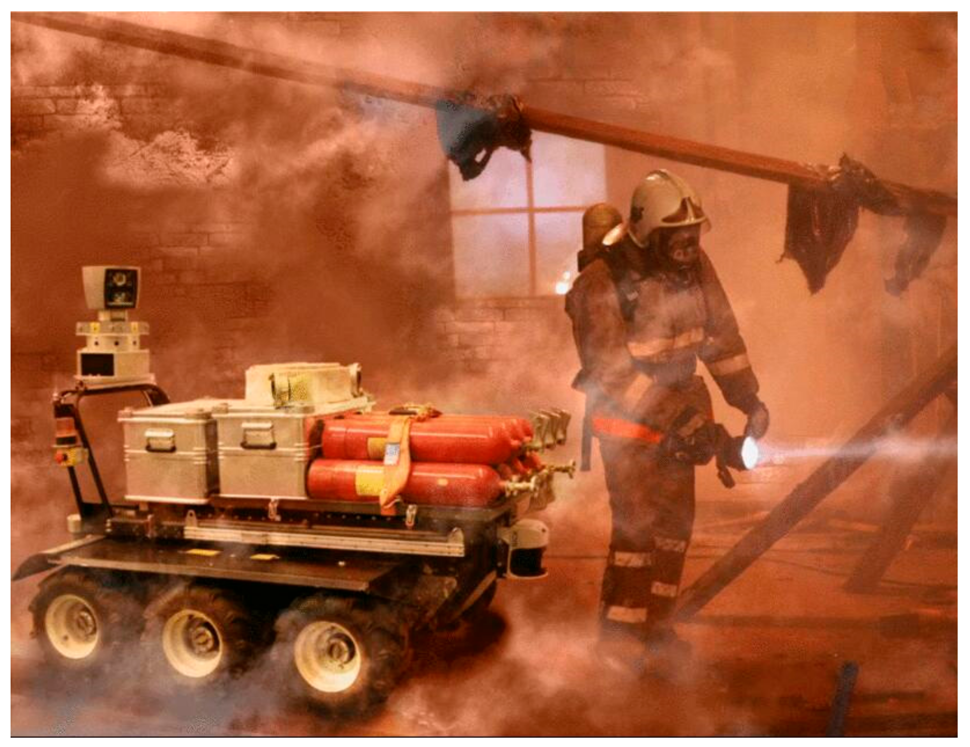
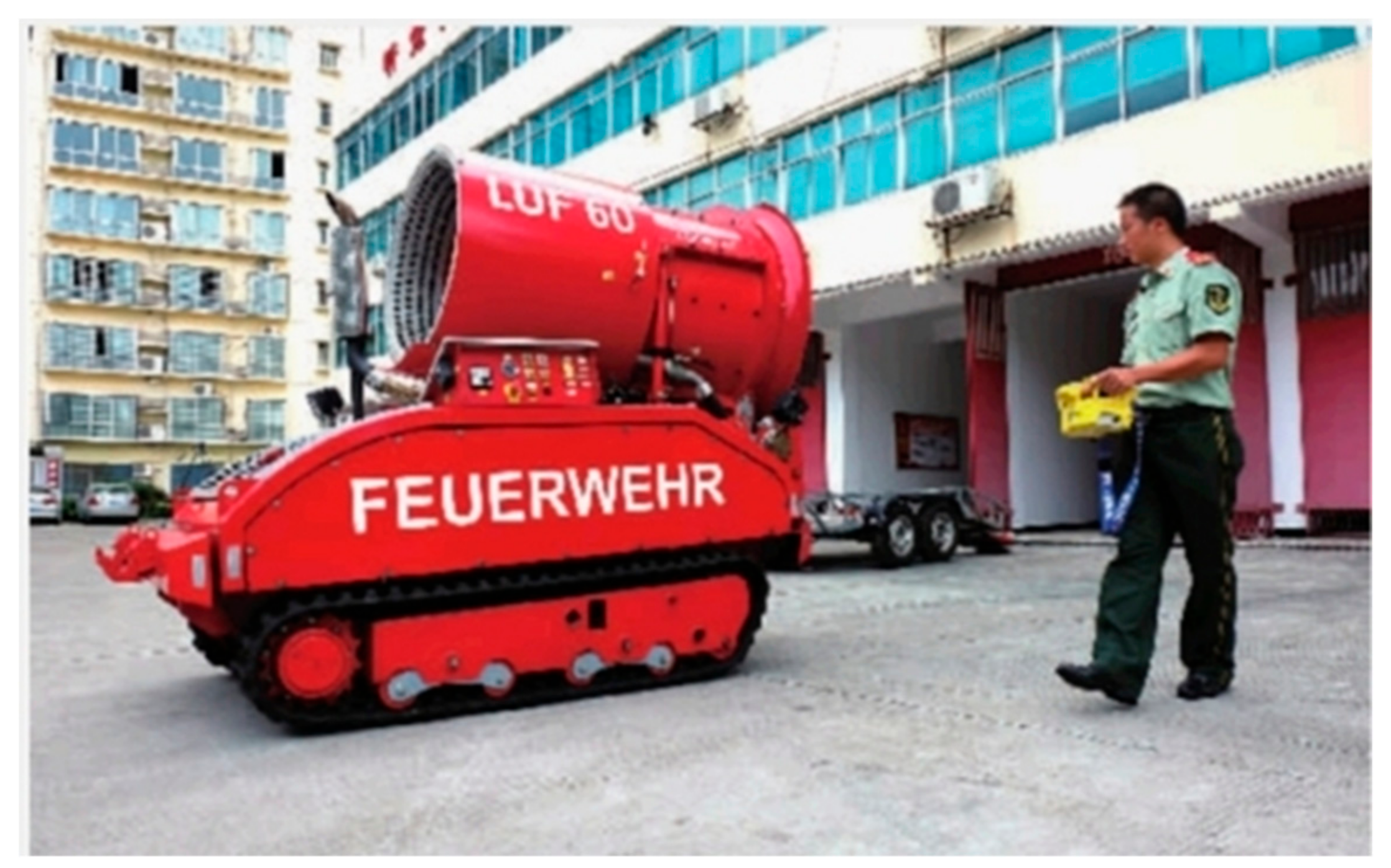
1. Introduction
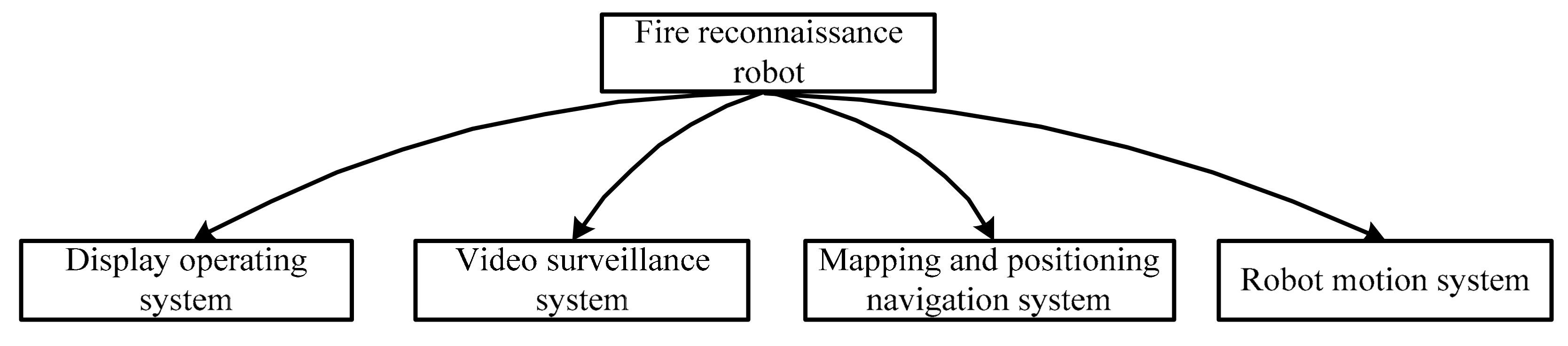
2. Description of the Robot System
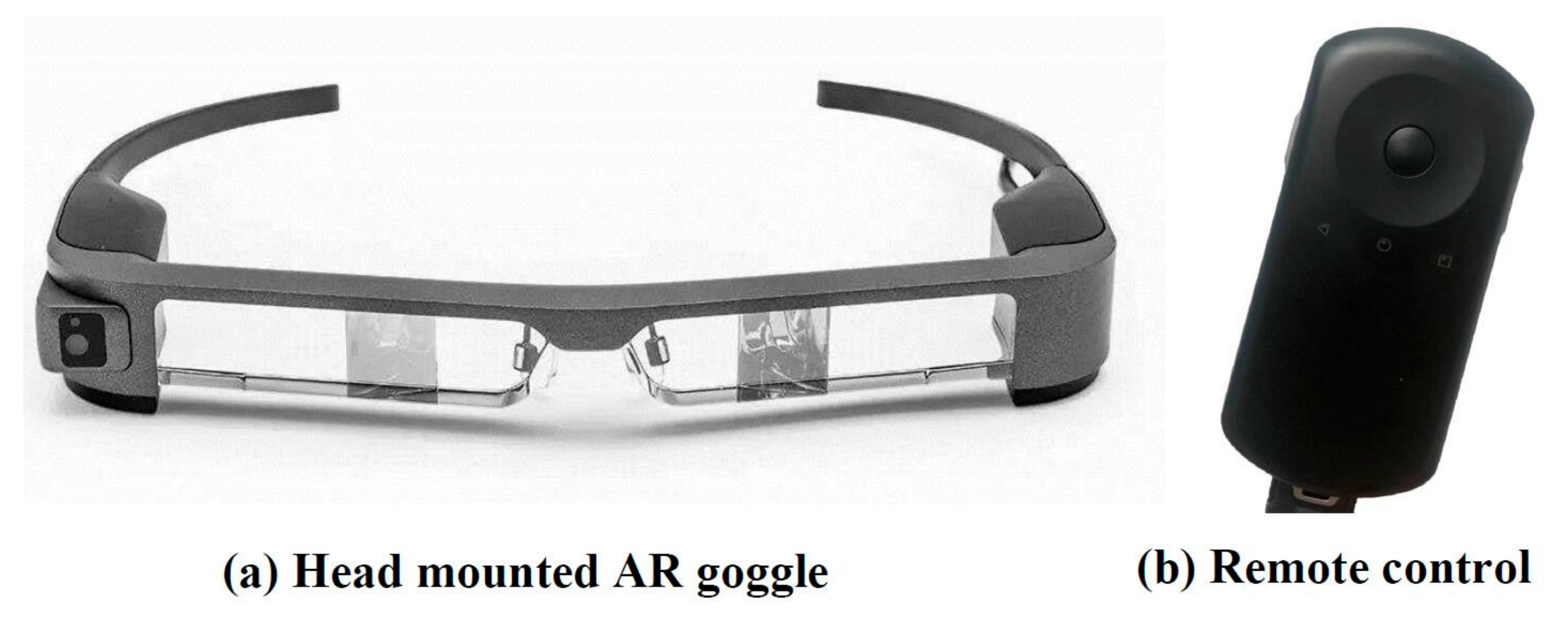
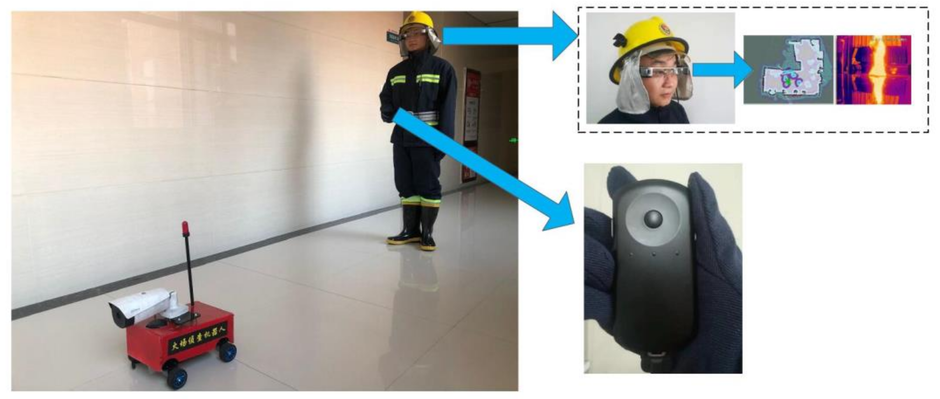
2.1. Display Operation System
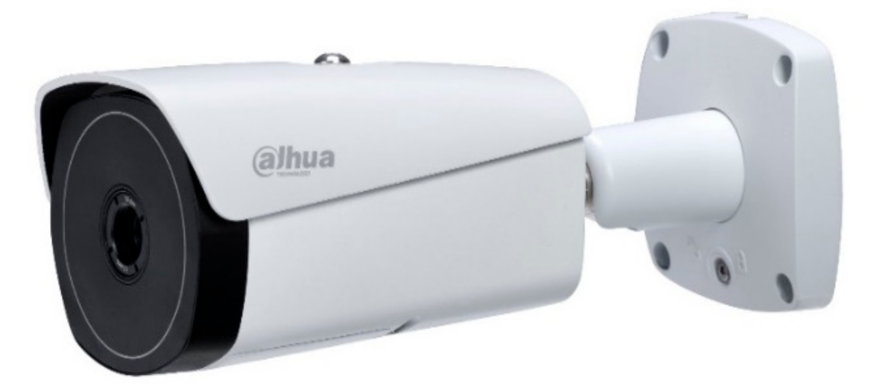
2.2. Video Surveillance System
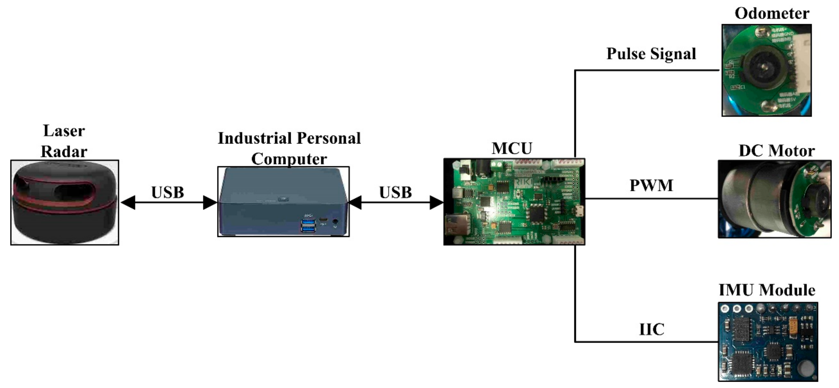
2.3. Mapping and Positioning Navigation System
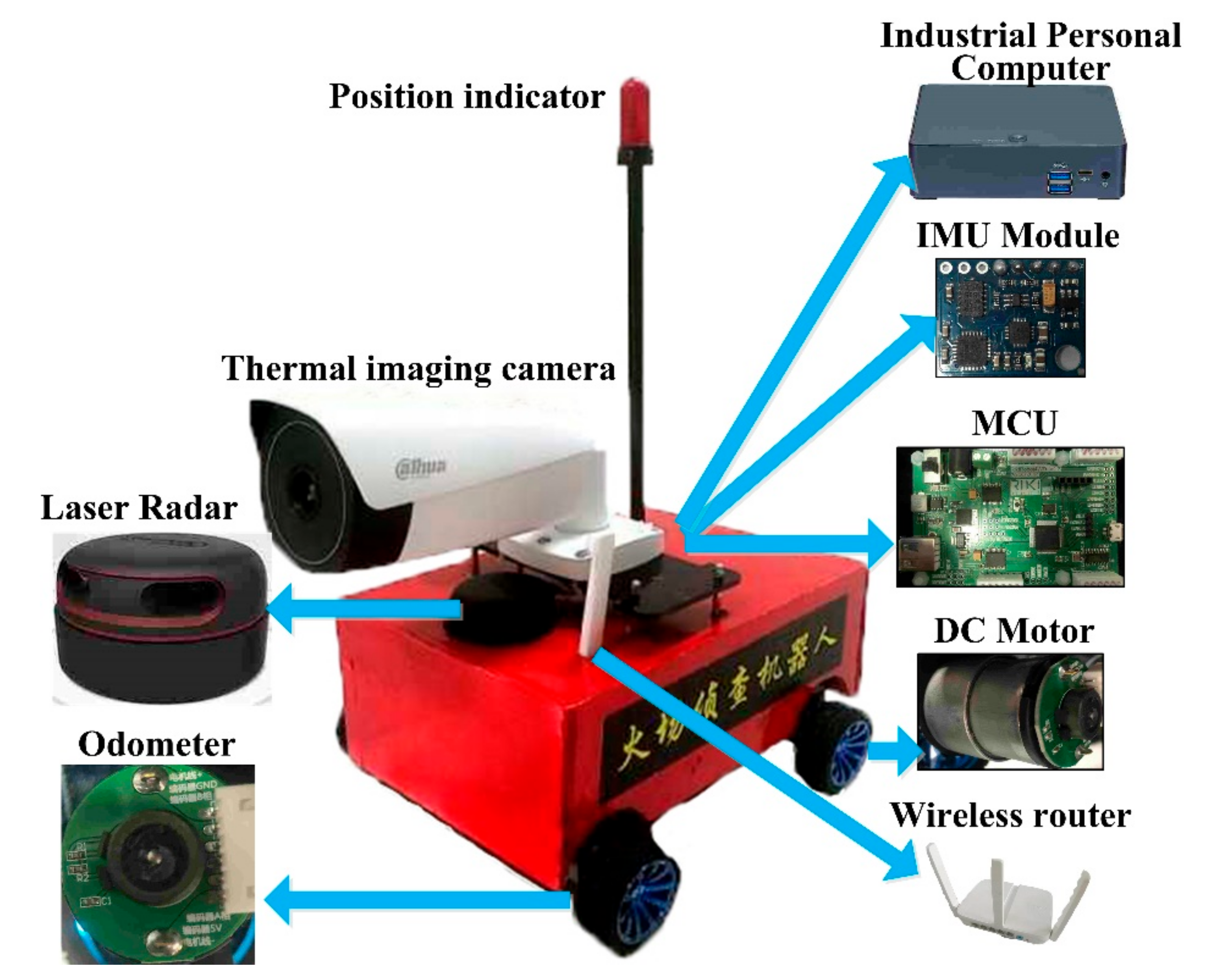
2.4. The Overall Fire Reconnaissance Robot System
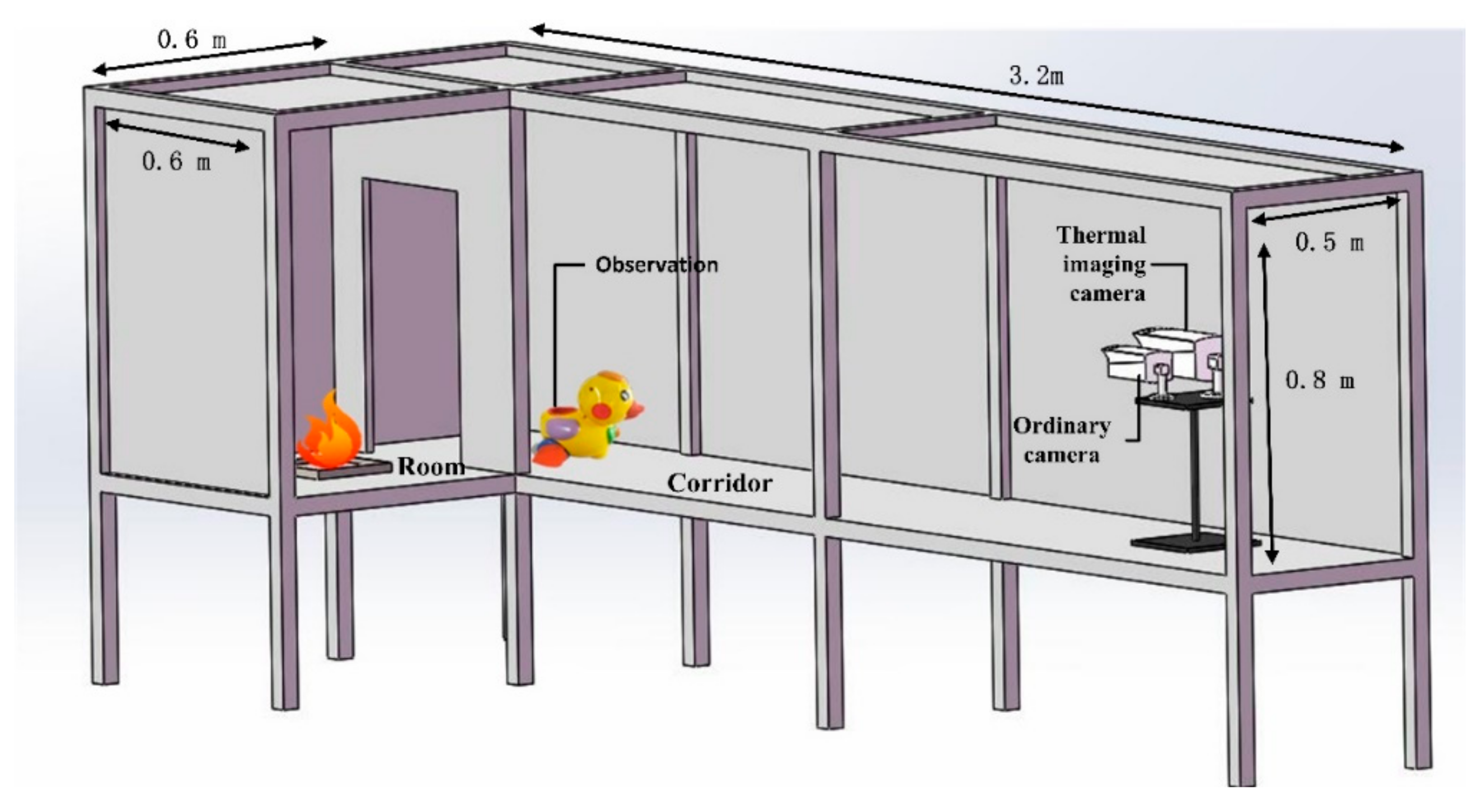
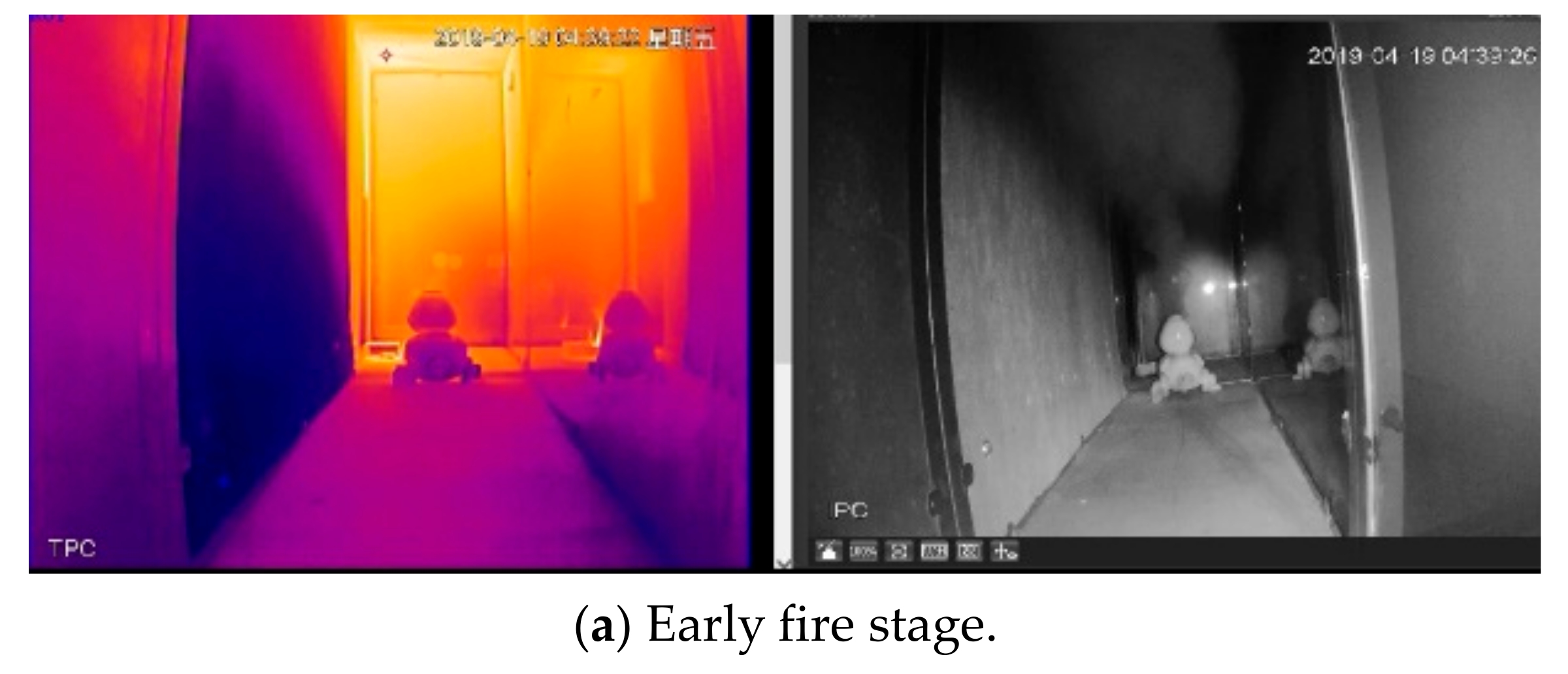
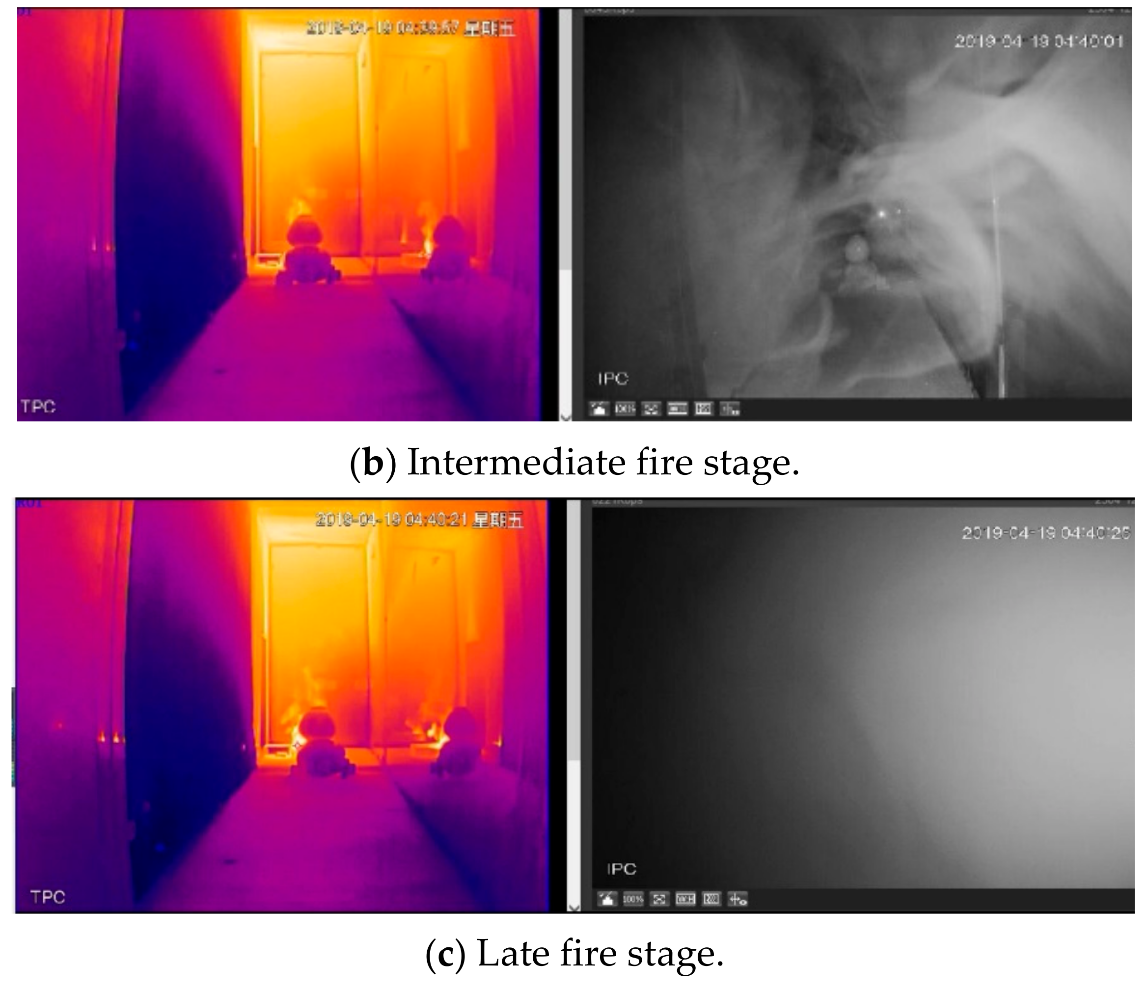
3. Performance Test of the Video Surveillance System
4. Performance Test of the Mapping and Positioning Navigation System
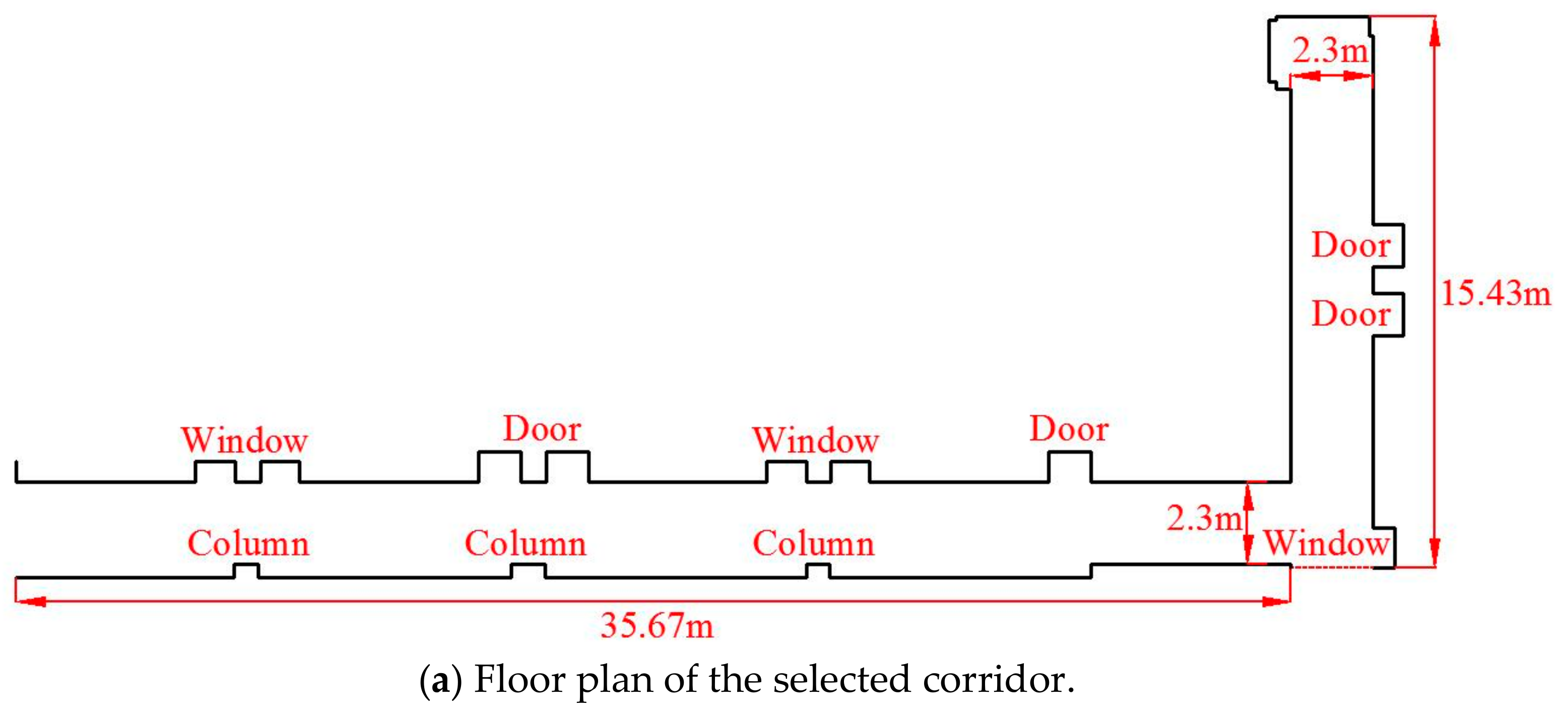
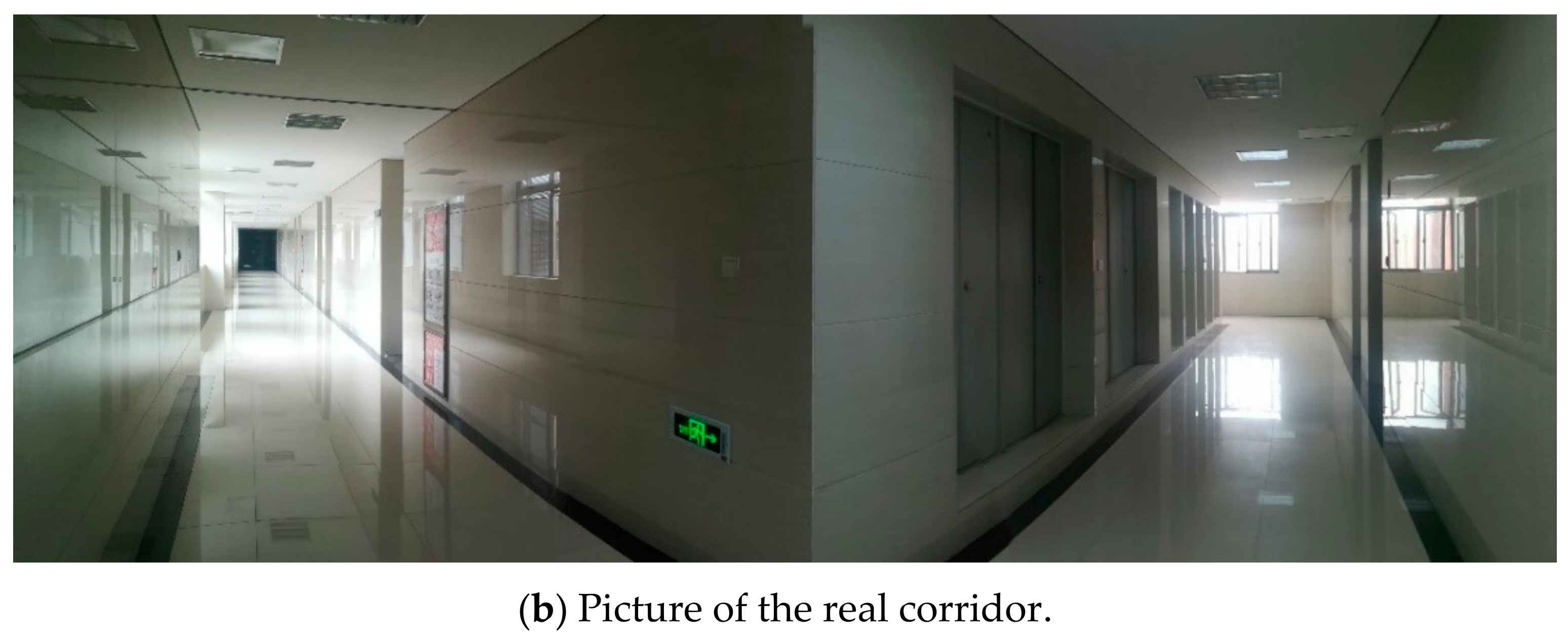
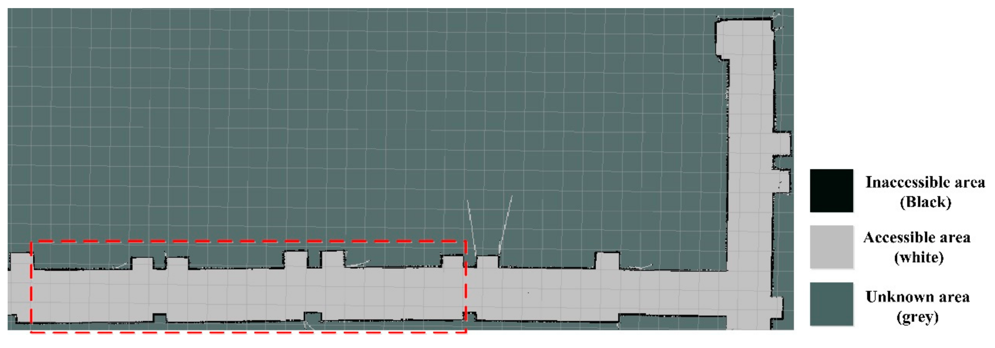
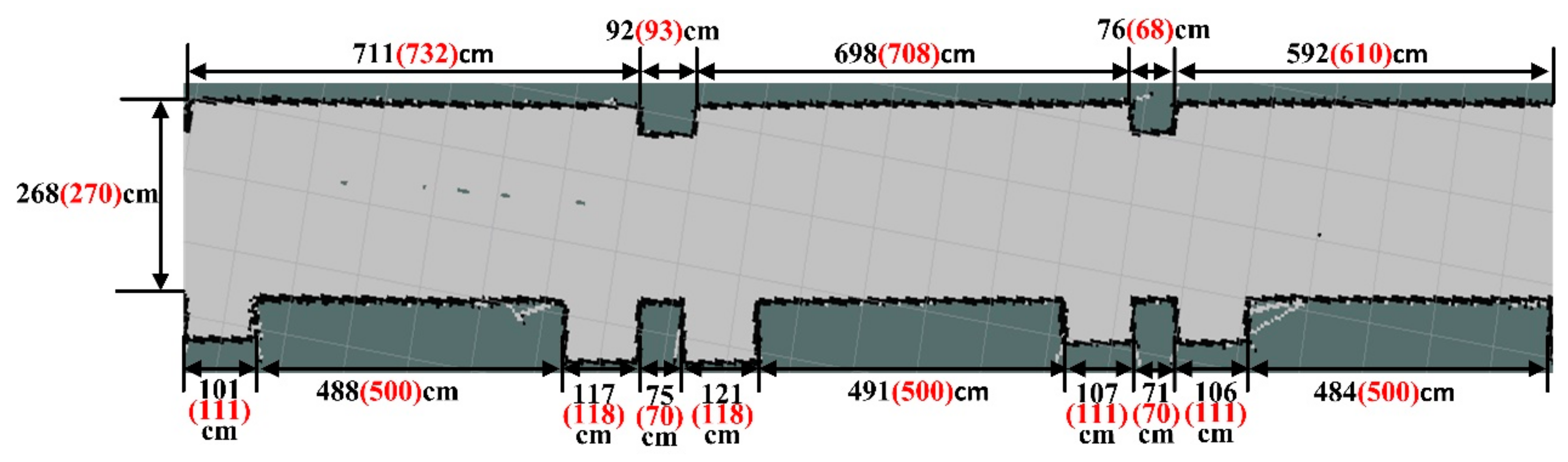
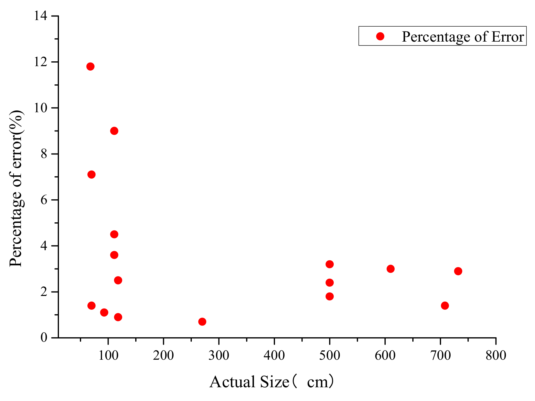
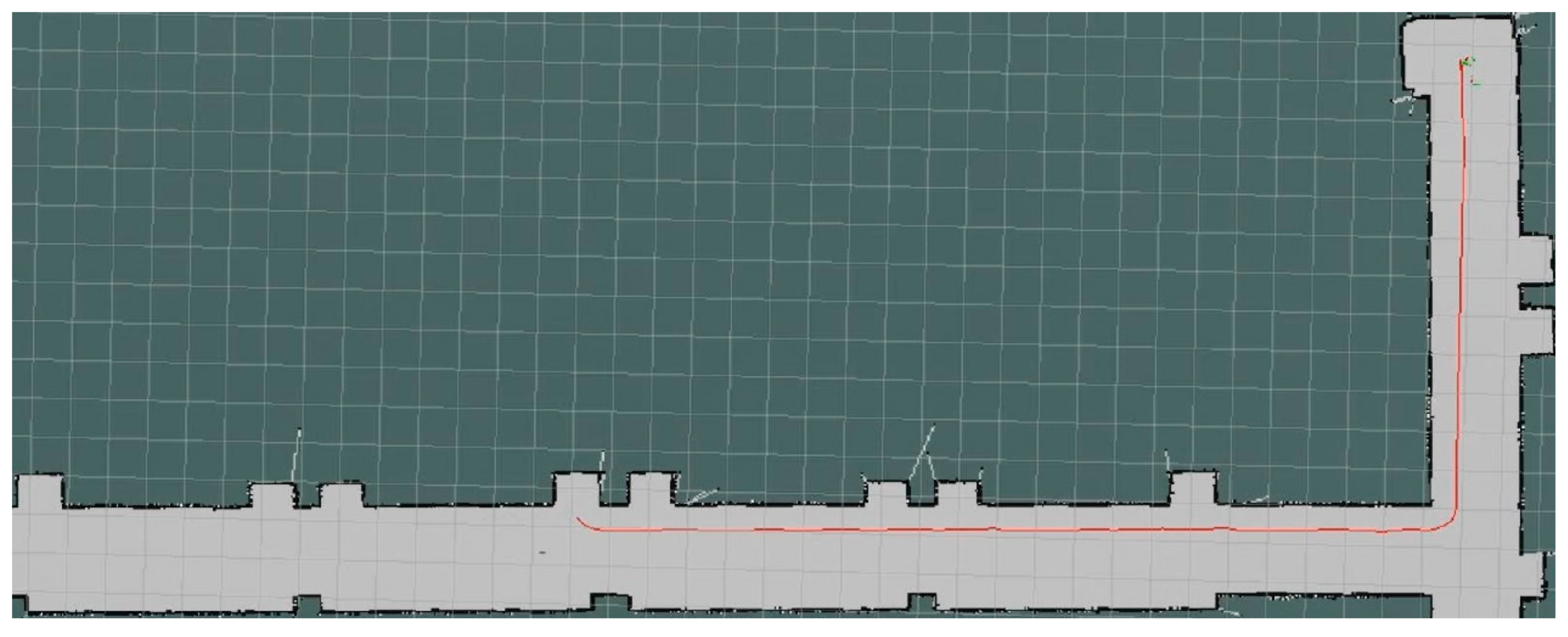
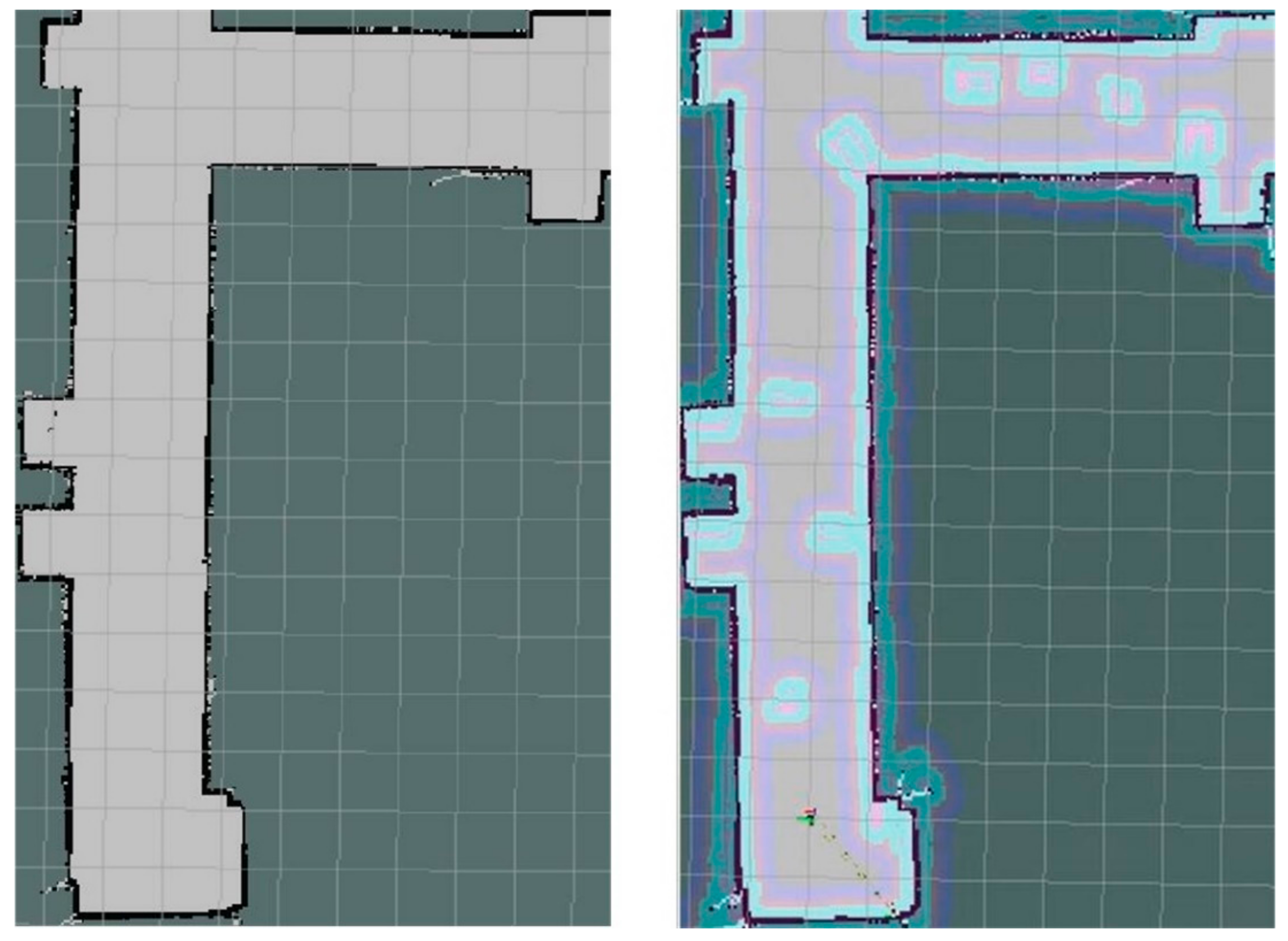
4.1. The Accuracy of Mapping Construction
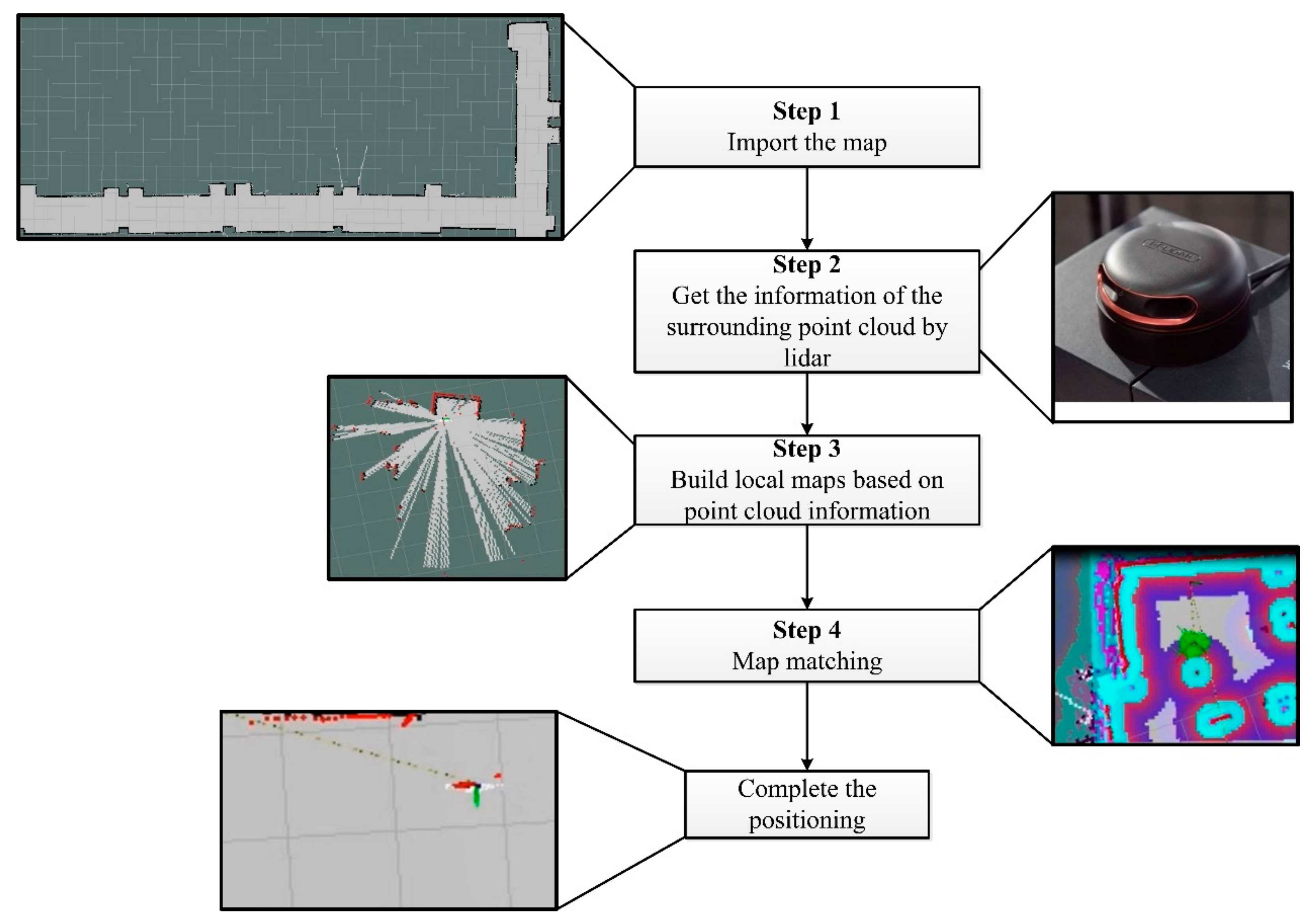
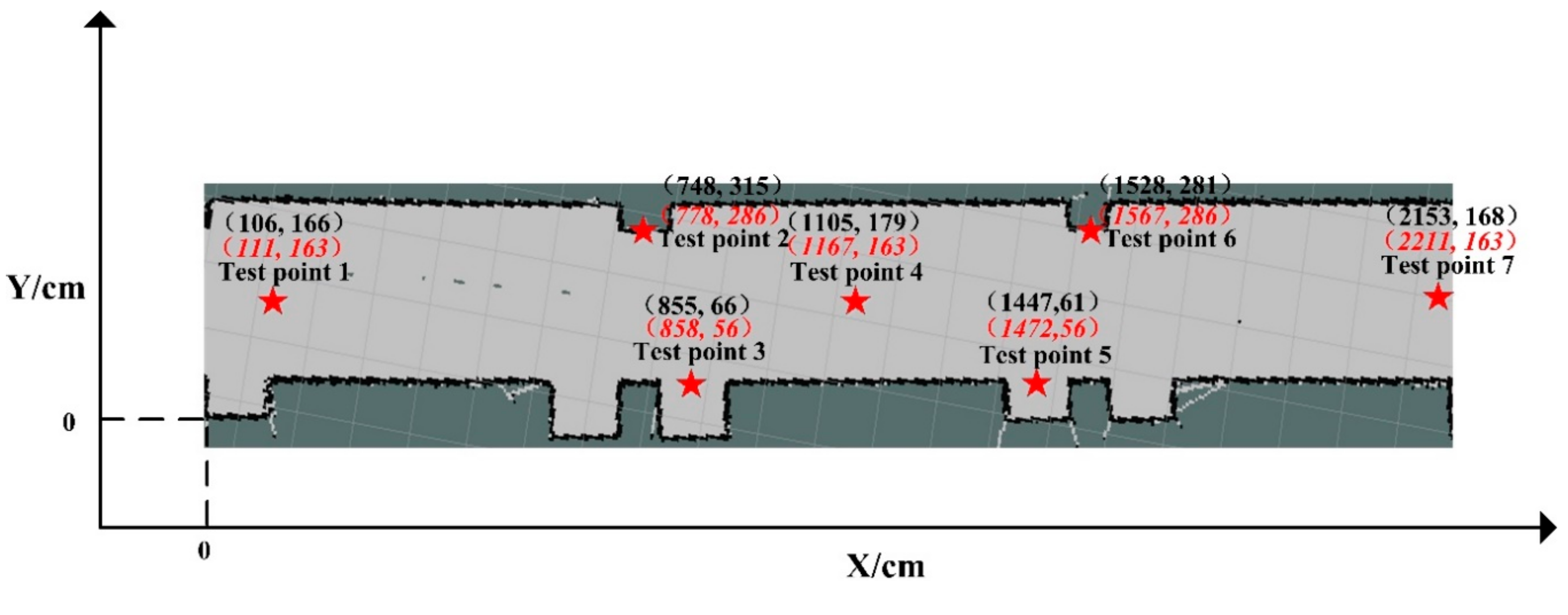
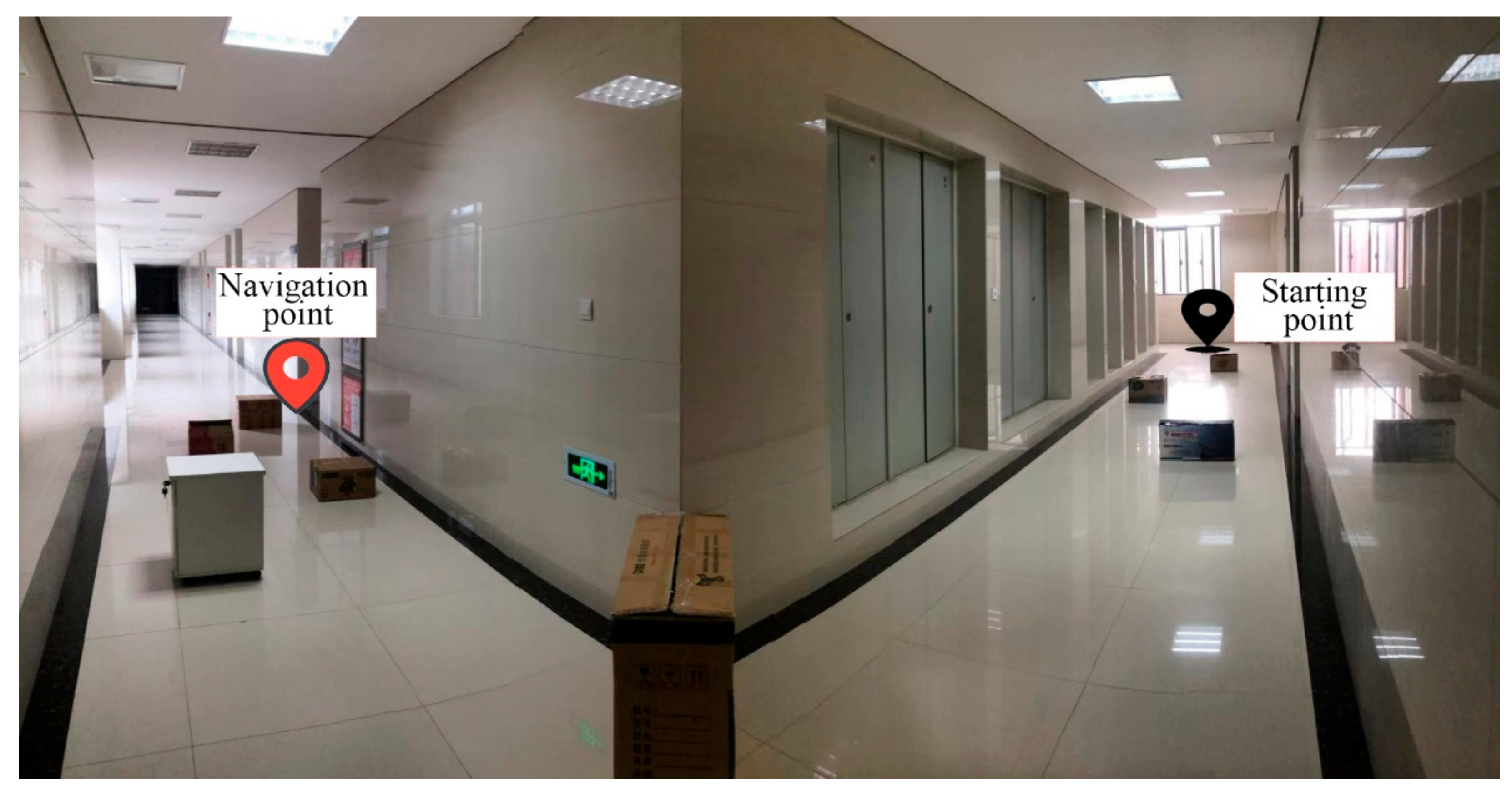
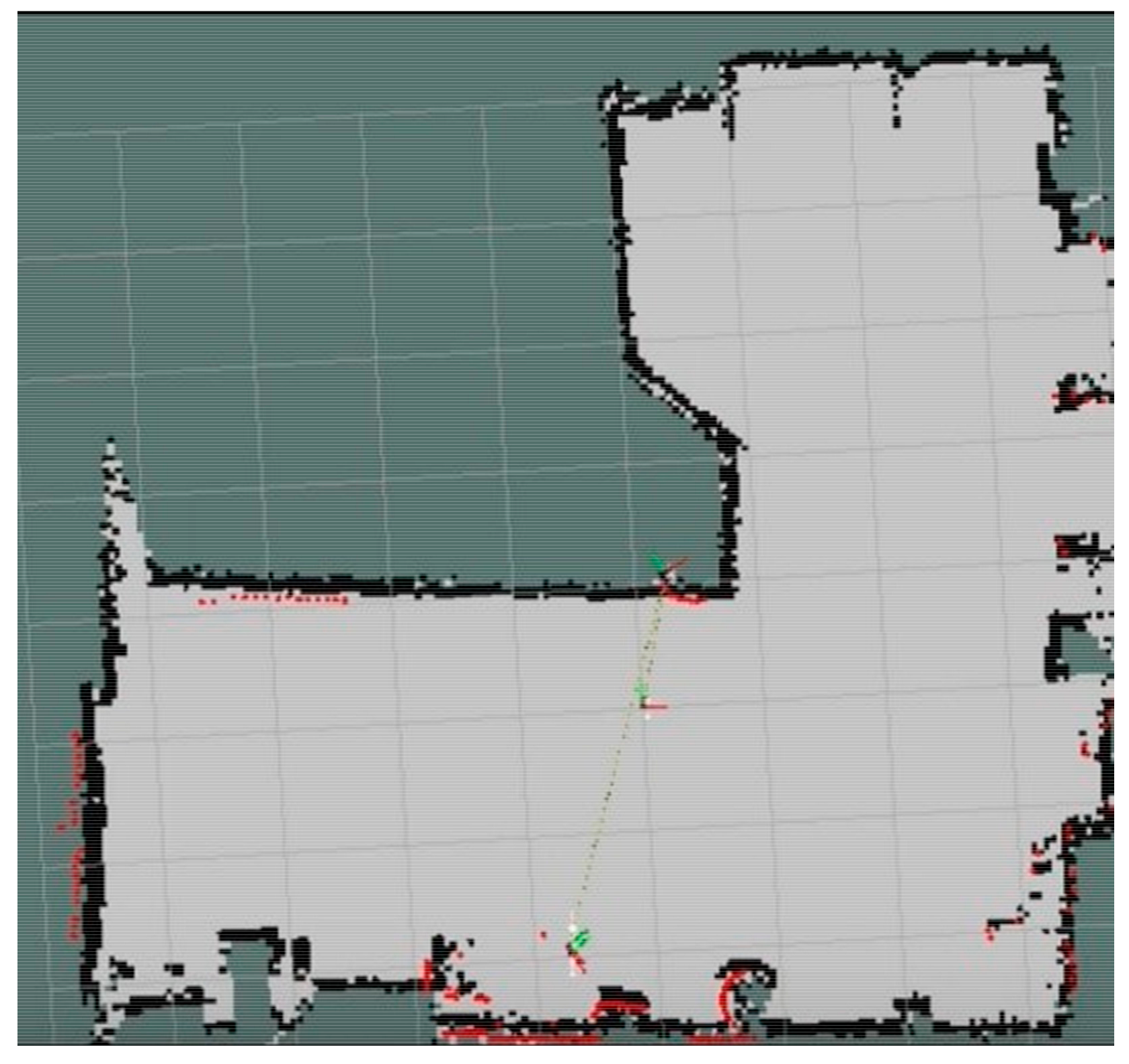
4.2. Accuracy Test of the Indoor Positioning
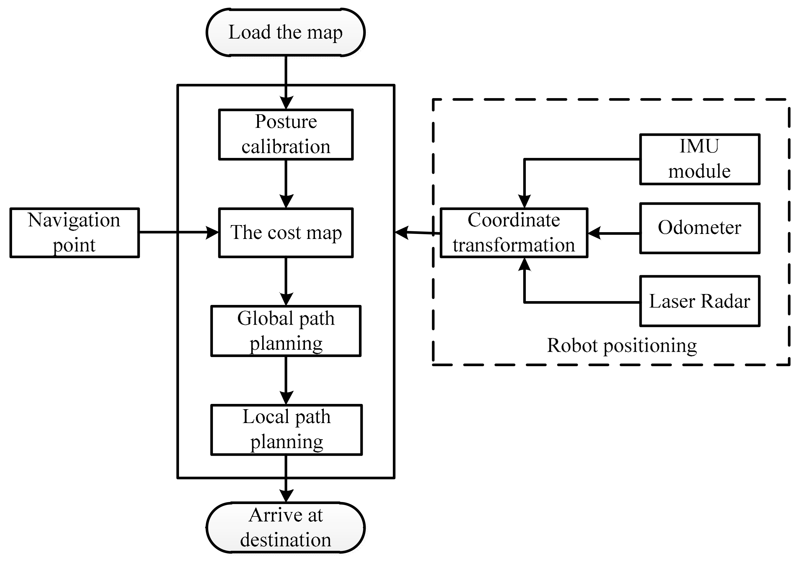
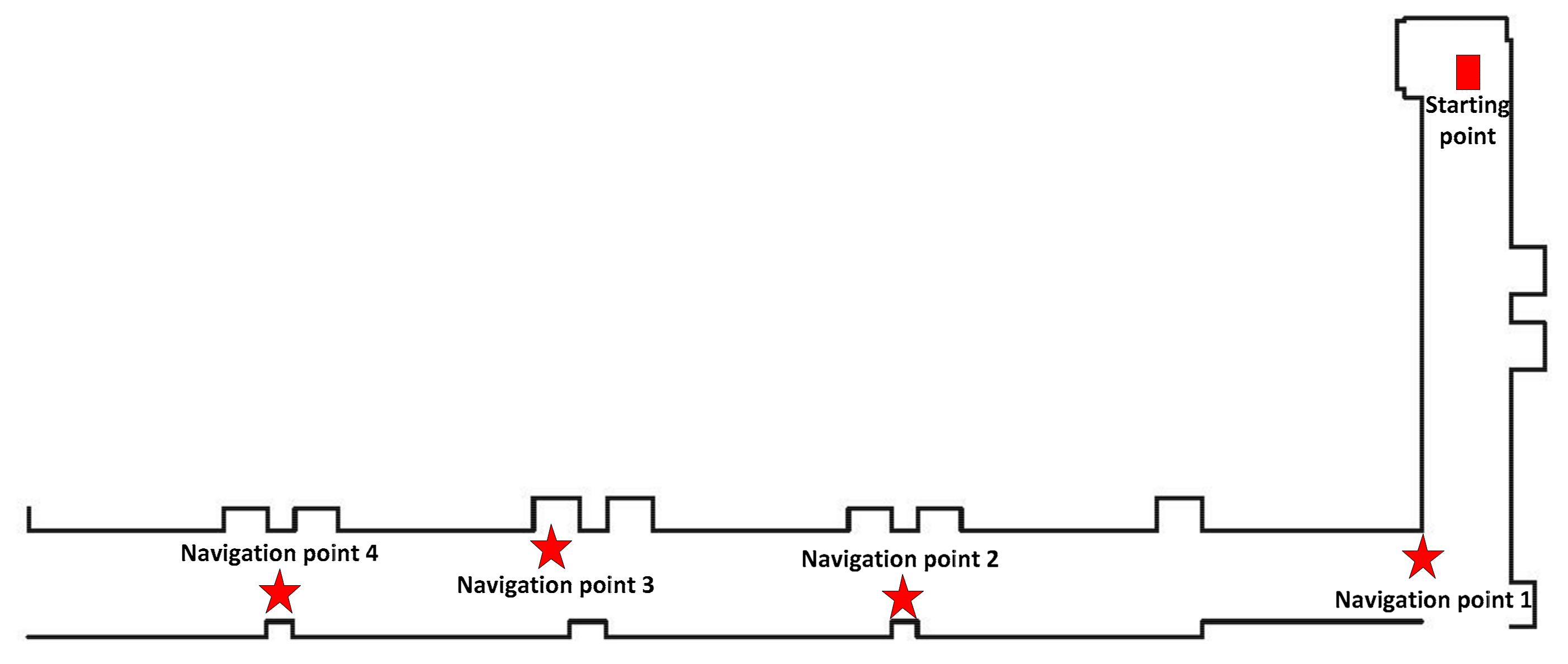
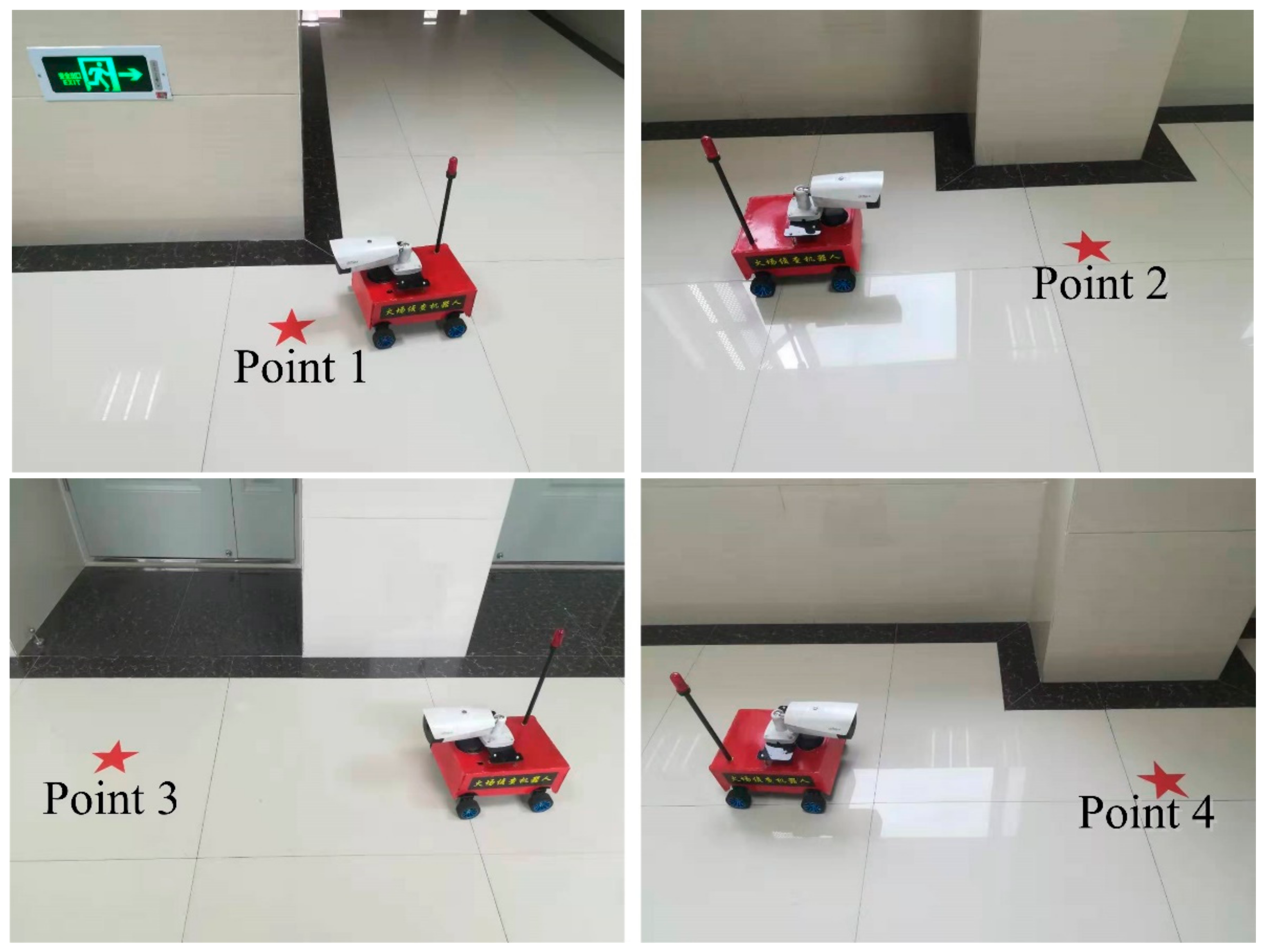
4.3. The Accuracy of Navigation
4.3.1. Obstacle-Free Navigation
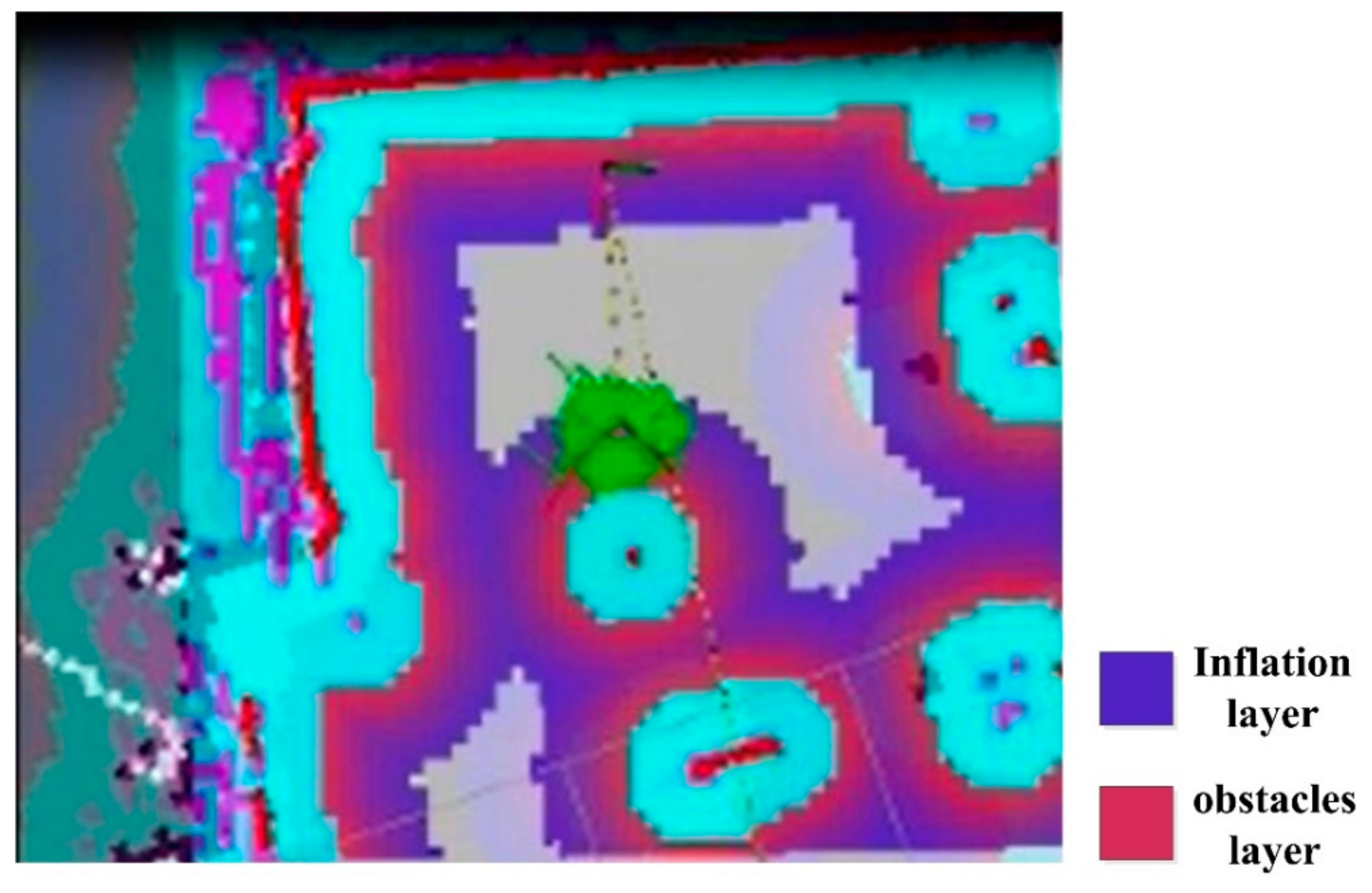
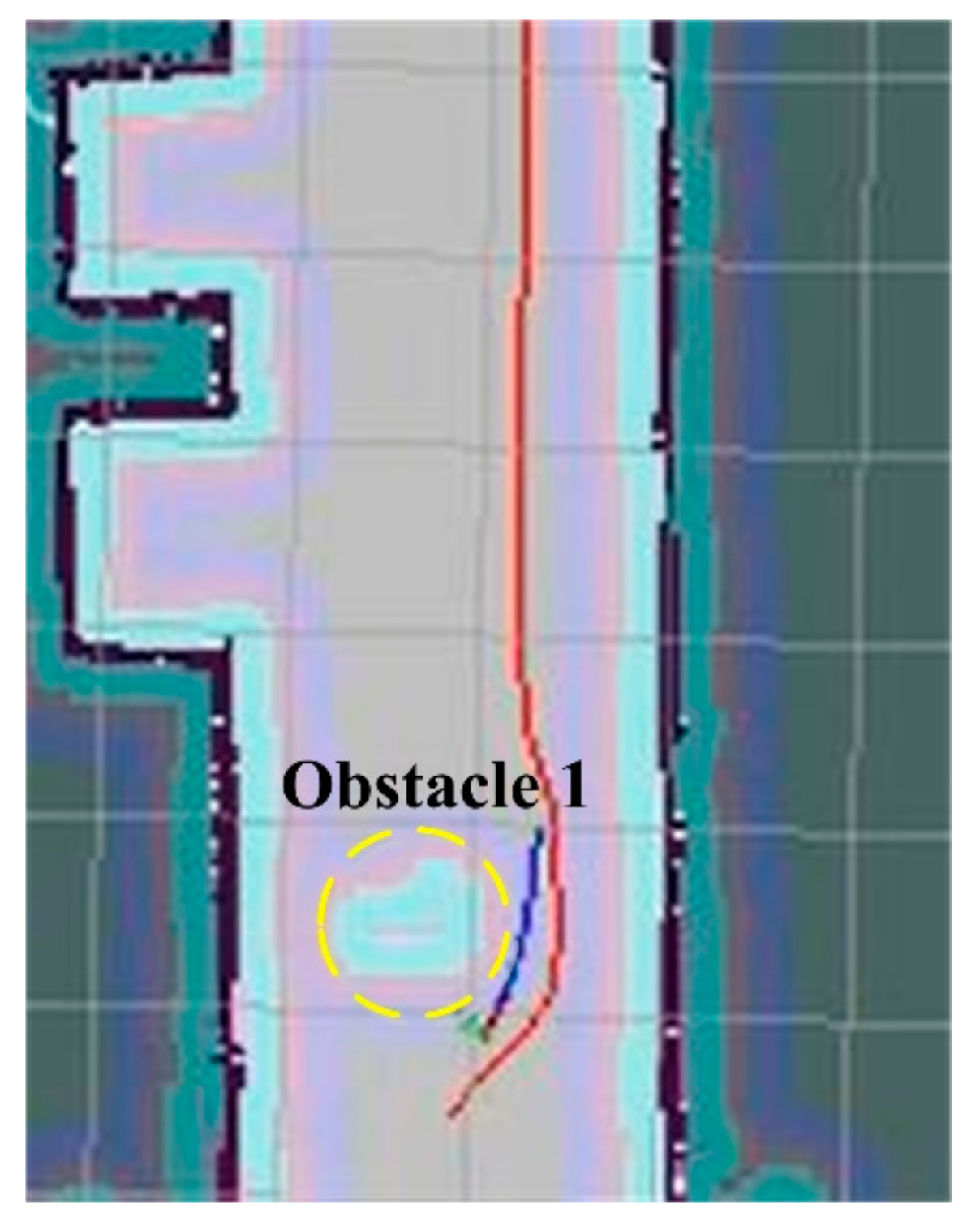
4.3.2. Navigation Test under Obstacle Environment
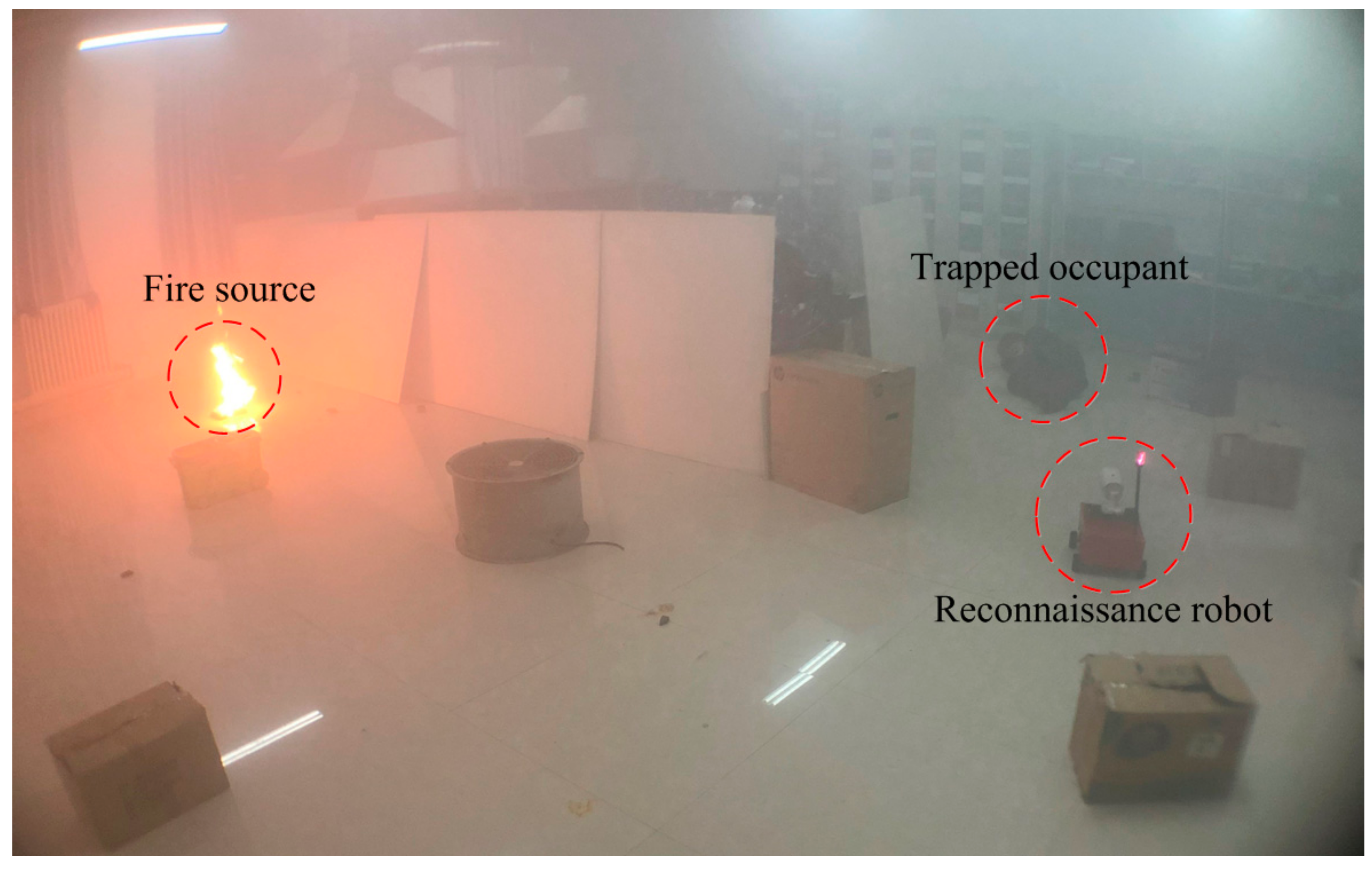
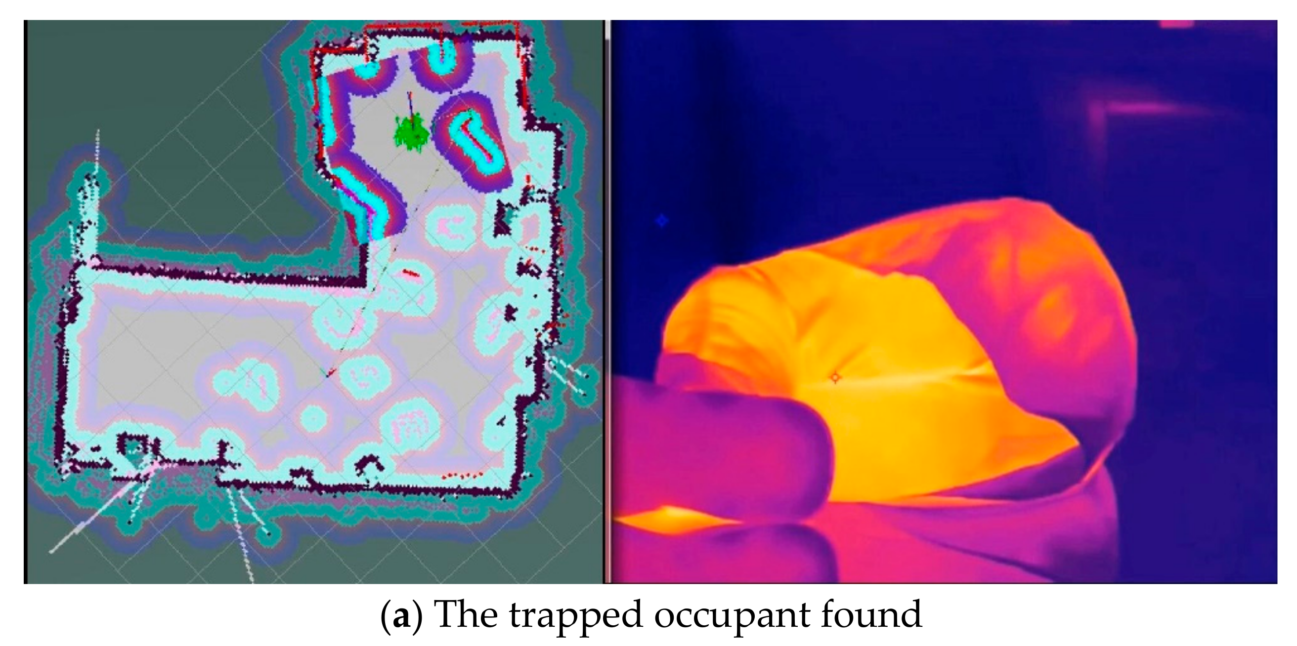
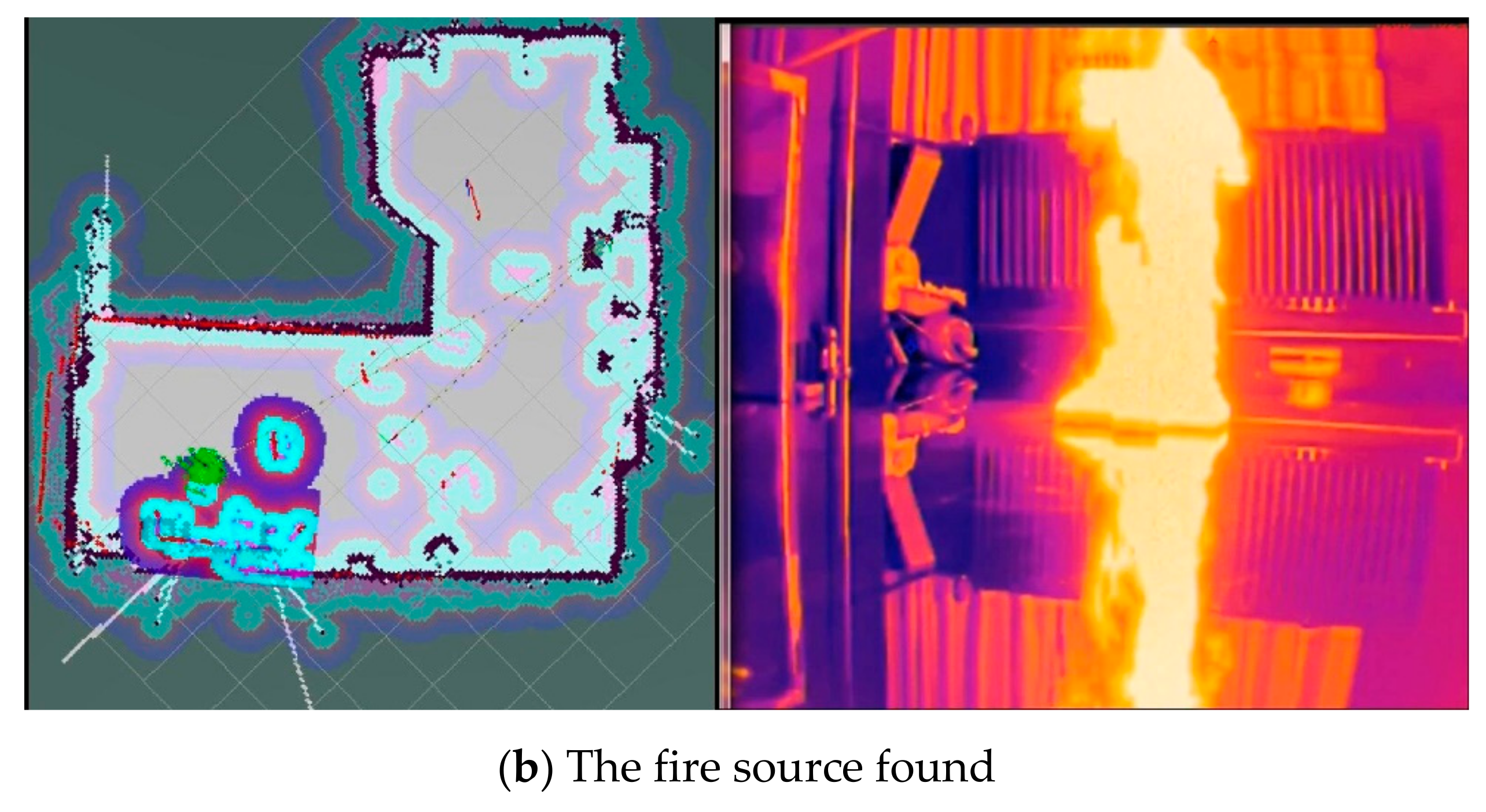
5. A Comprehensive Test under Fire Conditions
6. Conclusions
Author Contributions
Funding
Acknowledgments
Conflicts of Interest
References
- Hard, D.L.; Marsh, S.M.; Merinar, T.R.; Bowyer, M.E.; Miles, S.T.; Loflin, M.E.; Moore, P.H. Summary of recommendations from the National Institute for Occupational Safety and Health Fire Fighter Fatality Investigation and Prevention Program 2006–2014. J. Saf. Res. 2019, 68, 21–25. [Google Scholar] [CrossRef] [PubMed]
- Fahy, R.F.; LeBlanc, P.R.; Molis, J.L. Firefighter Fatalities in the United States–2016. National Fire Protection Association, July 2017, pp. 7–8. Available online: https://www.usfa.fema.gov/downloads/pdf/publications/ff_fat16.pdf (accessed on 18 November 2019).
- Fahy, R.F.; LeBlanc, P.R.; Molis, J.L. Firefighter fatalities in the United States-2011. Emmitsburg, MD: NFPA, July 2012, pp. 4–5. Available online: https://www.usfa.fema.gov/downloads/pdf/publications/ff_fat11.pdf (accessed on 18 November 2019).
- Karter, M.J. Fire loss in the United States during 2010. National Fire Protection Association Quincy, 1 September 2011; 42–44. [Google Scholar]
- Fan, X.; Xin, Z.; Li, J.; Li, Y.; Wan, J.; Sun, H.; Yang, Z.; Yu, M.; Yang, J.; Cheng, L. A Fire Protection Robot System Based on SLAM Localization and Fire Source Identification. In Proceedings of the 2019 IEEE 9th International Conference on Electronics Information and Emergency Communication (ICEIEC), Beijing, China, 12–14 July 2019; pp. 555–560. [Google Scholar]
- Li, S.; Feng, C.; Liang, X.; Qin, H. A guided vehicle under fire conditions based on a modified ultrasonic obstacle avoidance technology. Sensors 2018, 18, 4366. [Google Scholar] [CrossRef] [PubMed]
- Schneider, F.E.; Wildermuth, D. Using robots for firefighters and first responders: Scenario specification and exemplary system description. In Proceedings of the IEEE 2017 18th International Carpathian Control Conference (ICCC), Sinaia, Romania, 28–31 May 2017; pp. 216–221. [Google Scholar]
- Martinson, E.; Lawson, W.E.; Blisard, S.; Harrison, A.M.; Trafton, J.G. Fighting fires with human robot teams. In Proceedings of the 2012 IEEE/RSJ International Conference on Intelligent Robots and Systems, 7–12 October; pp. 2682–2683.
- Sucuoglu, H.S.; Bogrekci, I.; Demircioglu, P. Development of Mobile Robot with Sensor Fusion Fire Detection Unit. IFAC-Papers OnLine 2018, 51, 430–435. [Google Scholar] [CrossRef]
- Kim, J.H.; Starr, J.W.; Lattimer, B.Y. Firefighting robot stereo infrared vision and radar sensor fusion for imaging through smoke. Fire Technol. 2015, 51, 823–845. [Google Scholar] [CrossRef]
- Alhaza, T.; Alsadoon, A.; Alhusinan, Z.; Jarwali, M. New Concept for Indoor Fire Fighting Robot. Procedia–Social Behav. Sci. 2015, 195, 2343–2352. [Google Scholar] [CrossRef][Green Version]
- Shaffer, J.A.; Carrillo, E.; Xu, H. Hierarchal Application of Receding Horizon Synthesis and Dynamic Allocation for UAVs Fighting Fires. IEEE Access 2018, 6, 78868–78880. [Google Scholar] [CrossRef]
- Zhang, W.; Dai, C. Development of a new remote controlled emergency-handling and fire-fighting robot. In Proceedings of the IEEE 2009 WRI World Congress on Computer Science and Information Engineering, Los Angeles, CA, USA, 31 March–2 April 2009; Volume 7, pp. 239–243. [Google Scholar]
- Tan, C.F.; Liew, S.M.; Alkahari, M.R.; Ranjit, S.S.S.; Said, M.R.; Chen, W.; Rauterberg, G.W.M.; Sivakumar, D.; Sivarao. Firefighting mobile robot: state of the art and recent development. Aust. J. Basic Appl. Sci. 2013, 7, 220–223. [Google Scholar]
- Liu, P.; Yu, H.; Cang, S.; Vladareanu, L. Robot-assisted smart firefighting and interdisciplinary perspectives. In Proceedings of the 2016 22nd IEEE International Conference on Automation and Computing (ICAC), Colchester, UK, 7–8 September 2016; pp. 395–401. [Google Scholar]
- Kim, J.H.; Keller, B.; Lattimer B, Y. Sensor fusion based seek-and-find fire algorithm for intelligent firefighting robot. In Proceedings of the IEEE/ASME International Conference on Advanced Intelligent Mechatronics, Wollongong, NSW, Australia, 9–12 July 2013. [Google Scholar]
- Berrabah, S.A.; Baudoin, Y.; Sahli, H. SLAM for robotic assistance to fire-fighting services. In Proceedings of the 2010 IEEE 8th World Congress on Intelligent Control and Automation, Jinan, China, 7–9 July 2010; pp. 362–367. [Google Scholar]
- Jiang, H. Mobile Fire Evacuation System for Large Public Buildings Based on Artificial Intelligence and IoT. IEEE Access 2019, 7, 64101–64109. [Google Scholar] [CrossRef]
- Cabrero, S.; Paneda , X.G.; Melendi, D.; García, R.; Plagemann, T. Using Firefighter Mobility Traces to Understand Ad-Hoc Networks in Wildfires. IEEE Access 2017, 6, 1331–1341. [Google Scholar] [CrossRef]
- Xu, L.; He, J.; Wang, P.; Pahlavan, K.; Ning, H.; Wang, Q. Toward Emergency Indoor Localization: Maximum Correntropy Criterion Based Direction Estimation Algorithm for Mobile TOA Rotation Anchor. IEEE Access 2018, 6, 35867–35878. [Google Scholar] [CrossRef]
- Du, G.; Zhang, P.; Li, D. Human–manipulator interface based on multisensory process via Kalman filters. IEEE Trans. Ind. Electron. 2014, 61, 5411–5418. [Google Scholar]
- Du, G.; Zhang, P. A markerless human–robot interface using particle filter and Kalman filter for dual robots. IEEE Trans. Ind. Electron. 2014, 62, 2257–2264. [Google Scholar] [CrossRef]
- Du, G.; Zhang, P.; Liu, X. Markerless human–manipulator interface using leap motion with interval Kalman filter and improved particle filter. IEEE Trans. Ind. Inf. 2016, 12, 694–704. [Google Scholar] [CrossRef]
- Sun, Y.; Zhao, Y.; Schiller, J. An indoor positioning system based on inertial sensors in smartphone. In Proceedings of the 2015 IEEE Wireless Communications and Networking Conference (WCNC), New Orleans, LA, USA, 9–12 March 2015; pp. 2221–2226. [Google Scholar]
- Segura, M.; Mut, V.; Sisterna, C. Ultra wideband indoor navigation system. IET Radar Sonar Navig. 2012, 6, 402–411. [Google Scholar] [CrossRef]
- Zhou, Y.; Zheng, X.; Chen, R.; Xiong, H. Image-based localization aided indoor pedestrian trajectory estimation using smartphones. Sensors 2018, 18, 258. [Google Scholar] [CrossRef] [PubMed]
- Zhang, K.; Shen, C.; Zhou, Q.; Wang, H.; Gao, Q.; Chen, Y. A combined GPS UWB and MARG locationing algorithm for indoor and outdoor mixed scenario. Cluster Comput. 2018, 1–10. [Google Scholar]
- Yang, B.; Xu, X.; Zhang, T.; Li, Y.; Tong, J. An Indoor Navigation System Based on Stereo Camera and Inertial Sensors with Points and Lines. J. Sens. 2018. [Google Scholar]
- AL-Madani, B.; Orujov, F.; Maskeliūnas, R.; Damaševičius, R.; Venčkauskas, A. Fuzzy Logic Type-2 Based Wireless Indoor Localization System for Navigation of Visually Impaired People in Buildings. Sensors 2019, 19, 2114. [Google Scholar] [CrossRef] [PubMed]


| Technology | Positioning Accuracy | Measurement Principle | Require Base Station |
|---|---|---|---|
| UWB a | Cm–m | Time from objective reflection | Yes |
| WLAN b | m | Location fingerprinting | Yes |
| RFID c | Mm–dm | Similarity detection and location fingerprinting | Yes |
| ZigBee | m | Location fingerprinting | Yes |
| Bluetooth | Dm–m | Location fingerprinting | Yes |
| SLAM d | cm | Environmental feature extraction | No |
| Technical Parameter | Value | Maximum | Note |
|---|---|---|---|
| Measurement range | 0.15–12 m | - | Measured based on white object with high reflectivity |
| Measurement resolution | <0.5 mm | N.A. | The measured object is within 1.5 m |
| Scanning angle | 0–360° | N.A. | - |
| Angular resolution | 0.9° | 1.35° | Scanning frequency of 10 Hz |
| Technology | Size of the Tested Space | Positioning Accuracy (m) | References |
|---|---|---|---|
| PDR a | 9.7 m × 5.94 m | 1.96 | Sun et al. [24] |
| UWB b | 6 m × 8 m | 0.2 | Segura et al. [25] |
| Camera/ PDR | 16 m × 7.7 m | 0.56 | Zhou et al. [26] |
| GPS c/UWB/ MARG d | Business center | 3.2 | Zhang et al. [27] |
| Stereo Camera | 8 m × 8.4 m × 4 m | 0.677 | Yang et al. [28] |
| BLE e fingerprint, fuzzy logic | 52.5 m × 12.5 m | 0.43 | AL-Madani et al. [29] |
| SLAM f | 22.2 m × 2.7 m | 0.31 | This study |
| Navigation Point | Navigation Distance (m) | Distance Error (m) | Distance Error Percentage (%) | Angle Error |
|---|---|---|---|---|
| 1 | 12.0 | 0.26 | 2.17 | 4° |
| 2 | 27.3 | 0.82 | 3.00 | 0° |
| 3 | 36.2 | 1.26 | 3.48 | 10° |
| 4 | 43.3 | 1.27 | 2.93 | 5° |
© 2019 by the authors. Licensee MDPI, Basel, Switzerland. This article is an open access article distributed under the terms and conditions of the Creative Commons Attribution (CC BY) license (http://creativecommons.org/licenses/by/4.0/).
Share and Cite
Li, S.; Feng, C.; Niu, Y.; Shi, L.; Wu, Z.; Song, H. A Fire Reconnaissance Robot Based on SLAM Position, Thermal Imaging Technologies, and AR Display. Sensors 2019, 19, 5036. https://doi.org/10.3390/s19225036
Li S, Feng C, Niu Y, Shi L, Wu Z, Song H. A Fire Reconnaissance Robot Based on SLAM Position, Thermal Imaging Technologies, and AR Display. Sensors. 2019; 19(22):5036. https://doi.org/10.3390/s19225036
Chicago/Turabian StyleLi, Sen, Chunyong Feng, Yunchen Niu, Long Shi, Zeqi Wu, and Huaitao Song. 2019. "A Fire Reconnaissance Robot Based on SLAM Position, Thermal Imaging Technologies, and AR Display" Sensors 19, no. 22: 5036. https://doi.org/10.3390/s19225036
APA StyleLi, S., Feng, C., Niu, Y., Shi, L., Wu, Z., & Song, H. (2019). A Fire Reconnaissance Robot Based on SLAM Position, Thermal Imaging Technologies, and AR Display. Sensors, 19(22), 5036. https://doi.org/10.3390/s19225036