MIGOU: A Low-Power Experimental Platform with Programmable Logic Resources and Software-Defined Radio Capabilities


Abstract
1. Introduction
2. Related Work
3. MIGOU Platform
3.1. Design Criteria
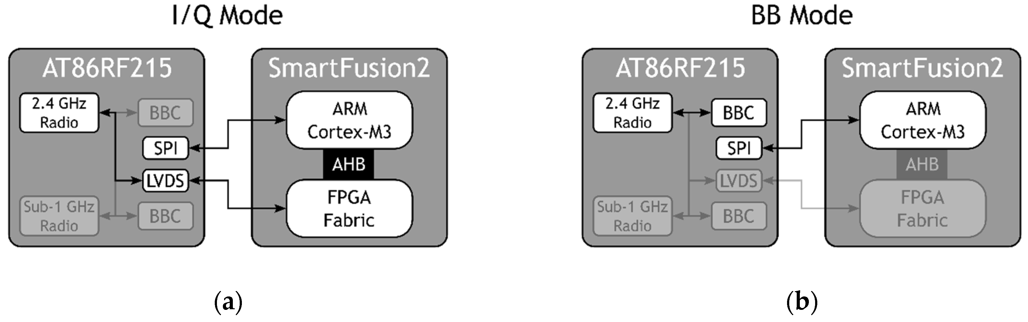
- Hybrid radio: The platform must be able to operate as a traditional node, using a highly integrated transceiver, and as an SDR system when a high radio flexibility is required for specific CR tasks. It should be noted that when no special task or customization is required, the use of an exclusively SDR system results in a considerable penalty in terms of power consumption, resource usage, and development time. This idea is further detailed in a previous work [31].
- Low-power programmable logic: The platform must include programmable logic resources where high-speed communication and/or processing tasks can be offloaded. This is especially important for applications with strict timing constraints, where it has been shown that these tasks can affect each other negatively [32]. Besides, these logical resources must support some low-power consumption mode for when they are not in use.
- Flexible hardware–software (HW–SW) boundary: The communication interface between the MCU, where the application runs, and the programmable logic must be as fast as possible to avoid bottlenecks, thus ensuring a flexible HW–SW boundary. This is an important feature for communication and processing tasks with precise timing requirements.
- Agile application development: Being an experimentation-oriented platform, the development of new applications should be as agile as possible. In this sense, the use of an OS is considered an essential aspect of the platform. In addition, it should have development and expansion interfaces that maximize its possibilities for use.
- Consumption measurement: The platform should integrate power consumption metering tools that allow the developer to evaluate the energy performance of the methods and algorithms being tested on it.
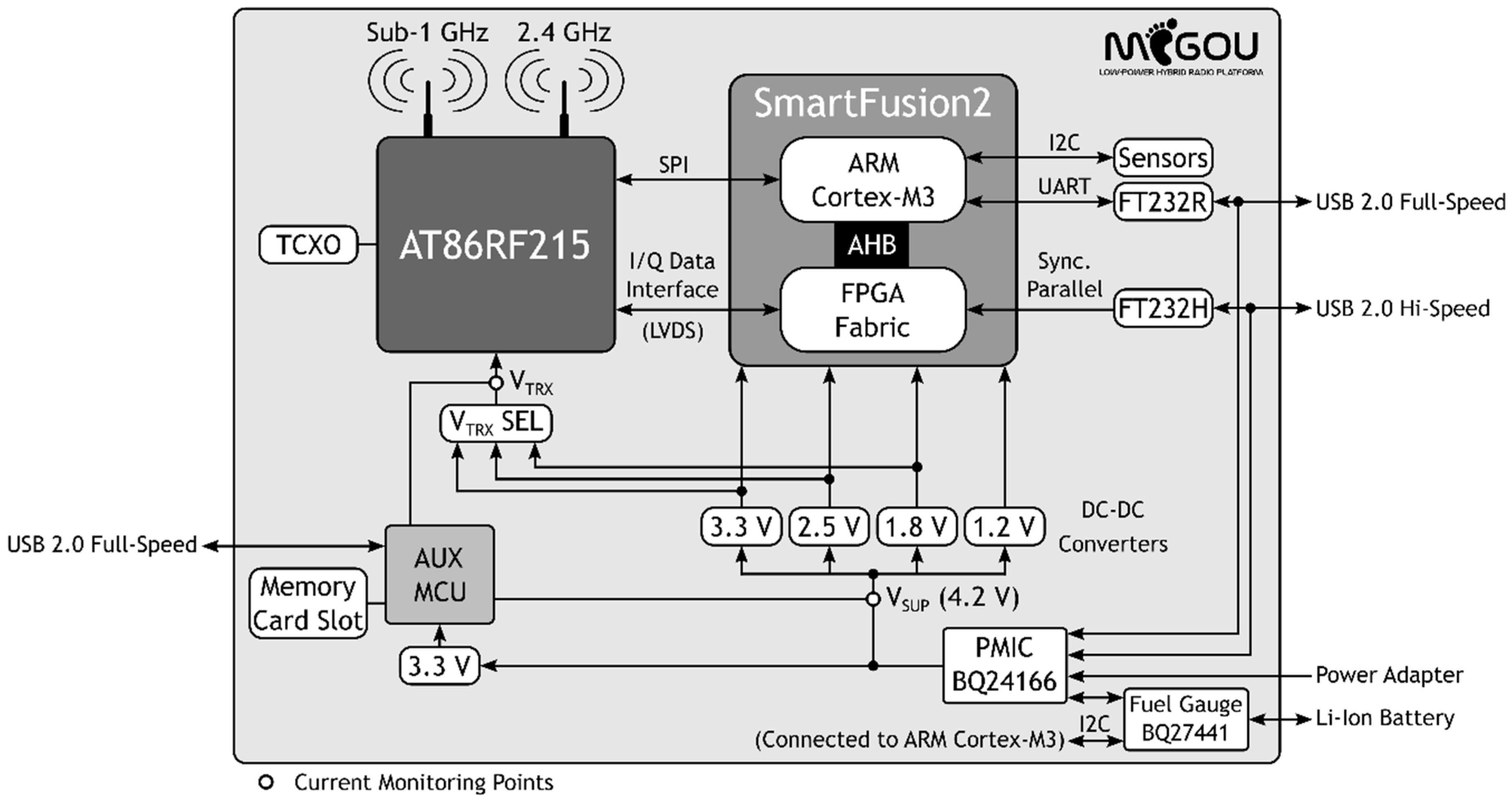
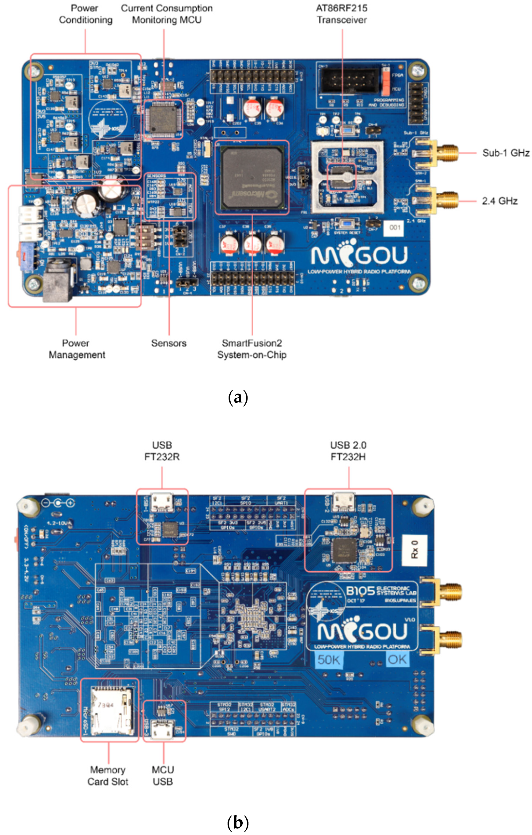
3.2. Design and Implementation
4. Materials and Methods
4.1. Materials
- YetiMote [16]: This platform was chosen as a representative traditional wireless sensor node. Its architecture is based on a STMicroelectronics STM32L476RE microcontroller and three COTS radio transceivers, two STMicroelectronics SPIRIT1 operating in the 433 MHz and 868 MHz bands, and a Texas Instruments CC2500 for the 2.4 GHz band.
- MarmotE SDR [29]: This platform was selected as a representative low-power SDR system, which was specifically designed to be battery-powered. In addition, amongst the two presented in Section 2, this is the one with more detailed power consumption data. As mentioned before, it is mainly based on a Maxim Integrated MAX2830 I/Q transceiver and a Microsemi SmartFusion SoC.
- B200mini and B210 USRPs [18]: Within the group that we consider high-performance SDR platforms, these two were chosen for having lower features and being widely used. The B200mini model is based on a Xilinx Spartan-6 XC6SLX75 FPGA and an Analog Devices AD9364 radio transceiver. On the other hand, the B210 model, which is more powerful, consists of a Xilinx Spartan-6 XC6SLX150 FPGA and an Analog Devices AD9361.
4.2. Methods
5. Results and Discussion
6. Conclusions
Supplementary Materials
Author Contributions
Funding
Conflicts of Interest
References
- Cisco Systems Inc. Cisco Visual Networking Index: Global Mobile Data Traffic Forecast Update, 2017-2022 White Paper; Cisco Systems Inc.: San Jose, CA, USA, 2019. [Google Scholar]
- Wunsch, F.; Paisana, F.; Rajendran, S.; Selim, A.; Alvarez, P.; Muller, S.; Koslowski, S.; Van den Bergh, B.; Pollin, S. DySPAN Spectrum Challenge: Situational Awareness and Opportunistic Spectrum Access Benchmarked. IEEE Trans. Cogn. Commun. Netw. 2017, 3, 550–562. [Google Scholar] [CrossRef]
- Joshi, G.P.; Nam, S.Y.; Kim, S.W. Cognitive Radio Wireless Sensor Networks: Applications, Challenges and Research Trends. Sensors 2013, 13, 11196–11228. [Google Scholar] [CrossRef] [PubMed]
- Shi, W.; Cao, J.; Zhang, Q.; Li, Y.; Xu, L. Edge Computing: Vision and Challenges. IEEE Internet Things J. 2016, 3, 637–646. [Google Scholar] [CrossRef]
- Ravì, D.; Wong, C.; Lo, B.; Yang, G. A Deep Learning Approach to on-Node Sensor Data Analytics for Mobile or Wearable Devices. IEEE J. Biomed. Heal. Inform. 2017, 21, 56–64. [Google Scholar] [CrossRef] [PubMed]
- Premsankar, G.; Di Francesco, M.; Taleb, T. Edge Computing for the Internet of Things: A Case Study. IEEE Internet Things J. 2018, 5, 1275–1284. [Google Scholar] [CrossRef]
- Chiang, M.; Zhang, T. Fog and IoT: An Overview of Research Opportunities. IEEE Internet Things J. 2016, 3, 854–864. [Google Scholar] [CrossRef]
- Szilvási, S. Advanced RF Techniques for Wireless Sensor Networks: The Software-Defined Radio Approach. Ph.D. Thesis, Institute for Software Integrated Systems (ISIS), Electrical Engineering, Vanderbilt University, Nashville, TN, USA, 2014. [Google Scholar]
- Dutta, P.; Kuo, Y.-S.; Lédeczi, A.; Schmid, T.; Völgyesi, P. Putting the Software Radio on a low-calorie diet. In Proceedings of the 9th ACM SIGCOMM Workshop on Hot Topics in Networks (HOTNETS), Monterey, CA, USA, 20–21 October 2010; pp. 1–6. [Google Scholar]
- Venieris, S.I.; Kouris, A.; Bouganis, C.-S. Toolflows for Mapping Convolutional Neural Networks on FPGAs: A Survey and Future Directions. ACM Comput. Surv. 2018, 51, 1–39. [Google Scholar] [CrossRef]
- Tang, Z.-L.; Li, S.-M.; Yu, L.-J. Implementation of Deep Learning-based Automatic Modulation Classifier on FPGA SDR Platform. Electronics 2018, 7, 122. [Google Scholar] [CrossRef]
- Zhou, A.; Santacruz, S.R.; Johnson, B.C.; Alexandrov, G.; Moin, A.; Burghardt, F.L.; Rabaey, J.M.; Carmena, J.M.; Muller, R. A wireless and artefact-free 128-channel neuromodulation device for closed-loop stimulation and recording in non-human primates. Nat. Biomed. Eng. 2019, 3, 15–26. [Google Scholar] [CrossRef] [PubMed]
- Xia, L.; Soltan, A.; Luo, J.; Chester, G.; Degenaar, P. A Flash-FPGA based Rodent Control System for Closed-loop Optogenetic Control of Epilepsy. In Proceedings of the IEEE International Symposium on Circuits and Systems, Florence, Italy, 27–30 May 2018; pp. 1–5. [Google Scholar]
- Polastre, J.; Szewczyk, R.; Culler, D. Telos: Enabling ultra-low power wireless research. In Proceedings of the 4th International Symposium on Information Processing in Sensor Networks (IPSN), Los Angeles, CA, USA, 15 April 2005; pp. 364–369. [Google Scholar]
- CrossBow MICAz Datasheet. Available online: http://www.openautomation.net/uploadsproductos/micaz_datasheet.pdf (accessed on 13 August 2019).
- Rodriguez-Zurrunero, R.; Utrilla, R.; Romero, E.; Araujo, A. An Adaptive Scheduler for Real-Time Operating Systems to Extend WSN Nodes Lifetime. Wirel. Commun. Mob. Comput. 2018, 2018, 1–10. [Google Scholar] [CrossRef]
- Rodriguez-Zurrunero, R.; Tirado-Andres, F.; Araujo, A. YetiOS: An adaptive operating system for wireless sensor networks. In Proceedings of the 43rd Annual IEEE Conference on Local Computer Networks Workshops (LCN Workshops), Chicago, IL, USA, 1–4 October 2018; pp. 16–22. [Google Scholar]
- Ettus Research. Available online: https://www.ettus.com/ (accessed on 13 August 2019).
- Blade RF x40. Available online: https://www.nuand.com/product/bladerf-x40/ (accessed on 13 August 2019).
- HackRF. Available online: https://greatscottgadgets.com/hackrf/ (accessed on 13 August 2019).
- WARP Project. Available online: https://warpproject.org/trac/wiki/about (accessed on 13 August 2019).
- ADALM-PLUTO. Available online: https://www.analog.com/en/design-center/evaluation-hardware-and-software/evaluation-boards-kits/adalm-pluto.html# (accessed on 13 August 2019).
- LimeSDR Boards. Available online: https://limemicro.com/products/boards/ (accessed on 13 August 2019).
- Rajendran, S.; Lenders, V.; Calvo-Palomino, R.; Cordobes, H.; Pollin, S.; Fuchs, M.; Giustiniano, D.; Van den Bergh, B. Electrosense: Open and Big Spectrum Data. IEEE Commun. Mag. 2017, 56, 210–217. [Google Scholar] [CrossRef]
- Narayanan, R.; Kumar, S. Revisiting Software Defined Radios in the IoT Era. In Proceedings of the 17th ACM Workshop on Hot Topics in Networks, Redmond, WA, USA, 15–16 November 2018; pp. 43–49. [Google Scholar]
- Tomar, V.S.; Bhatia, V. Low Cost and Power Software Defined Radio Using Raspberry Pi for Disaster Effected Regions. Procedia Comput. Sci. 2015, 58, 401–407. [Google Scholar] [CrossRef]
- RTL-SDR. Available online: https://www.rtl-sdr.com/ (accessed on 13 August 2019).
- GNU Radio. Available online: https://www.gnuradio.org/ (accessed on 13 August 2019).
- Szilvási, S.; Babják, B.; Völgyesi, P.; Lédeczi, Á. MarmotE SDR: Experimental platform for low-power wireless protocol stack research. J. Sens. Actuator Netw. 2013, 2, 631–652. [Google Scholar] [CrossRef]
- Kuo, Y.-S.; Pannuto, P.; Schmid, T.; Dutta, P. Reconfiguring the software radio to improve power, price, and portability. In Proceedings of the 10th ACM Conference on Embedded Network Sensor Systems (SenSys), Toronto, ON, Canada, 6–9 November 2012; pp. 267–280. [Google Scholar]
- Utrilla, R.; Rozas, A.; Blesa, J.; Araujo, A. A Hybrid Approach to Enhance Cognitive Wireless Sensor Networks with Energy-Efficient Software-Defined Radio Capabilities. In Proceedings of the 2017 International Conference on Embedded Wireless Systems and Networks, Uppsala, Sweden, 20–22 February 2017; pp. 294–299. [Google Scholar]
- Rodriguez-Zurrunero, R.; Utrilla, R.; Rozas, A.; Araujo, A. Process Management in IoT Operating Systems: Cross-Influence between Processing and Communication Tasks in End-Devices. Sensors 2019, 19, 805. [Google Scholar] [CrossRef] [PubMed]
- The FreeRTOSTM Kernel. Available online: https://www.freertos.org/ (accessed on 13 August 2019).
- Keysight B2902A Precision Source/Measure Unit. Available online: https://www.keysight.com/en/pd-1983585-pn-B2902A/precision-source-measure-unit-2-ch-100-fa-210-v-3-a-dc-105-a-pulse?cc=ES&lc=eng (accessed on 23 October 2019).
- Ruideng AT35 USB Tester. Available online: http://www.ruidengkeji.com/inst/AT35.pdf (accessed on 8 September 2019).


| Chip | Subsystem | I/Q Mode | BB Mode | Sleep |
|---|---|---|---|---|
| SmartFusion2 (M2S050) | FPGA | ON @ 50 MHz | Flash*Freeze | Flash*Freeze |
| MSS | ON @ 50 MHz | ON @ 50 MHz | WFI @ 1 MHz 1 | |
| AT86RF215 (VTRX = 1.8 V) | Sub-1 GHz Radio | OFF | OFF | OFF |
| Sub-1 GHz BBC | OFF | OFF | OFF | |
| 2.4 GHz Radio | ON | ON | OFF | |
| 2.4 GHz BBC | OFF | ON | OFF | |
| TCXO | - | ON | ON | OFF |
| Configuration Parameter | YetiMote | MarmotE SDR | B200mini and B200 USRPs | MIGOU BB Mode | MIGOU I/Q Mode |
|---|---|---|---|---|---|
| Active Clock | 48 MHz | 10 MHz | 32 MHz | 50 MHz | 50 MHz |
| Standby Clock | 32 kHz | 32 kHz | Unknown | 1 MHz | 1 MHz |
| Operating Band | 2.4 GHz | 2.4 GHz | 2.4 GHz | 2.4 GHz | 2.4 GHz |
| Modulation | GMSK | GMSK | GMSK | BFSK | GMSK |
| Data Rate | 250 kbps | 250 kbps | 250 kbps | 200 kbps | 250 kbps |
| Transmission Power | 0 dBm | 0 dBm | 0 dBm | 0 dBm | 0 dBm |
| Hardware Feature | YetiMote [16] | MarmotE SDR [29] | B200mini/B210 USRPs [18] | MIGOU |
|---|---|---|---|---|
| Processor | ARM Cortex-M4 Up to 80 MHz Floating Point Unit | ARM Cortex-M3 Up to 100 MHz | - | ARM Cortex-M3 Up to 142 MHz |
| Programmable Logic Elements | - | 6 k | 75 k/150 k | 56k |
| RF PHY Transceiver | SPIRIT1 (×2) CC2500 (×1) | - | - | AT86RF215 (×1) |
| Operating Freq. Range | 433 MHz, 868 MHz and 2.4 GHz bands | 2.4 GHz band | 70 MHz to 6 GHz | 433 MHz, 868 MHz and 2.4 GHz bands |
| Access to I/Q Signals—Max. Sample Rate | - | 22 MSps | 61.44 MSps | 4 MSps |
| MIGOU Mode | Operation Mode | Power Consumption (mW) | ||
|---|---|---|---|---|
| Average | Maximum | Minimum | ||
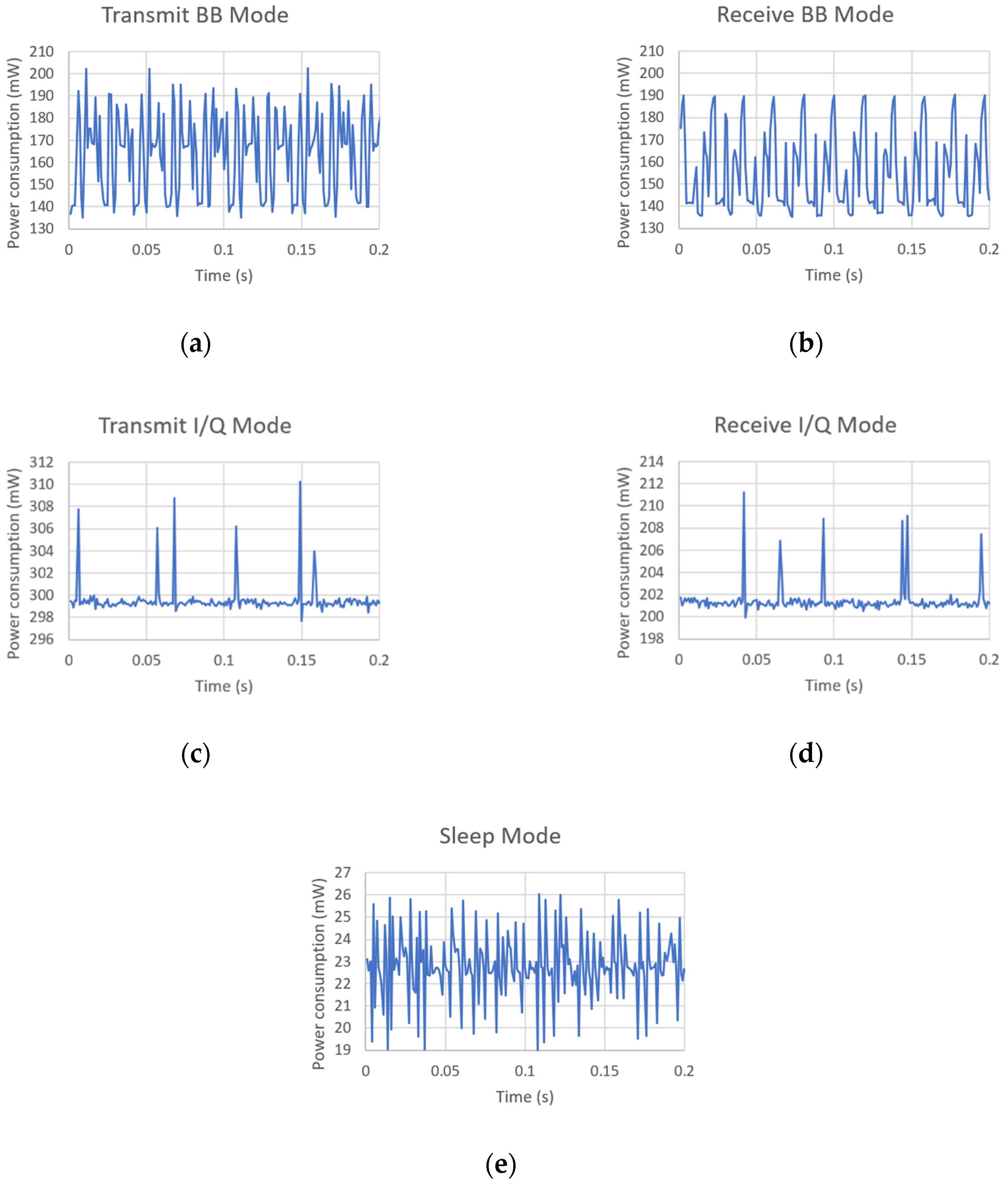
| BB | Transmit | 163.4 | 203.0 | 135.2 |
| BB | Receive | 154.5 | 190.4 | 133.5 |
| I/Q | Transmit | 299.6 | 324.4 | 296.7 |
| I/Q | Receive | 201.4 | 212.7 | 198.5 |
| - | Sleep | 22.8 | 26.8 | 18.8 |
© 2019 by the authors. Licensee MDPI, Basel, Switzerland. This article is an open access article distributed under the terms and conditions of the Creative Commons Attribution (CC BY) license (http://creativecommons.org/licenses/by/4.0/).
Share and Cite
Utrilla, R.; Rodriguez-Zurrunero, R.; Martin, J.; Rozas, A.; Araujo, A. MIGOU: A Low-Power Experimental Platform with Programmable Logic Resources and Software-Defined Radio Capabilities. Sensors 2019, 19, 4983. https://doi.org/10.3390/s19224983
Utrilla R, Rodriguez-Zurrunero R, Martin J, Rozas A, Araujo A. MIGOU: A Low-Power Experimental Platform with Programmable Logic Resources and Software-Defined Radio Capabilities. Sensors. 2019; 19(22):4983. https://doi.org/10.3390/s19224983
Chicago/Turabian StyleUtrilla, Ramiro, Roberto Rodriguez-Zurrunero, Jose Martin, Alba Rozas, and Alvaro Araujo. 2019. "MIGOU: A Low-Power Experimental Platform with Programmable Logic Resources and Software-Defined Radio Capabilities" Sensors 19, no. 22: 4983. https://doi.org/10.3390/s19224983
APA StyleUtrilla, R., Rodriguez-Zurrunero, R., Martin, J., Rozas, A., & Araujo, A. (2019). MIGOU: A Low-Power Experimental Platform with Programmable Logic Resources and Software-Defined Radio Capabilities. Sensors, 19(22), 4983. https://doi.org/10.3390/s19224983