Flexible UHF RFID Tag for Blood Tubes Monitoring

 ,
,  , , and
Abstract
:1. Introduction
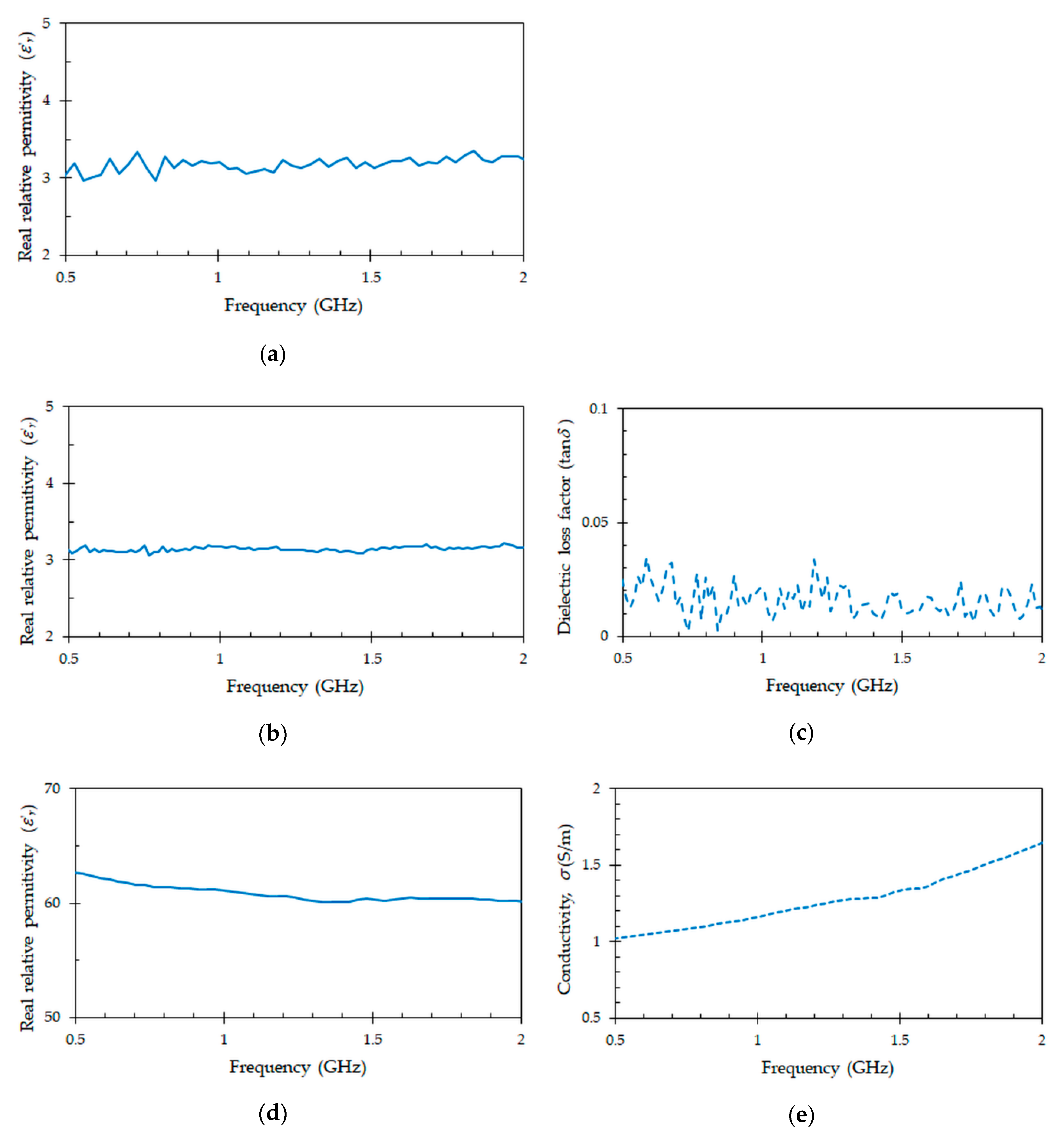
2. Electromagnetic Characterization of the Materials Involved in the Design of the Tag Antenna
3. Design of the Tag Antenna
3.1. Design Considerations
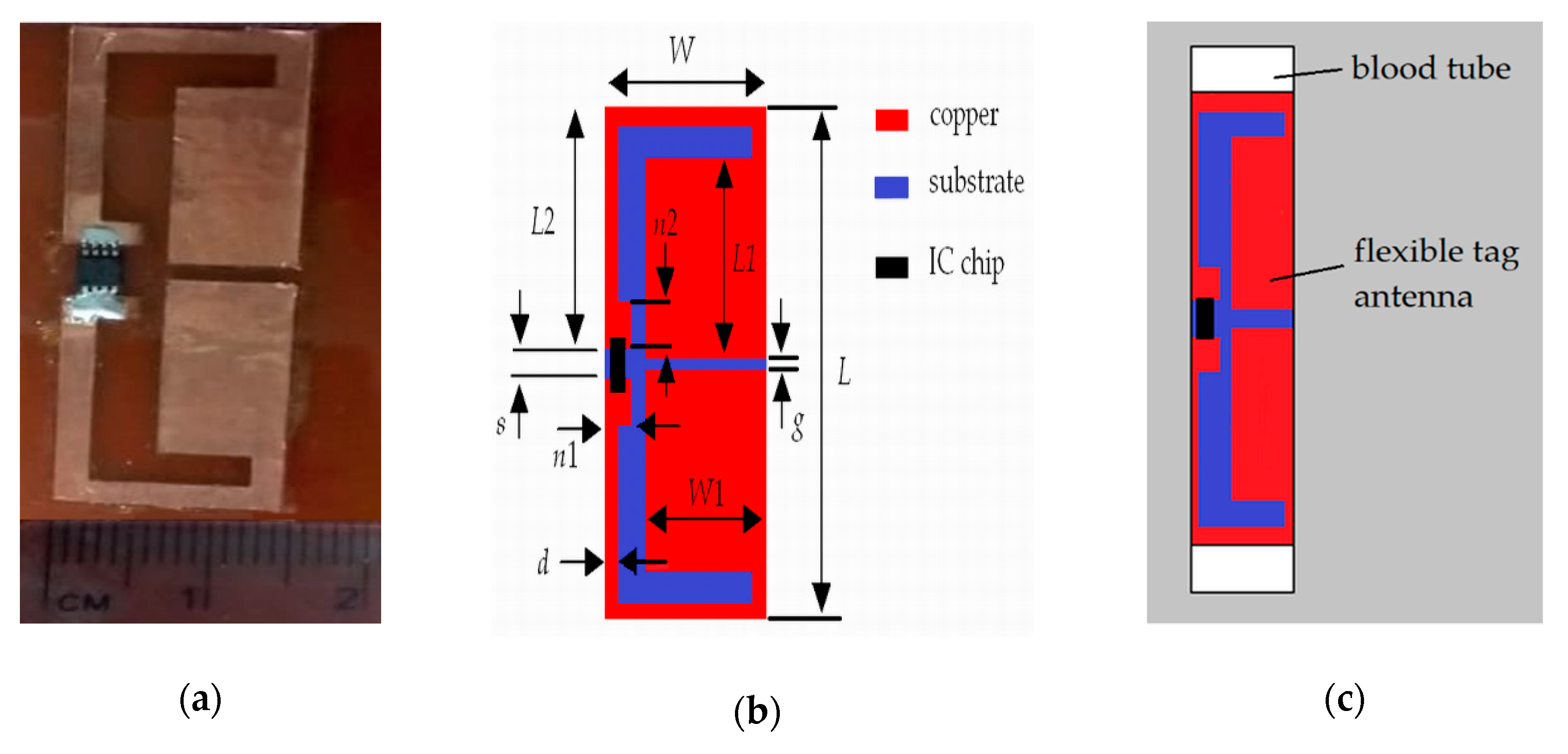
3.2. Structure of the Tag Antenna
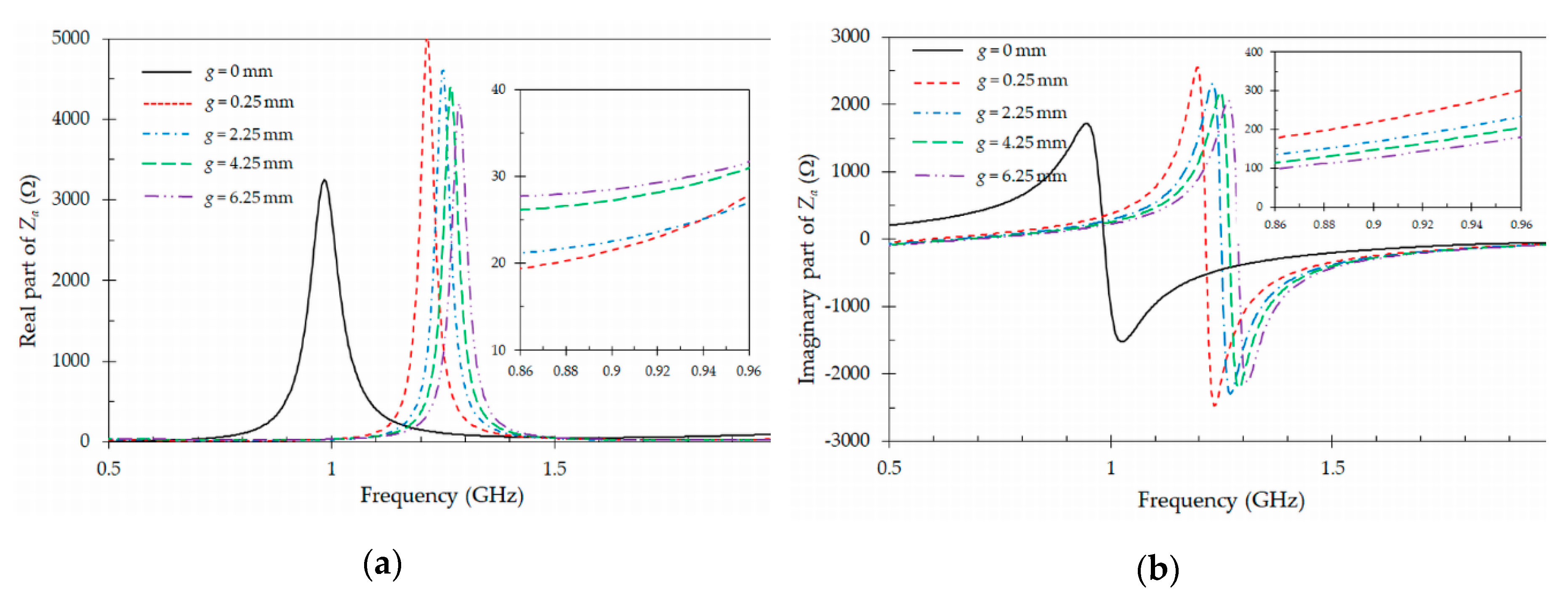
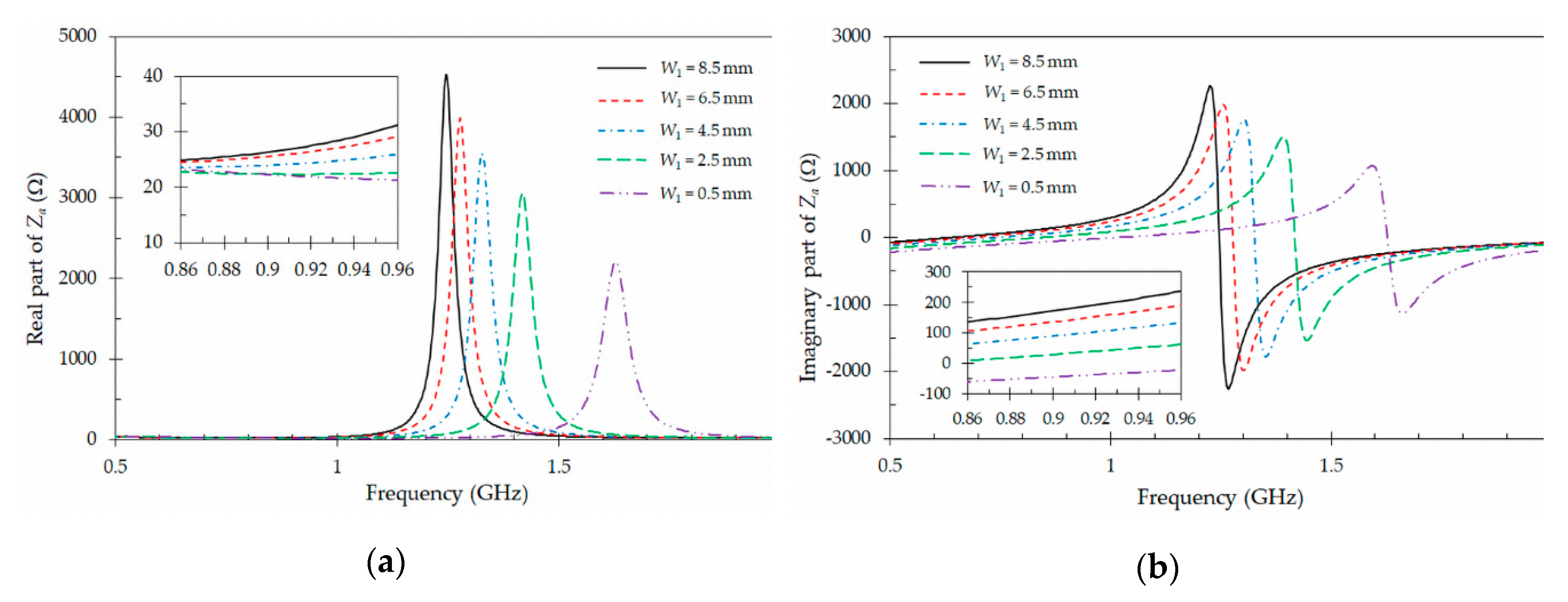
3.3. Optimization
3.4. Simulation Results
4. Fabrication and Experimental Characterization of the Proposed Tag Antenna
4.1. Fabrication
4.2. Impedance Measurement
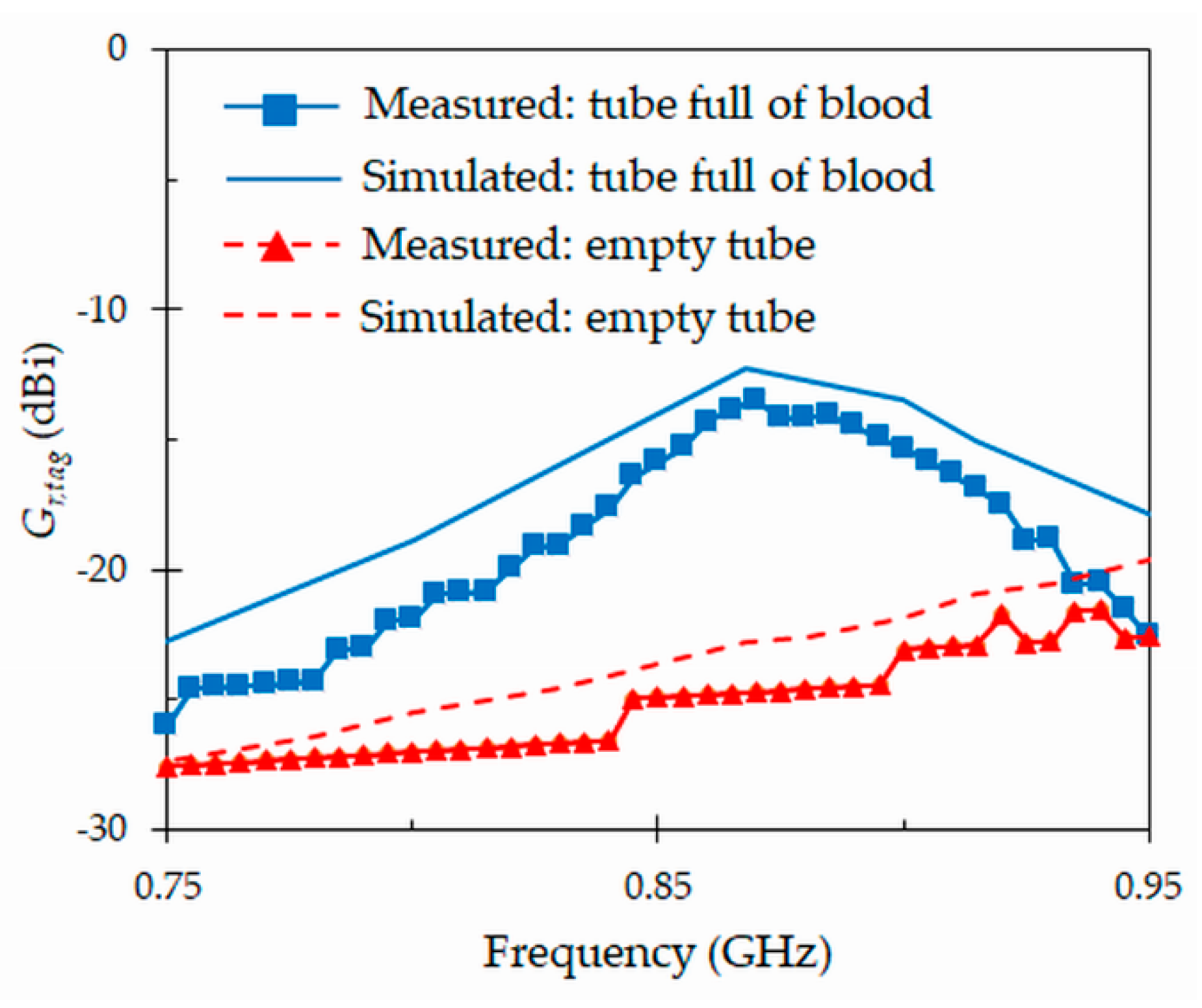
4.3. Realized Gain
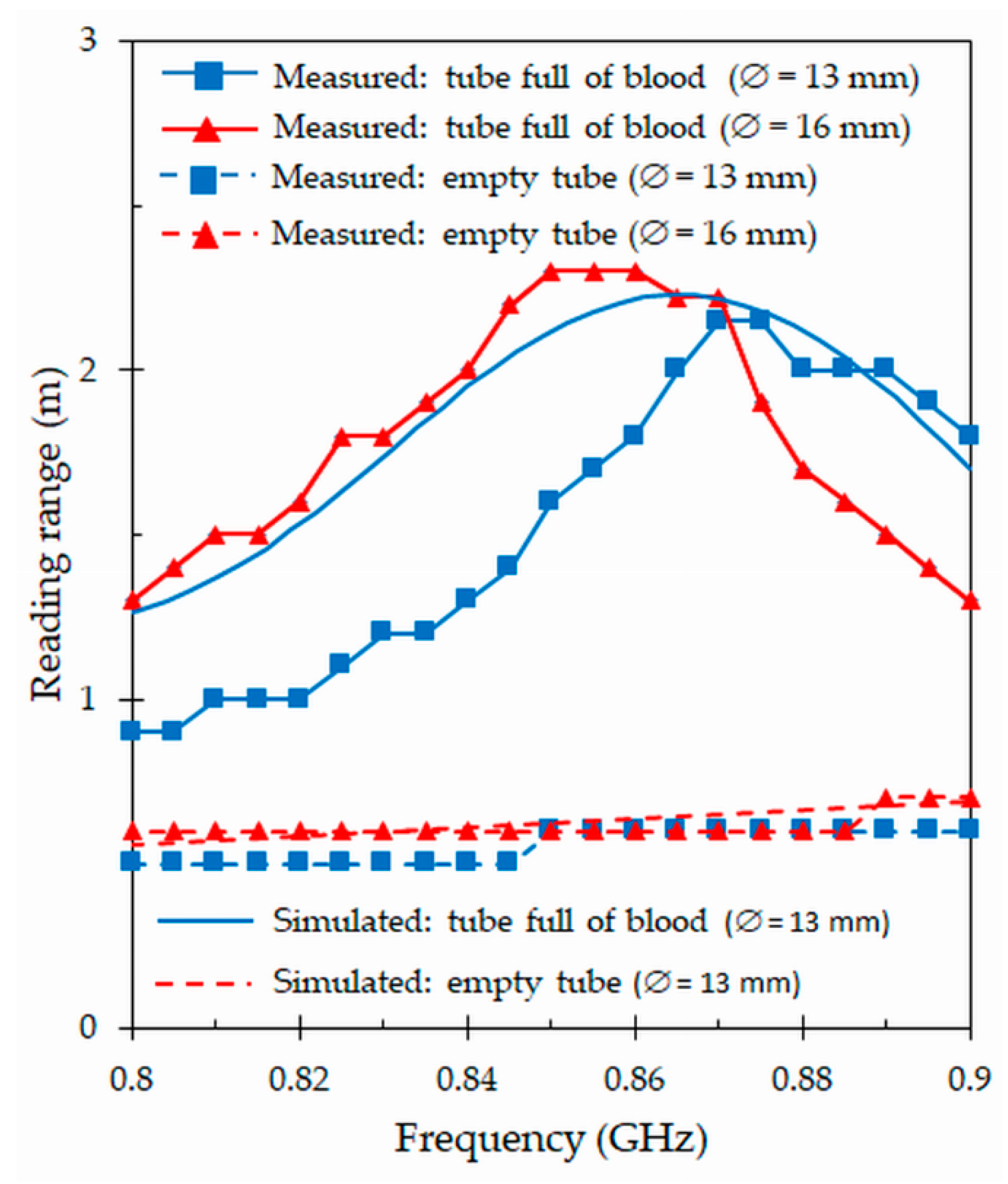
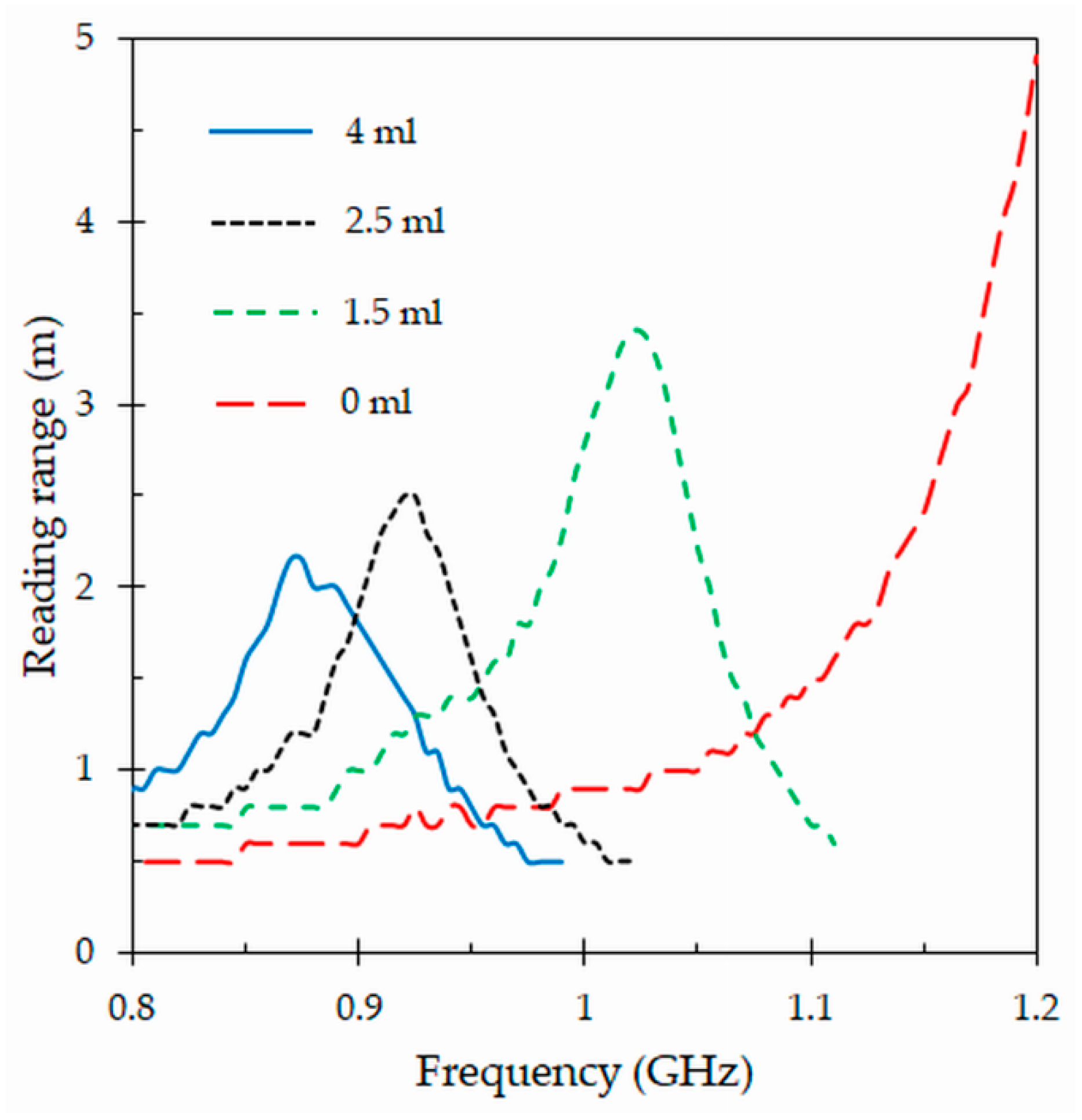
4.4. Reading Range
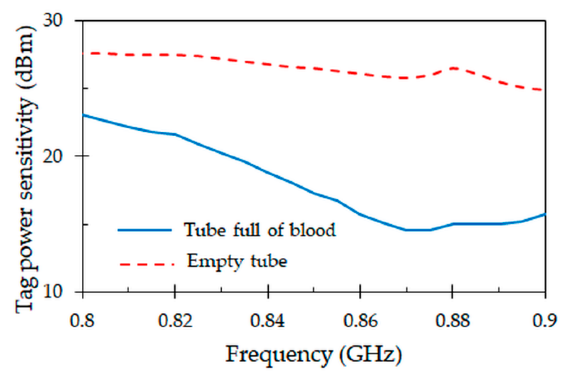
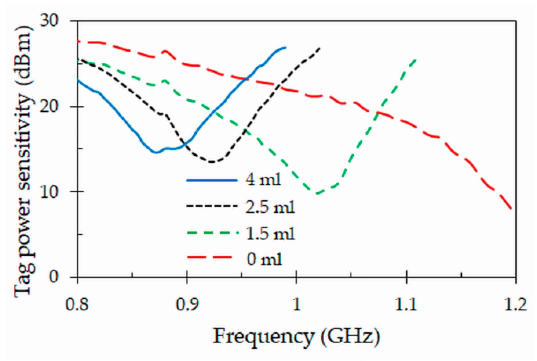
4.5. Tag Power Sensitivity
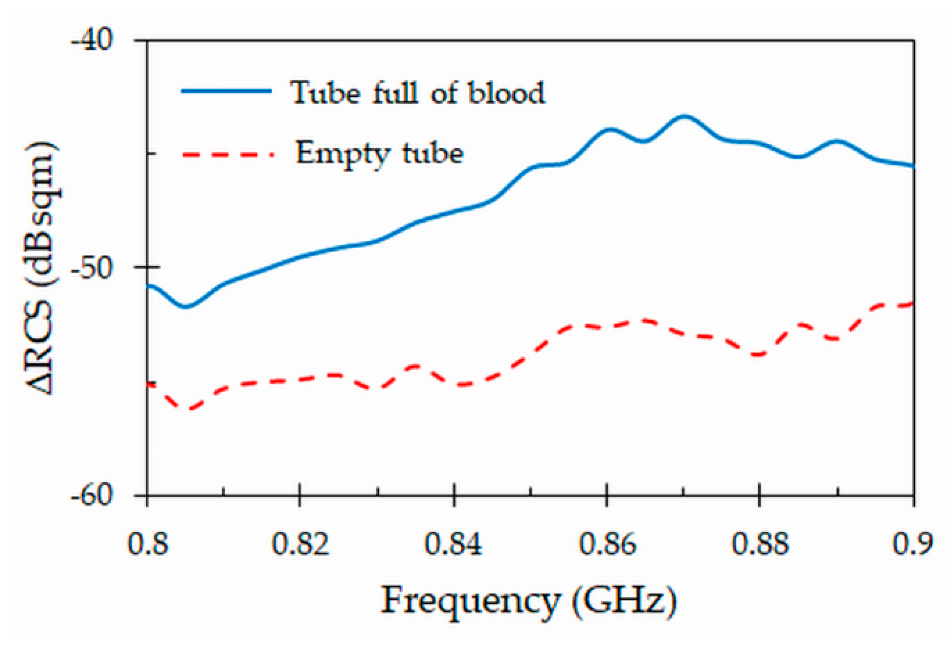
4.6. Differential Radar Cross Section
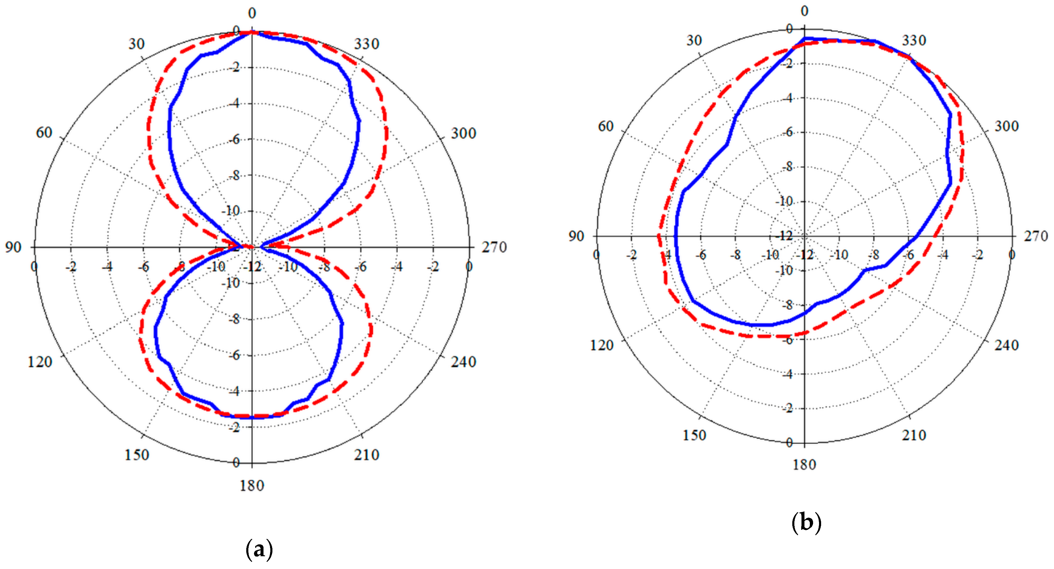
4.7. Radiation Patterns
4.8. Comparison with Other Designs
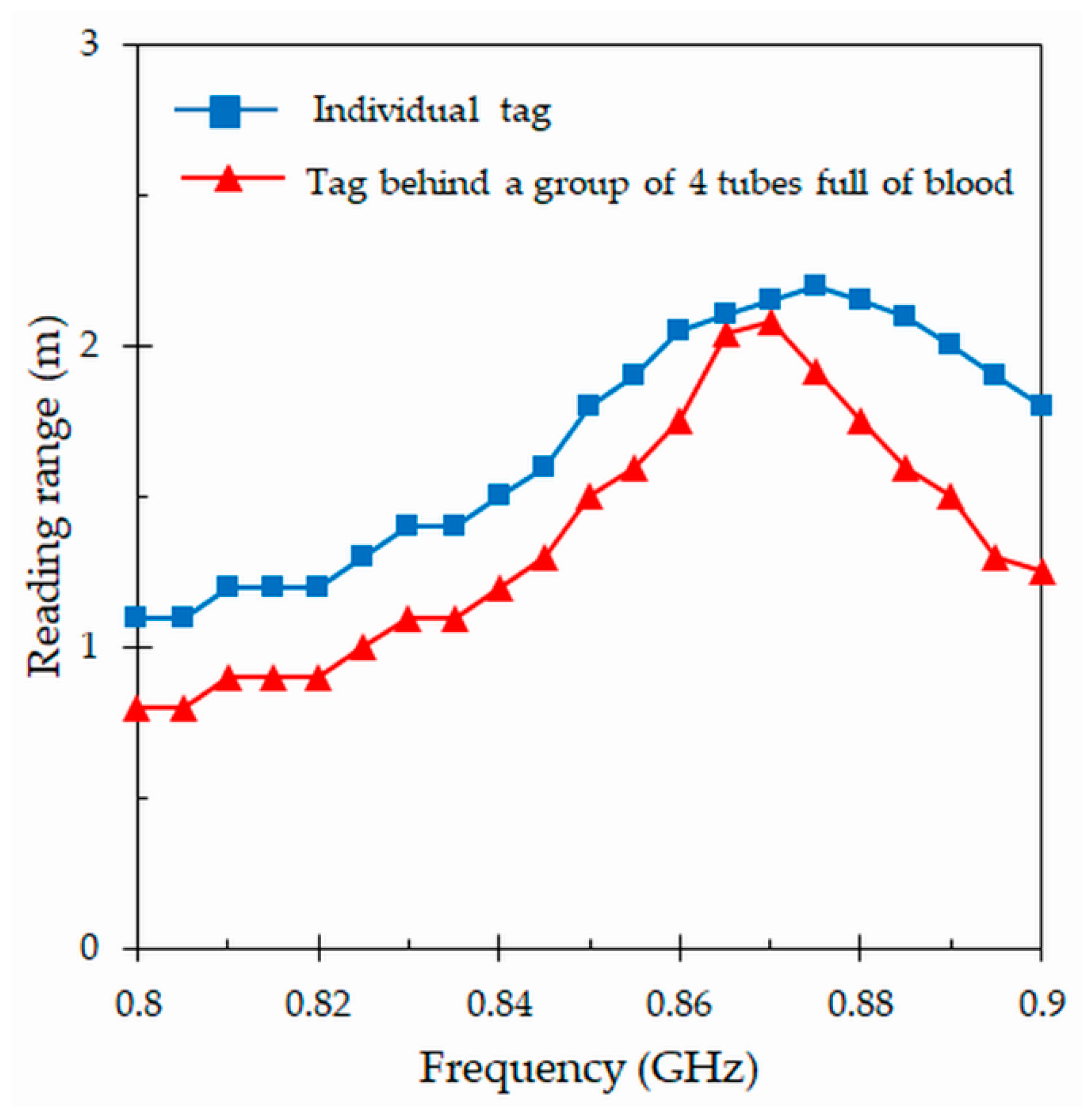
5. Application of the Proposed Tag as Volume Sensor
6. Conclusions
Author Contributions
Funding
Conflicts of Interest
References
- Finkenzeller, K. RFID Handbook: Fundamentals and Applications in Contacless Smart Cards, Radio Frequency Identification and Near-Field Communication, 3rd ed.; John Wiley & Sons: Hoboken, NJ, USA, 2010. [Google Scholar]
- Rao, K.V.S.; Nikitin, V.; Lam, S.F. Antenna design for UHF RFID tags: A review and a practical application. IEEE Trans. Antennas Propag. 2005, 53, 3870–3876. [Google Scholar] [CrossRef]
- Zhu, X.; Mukhopadhyay, S.K.; Kurata, H. A review of RFID technology and its managerial applications in different industries. J. Eng. Technol. Manag. 2012, 29, 152–167. [Google Scholar] [CrossRef]
- Zhang, J.; Tian, G.Y.; Marindra, A.M.; Sunny, A.I.; Zhao, A.B. A review of passive RFID tag antenna-based sensors and systems for structural health monitoring applications. Sensors 2017, 17, 265. [Google Scholar] [CrossRef] [PubMed]
- Hohberger, C.; Davis, R.; Briggs, L.; Gutierrez, A.; Veeramani, D. Applying radio-frequency identification (RFID) technology in transfusion medicine. Biologicals 2012, 40, 209–213. [Google Scholar] [CrossRef]
- Álvarez López, Y.; Franssen, J.; Álvarez Narciandi, G.; Pagnozzi, J.; González-Pinto Arrillaga, I.; Las-Heras Andrés, F. RFID Technology for management and tracking: E-health applications. Sensors 2018, 18, 2663. [Google Scholar] [CrossRef]
- Curty, J.P.; Declercq, M.; Dehollain, C.; Joehl, N. Design and Optimization of Passive UHF RFID Systems; Springer: New York, NY, USA, 2007. [Google Scholar]
- Balanis, C.A. Antenna Theory: Analysis and Design, 4th ed.; John Wiley & Sons: Hoboken, NJ, USA, 2016. [Google Scholar]
- Deleruyelle, T.; Pannier, P.; Egels, M.; Bergeret, E. An RFID tag antenna tolerant to mounting on materials. IEEE Antennas Propag. Mag. 2010, 52, 14–19. [Google Scholar] [CrossRef]
- Li, H.; Zhu, J.; Yu, Y. Compact single-layer RFID antenna tolerant to background materials. IEEE Access 2017, 5, 21070–21079. [Google Scholar] [CrossRef]
- Lozano, M.; Cid, J. DEHP plasticizer and blood bags: Challenges ahead. ISBT Sci. Ser. 2013, 8, 127–130. [Google Scholar] [CrossRef]
- Kratz, A.; Stanganelli, N.; Van Cott, E.M. A comparison of glass and plastic collection tubes for routine and specialized coagulation assays: A comprehensive study. Arch. Pathol. Lab. Med. 2006, 130, 39–44. [Google Scholar]
- Islam, M.T.; Alam, T.; Yahya, I.; Cho, M. Flexible radio-frequency identification (RFID) tag antenna for sensor applications. Sensors 2018, 18, 4212. [Google Scholar] [CrossRef]
- Rankl, W.; Effing, W. Smart Card Handbook, 4th ed.; John Wiley & Sons: New York, NY, USA, 2010. [Google Scholar]
- Marroco, G. The art of UHF RFID antenna design: Impedance-matching and size-reduction techniques. IEEE Antennas Propag. Mag. 2008, 50, 66–79. [Google Scholar] [CrossRef]
- Ibrahim, G.T.; Dutko, M.J. Tracking blood units in medical centers using passive UHF RFID systems. In Proceedings of the 122nd American Society for Engineering Education (ASEE) Annual Conference & Exposition, Seattle, WA, USA, 14–17 June 2015; p. 26. [Google Scholar]
- Björnimen, T.; Sydänheimo, L.; Ukkonen, L.; Rahmat-Samii, Y. Advances in antenna designs for UHF RFID tags mountable on conductive items. IEEE Antennas Propag. Mag. 2014, 56, 79–103. [Google Scholar] [CrossRef]
- Zaric, A.; Cruz, C.C.; de Matos, A.; da Silva, M.; Costa, J.R.; Fernandes, C.A. RFID-based Smart blood stock system. IEEE Antennas Propag. Mag. 2015, 57, 54–65. [Google Scholar] [CrossRef]
- Lin, Y.F.; Liao, C.T.; Chen, H.M.; Jiang, Z.D. Compact folded square-loop antenna for reading near-field RFID tags in blood sample tracking system. Electron. Lett. 2017, 53, 1627–1628. [Google Scholar] [CrossRef]
- Jeong, M.G.; Lee, W.S. A smart blood bag management system using a load-integrated U-shaped near-field RFID antenna array. IEEE Trans. Antennas Propag. 2019, 67, 1837–1843. [Google Scholar] [CrossRef]
- Fanti, A.; Secci, R.; Boi, G.; Casu, S.; Casula, G.A.; Mazzarella, G.; Montisci, G. A polycarbonate RFID tag for blood chain tracking. In Proceedings of the IEEE International Symposium on Antennas and Propagation (APS) & USNC/URSI National Radio Science Meeting, Vancouver, BC, Canada, 19–24 July 2015; pp. 356–357. [Google Scholar]
- Choi, J.; Jeon, B.; Chung, Y.; Yeo, J. Design of a UHF RFID tag antenna for RFID-based blood-bag management system. In Proceedings of the International Symposium on Antennas and Propagation (ISAP), Jeju, Korea, 25–28 October 2011. [Google Scholar]
- Björnimen, T.; Elsherbeni, A.Z.; Ukkonen, L. Low-profile conformal UHF RFID antenna for integration with water bottles. IEEE Antennas Wirel. Propag. Lett. 2011, 10, 1147–1150. [Google Scholar] [CrossRef]
- Sohrab, A.P.; Huang, Y.; Hussein, M.; Kod, M.; Carter, P. A UHF RFID tag with improved performance on liquid bottles. IEEE Antennas Wirel. Propag. Lett. 2016, 15, 1673–1676. [Google Scholar] [CrossRef]
- Makarovaite, V.; Hillier, A.J.R.; Holder, S.J.; Gourlay, C.W.; Batchelor, J.C. Passive wireless UHF RFID antenna label for sensing dielectric properties of aqueous and organic liquids. IEEE Sens. J. 2019, 19, 4299–4307. [Google Scholar] [CrossRef]
- Dupont Kapton FN. Available online: https://www.dupont.com/content/dam/Dupont2.0/Products/Electronics-and-imaging/Literature/DEC-Kapton-FN-datasheet.pdf (accessed on 3 July 2019).
- Ghodgaonkar, D.K.; Varadan, V.V.; Varadan, V.K. Free-space measurement of complex permittivity and complex permeability of magnetic materials at microwave frequencies. IEEE Trans. Instrum. Meas. 1990, 39, 387–394. [Google Scholar] [CrossRef]
- Hinojosa, J.; Faucon, L.; Queffelec, P.; Huret, F. S-parameter broadband measurements of microstrip lines and extraction of the substrate intrinsic properties. Microw. Opt. Tecnol. Lett. 2001, 30, 65–69. [Google Scholar] [CrossRef]
- Mehrota, P.; Chaterjee, B.; Sen, S. EM-wave biosensors: A review of RF, microwave, mm-wave and optical sensing. Sensors 2019, 19, 1013. [Google Scholar] [CrossRef] [PubMed]
- Chen, L.F.; Ong, C.K.; Varadan, V.V.; Varadan, V.K. Microwave Electronics: Measurement and Materials Characterization; John Wiley & Sons: Chichester, WS, UK, 2004. [Google Scholar]
- You, K.Y.; Mun, H.K.; Salleh, J.; Abbas, Z. A small and slim coaxial probe for single rice grain moisture sensing. Sensors 2013, 13, 2652–3663. [Google Scholar] [CrossRef] [PubMed]
- López-Rodríguez, P.; Escot-Bocanegra, D.; Poyatos-Martínez, D.; Weinmann, F. Comparison of metal-backed free-space and open-ended coaxial probe techniques for the dielectric characterization of aeronautical composites. Sensors 2016, 16, 967. [Google Scholar] [CrossRef] [PubMed]
- Stuchly, M.A.; Stuchly, S. Coaxial line reflection methods for measuring dielectric properties of biological substances at radio and microwave frequencies—A review. IEEE Trans. Instrum. Meas. 1980, 29, 176–183. [Google Scholar] [CrossRef]
- La Giaoia, A.; Porter, E.; Merunka, I.; Shahzad, A.; Salahuddin, S.; Jones, M.; O’Halloran, M. Open-ended coaxial probe technique for dielectric measurement of biological tissues: Challenges and common practices. Diagnostics 2018, 8, 40. [Google Scholar] [CrossRef]
- Martínez, F.L.; Hinojosa, J.; Doménech, G.; Fernández-Luque, F.J.; Zapata, J.; Ruiz, R.; Pardo, L. Dielectric constant tunability at microwave frequencies and pyroelectric behavior of lead-free submicrometer-structured (bi0.5Na0.5)1-xBaxTiO3 ferroelectric ceramics. IEEE Trans. Ultrason. Ferroelectr. Freq. Control 2013, 60, 1595–1602. [Google Scholar] [CrossRef]
- Konieczna, M.; Markiewicz, E.; Jurga, J. Dielectric properties of polyethylene terephthalate/polyphenylene sulfide/barium titanate nanocomposite for application in electronic industry. Polym. Eng. Sci. 2010, 50, 1613–1619. [Google Scholar] [CrossRef]
- Salahuddin, S.; Farrugia, L.; Sammut, C.V.; O’Halloran, M.; Porter, E. Dielectric properties of fresh human blood. In Proceedings of the International Conference on Electromagnetics in Advances Applications (ICEEAA), Verona, Italy, 11–15 September 2017; pp. 356–359. [Google Scholar]
- Qing, X.; Goh, C.K.; Chen, Z.N. Impedance characterization of RFID tag antennas and application in tag co-design. IEEE Trans. Microw. Theory Techn. 2009, 57, 1268–1274. [Google Scholar] [CrossRef]
- Abdulhadi, A.E.; Abhari, R. Design and experimental evaluation of miniaturized monopole UHF RFID tag antennas. IEEE Antennas Wirel. Propag. Lett. 2012, 11, 248–251. [Google Scholar] [CrossRef]
- Domenech-Asensi, G.; Hinojosa, J.; Martínez-Alajaríin, J.; Garrigos-Guerrero, J. Empirical model generation techniques for planar microwave components using electromagnetic linear regression models. IEEE Trans. Microw. Theory Techn. 2005, 11, 3305–3311. [Google Scholar] [CrossRef]
- Rahouyi, E.B.; Hinojosa, J.; Garrigós, J. Neuro-fuzzy modeling techniques for microwave components. IEEE Microw. Wirel. Comp. Lett. 2006, 16, 72–74. [Google Scholar] [CrossRef]
- Panescu, D.; Webster, J.G. Effects of changes in electrical and thermal conductivities on radiofrequency lesion dimensions. In Proceedings of the 19th Annual Conference of the IEEE Engineering in Medicine and Biology Society, Chicago, IL, USA, 30 October–2 November 1997; pp. 154–156. [Google Scholar]
- Otin, R. Numerical study of the thermal effects induced by a RFID antenna in vials of blood plasma. Prog. Electromagn. Res. Lett. 2011, 22, 129–138. [Google Scholar] [CrossRef]
- Fanti, A.; Casu, S.; Mazzarella, G. A numerical estimation of a RFID reader field and SAR inside a blood bag at UHF. Electronics 2016, 5, 77. [Google Scholar] [CrossRef]


| Parameter | Value (mm) | Parameter | Value (mm) |
|---|---|---|---|
| L | 49.5 | s | 5 |
| W | 15 | g | 2.25 |
| L1 | 18.75 | n1 | 5 |
| W1 | 8.5 | n2 | 3.5 |
| L2 | 18.25 | d | 2 |
| Reference | Tube/Bag/Liquid | Flexible (Yes/Not) | Antenna Type | Max. Reading Range (m) | 2-D Size (mm) |
|---|---|---|---|---|---|
| [18] Figure 3 | Bag | Not | Inductive dipole | − | 50 × 50 |
| [19] Figure 1 | Tube | Not | Capacitive dipole | 0.04 | 25 × 25 |
| [20] Figure 3 | Bag | Not | Traveling wave | 0.015 | 120 × 50 |
| [21] Figure 1 | Bag | Yes | Inductive dipole | 2 | 90.37 × 61.09 |
| [22] Figure 2 | Bag | Yes | Inductive dipole | 1.25 | 82.4 × 15 |
| [23] Figure 4 | Liquid (water) | Yes | Inductive dipole | 2 | 87.8 × 57.9 |
| [24] Table 1 | Liquid (water) | Yes | Inductive dipole | 0.79 | 86 × 22.5 |
| [25] Figure 6 | Liquid (water) | Yes | Capacitive dipole | 3.2 | 29 |
| This work Figure 9 | Tube | Yes | Capacitive dipole | 2.2 | 49.5 × 15 |
| Blood Level (mL) | Transmitted Power (dBm) | Reading Range (m) |
|---|---|---|
| 4 | 15.1 | 2.2 |
| 2.5 | 20.1 | 1.1 |
| 1.5 | 22.6 | 0.8 |
| 0 | 25.9 | 0.6 |
© 2019 by the authors. Licensee MDPI, Basel, Switzerland. This article is an open access article distributed under the terms and conditions of the Creative Commons Attribution (CC BY) license (http://creativecommons.org/licenses/by/4.0/).
Share and Cite
El Khamlichi, M.; Alvarez Melcon, A.; El Mrabet, O.; Ennasar, M.A.; Hinojosa, J. Flexible UHF RFID Tag for Blood Tubes Monitoring. Sensors 2019, 19, 4903. https://doi.org/10.3390/s19224903
El Khamlichi M, Alvarez Melcon A, El Mrabet O, Ennasar MA, Hinojosa J. Flexible UHF RFID Tag for Blood Tubes Monitoring. Sensors. 2019; 19(22):4903. https://doi.org/10.3390/s19224903
Chicago/Turabian StyleEl Khamlichi, Mohamed, Alejandro Alvarez Melcon, Otman El Mrabet, Mohammed Ali Ennasar, and Juan Hinojosa. 2019. "Flexible UHF RFID Tag for Blood Tubes Monitoring" Sensors 19, no. 22: 4903. https://doi.org/10.3390/s19224903
APA StyleEl Khamlichi, M., Alvarez Melcon, A., El Mrabet, O., Ennasar, M. A., & Hinojosa, J. (2019). Flexible UHF RFID Tag for Blood Tubes Monitoring. Sensors, 19(22), 4903. https://doi.org/10.3390/s19224903