Author Contributions
Conceptualization, B.L.-G., Á.G. and A.J.d.-A.; Investigation, B.L.-G., V.L.-B. and Á.G.-A.; Methodology, B.L.-G., Á.G. and A.J.d.-A.; Project administration, A.J.d.-A.; Resources, V.L.-B. and Á.G.-A.; Software, B.L.-G.; Supervision, Á.G. and A.J.d.-A.; Validation, B.L.-G. and V.L.-B.; Writing—original draft, B.L.-G.; Writing—review & editing, Á.G. and A.J.d.-A.
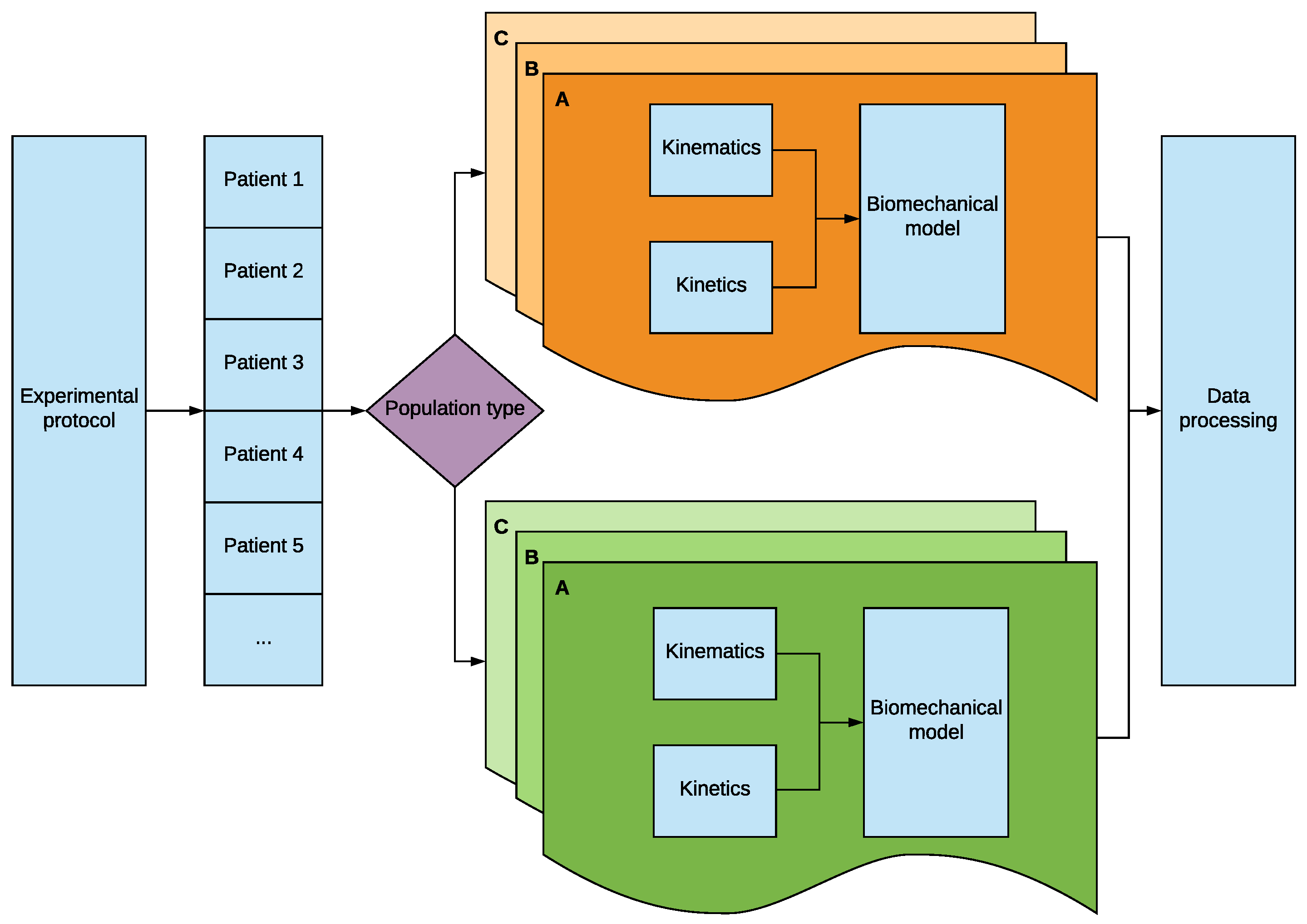
Figure 1.
Diagram of the methodology developed which allows to study different patient populations using several wheelchairs.
Figure 1.
Diagram of the methodology developed which allows to study different patient populations using several wheelchairs.
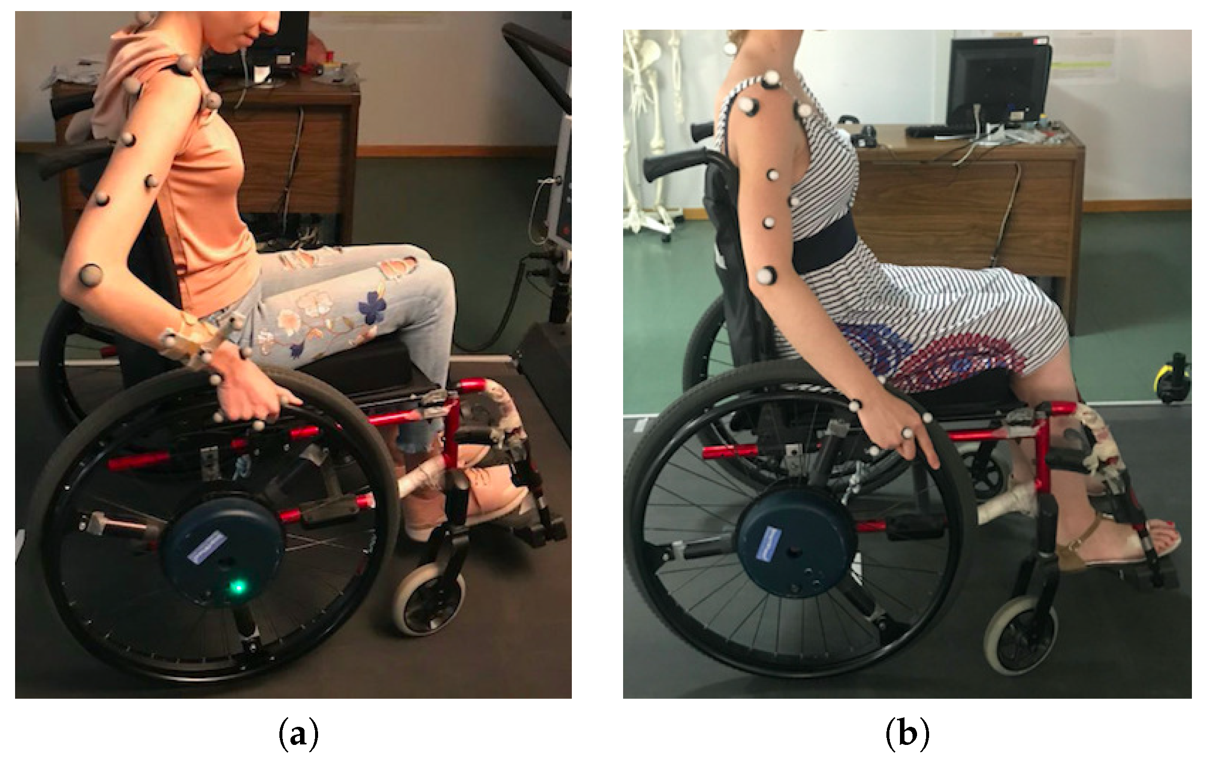
Figure 2.
(a) Initial and (b) final configuration of markers. (a) Three reference markers were included in the forearm to act as reference for the markers of the hand and the elbow as any marker needs a reference system with three markers; (b) The forearm reference markers were removed by referencing the markers of the elbow to the reference markers of the arm and the ones of the hand to the reference system of the hand itself.
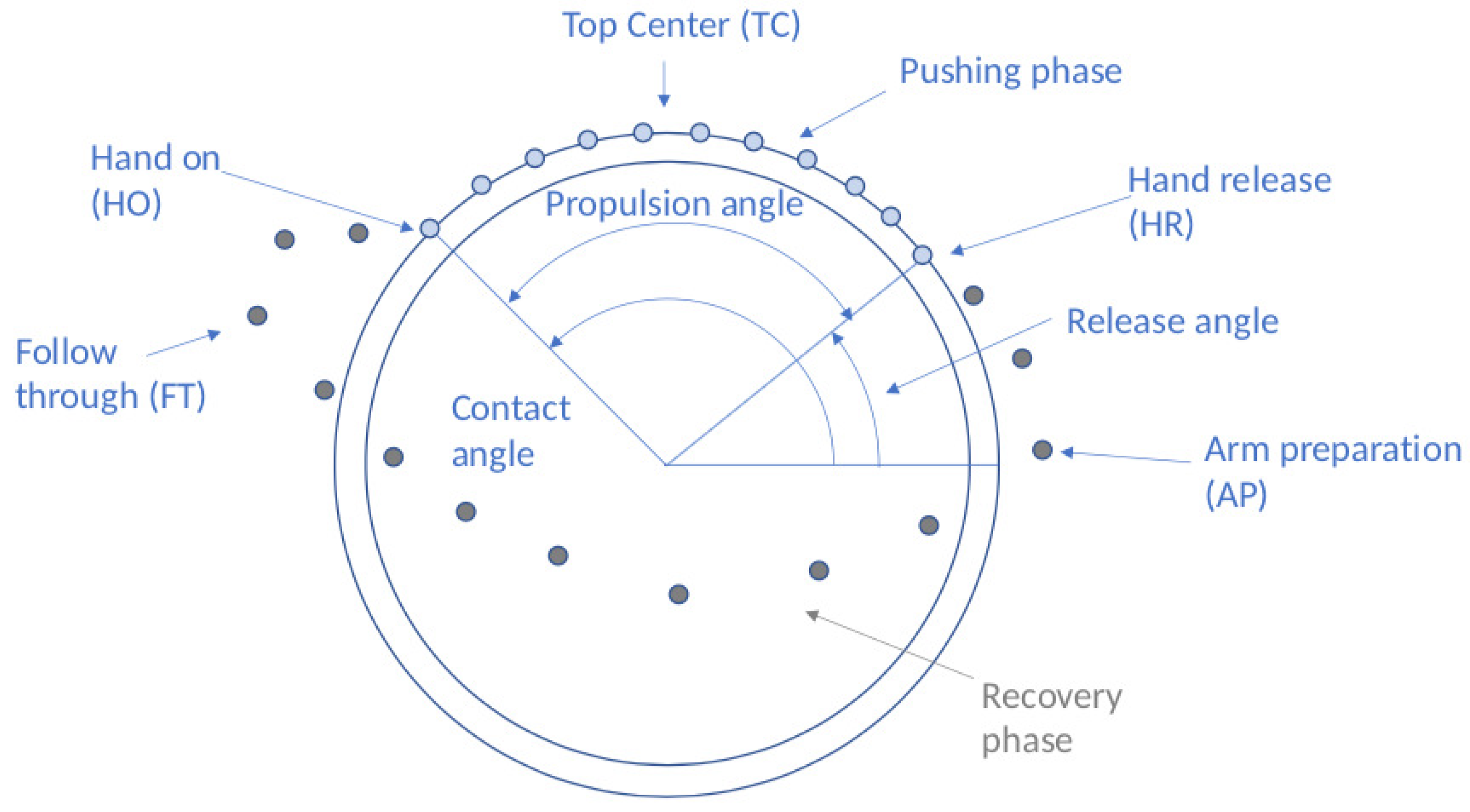
Figure 3.
Propulsion cycle with main contact points and angles. Points represent a discretized position of the hand on the different phases. Pushing phase on the ring in blue and recovery phase in the free space in grey.
Figure 3.
Propulsion cycle with main contact points and angles. Points represent a discretized position of the hand on the different phases. Pushing phase on the ring in blue and recovery phase in the free space in grey.
Figure 4.
Data gathering.
Figure 4.
Data gathering.
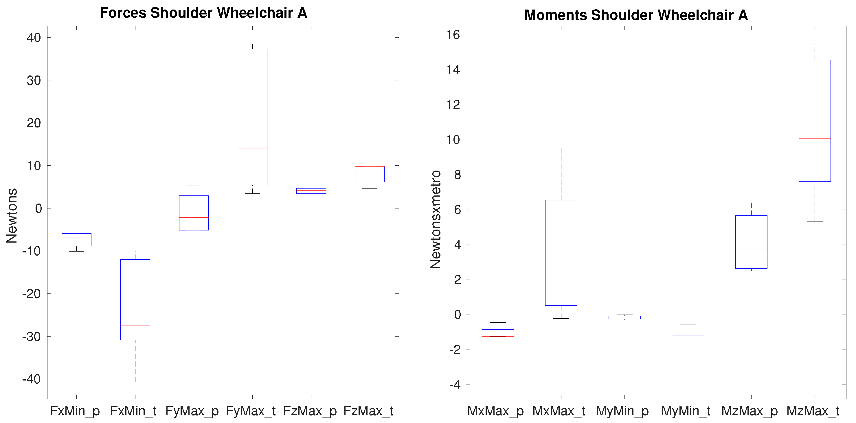
Figure 5.
Forces and moments that show significance on the shoulder between paraplegics and tetraplegics when propelling wheelchair A. represents the minimum value of posterior force on the shoulder, shows the maximum lateral force on the shoulder, represents the maximum superior force. shows the maximum value of the adduction moment, the minimum value of the extension moment and the maximum value of the internal rotation moment on the shoulder. In all cases, the values for paraplegics (_p) and tetraplegics (_t) are shown.
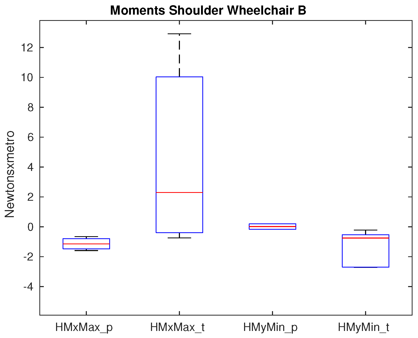
Figure 6.
Moments that show significance on the shoulder between paraplegics and tetraplegics when propelling wheelchair B. shows the maximum adduction moment on the shoulder and shows the minimum extension moment on the shoulder. In all cases, the values for paraplegics (_p) and tetraplegics (_t) are shown.
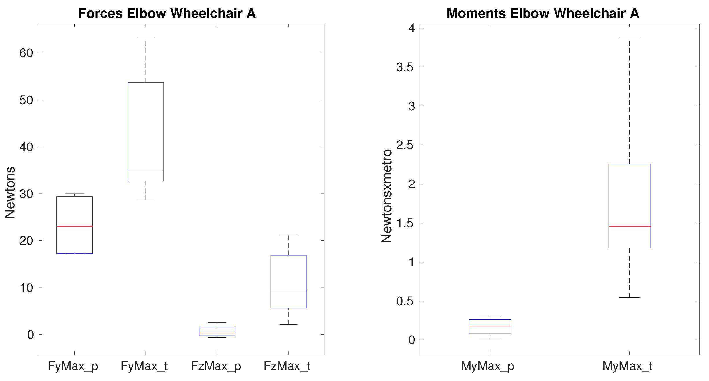
Figure 7.
Forces and moments that show significance on the elbow between paraplegics and tetraplegics when propelling wheelchair A. represents the maximum value of lateral force on the elbow, shows the maximum superior force on the elbow. shows the maximum value of the flexion moment. In all cases, the values for paraplegics (_p) and tetraplegics (_t) are shown.
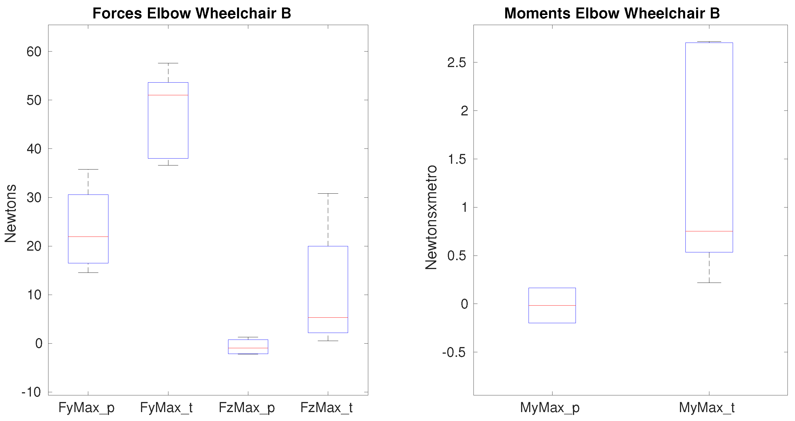
Figure 8.
Forces and moments that show significance on the elbow between paraplegics and tetraplegics when propelling wheelchair B. represents the maximum value of lateral force on the elbow, shows the maximum superior force on the elbow. shows the maximum value of the flexion moment. In all cases, the values for paraplegics (_p) and tetraplegics (_t) are shown.
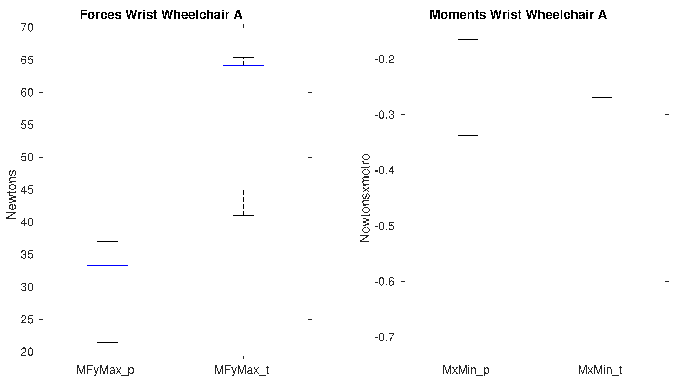
Figure 9.
Forces and moments that show significance on the wrist between paraplegics and tetraplegics when propelling wheelchair A. shows the maximum lateral force and shows the minimum radial moment on the wrist. In all cases, the values for paraplegics (_p) and tetraplegics (_t) are shown.
Figure 9.
Forces and moments that show significance on the wrist between paraplegics and tetraplegics when propelling wheelchair A. shows the maximum lateral force and shows the minimum radial moment on the wrist. In all cases, the values for paraplegics (_p) and tetraplegics (_t) are shown.
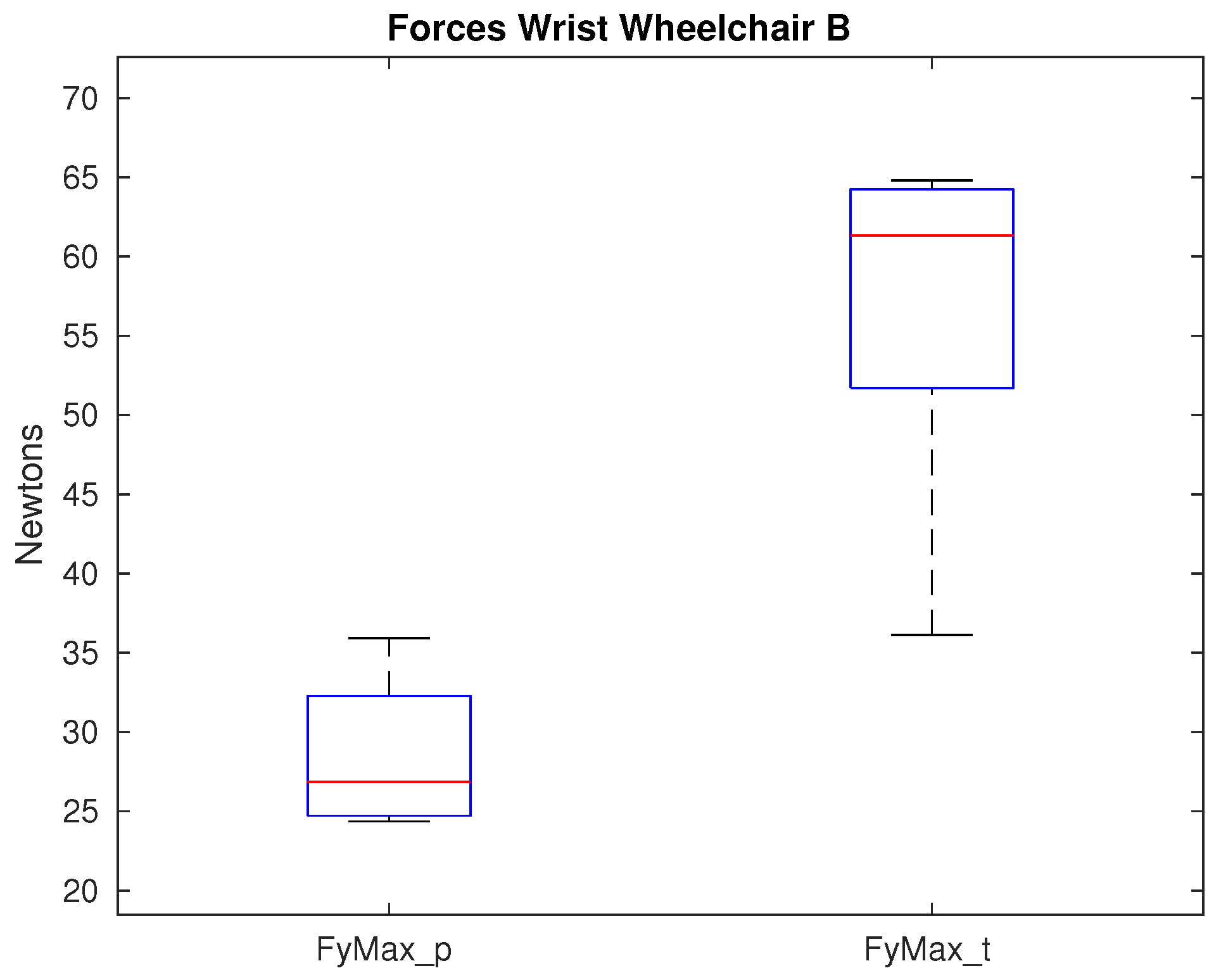
Figure 10.
Maximum lateral force that shows significance on the wrist between paraplegics and tetraplegics when propelling wheelchair B. Values for paraplegics (_p) and tetraplegics (_t) are shown.
Figure 10.
Maximum lateral force that shows significance on the wrist between paraplegics and tetraplegics when propelling wheelchair B. Values for paraplegics (_p) and tetraplegics (_t) are shown.
Table 1.
Wheelchairs (WCh) used for the experimental protocol.
Table 1.
Wheelchairs (WCh) used for the experimental protocol.
| Characteristics | WCh A | WCh B |
|---|
| Total height (cm) | 97.0 | 92.0 |
| Total width (cm) | 67.0 | 60.5 |
| Total depth (cm) | 95.0 | 88.0 |
| Seat-floor height (cm) | 48.0 | 44.0 |
| Seat-footrest height (cm) | 48.0 | 40.0 |
| Seat height (cm) | 43.0 | 38.0 |
| Seat width (cm) | 42.0 | 40.0 |
| Seat depth (cm) | 40.0 | 38.0 |
| Seat inclination () | 4.1 | 7.5 |
| Weight (kg) | 13.0 | 11.0 |
| Camber () | 0 | 0 |
| Wheel diameters (mm) | 600 | 600 |
Table 2.
Characteristics of the wheelchairs (WCh) of the participants.
Table 2.
Characteristics of the wheelchairs (WCh) of the participants.
| Participants | WCh Model | WCh Weight (kg) | WCh Seat Width (cm) | WCh Seat Depth (cm) |
|---|
| P01 | TiLite ZRA | 9 | 36 | 38 |
| P02 | Oracing | 9 | 41 | 43 |
| P03 | Kuschall K-4 | 9 | 40 | 41 |
| P04 | Action 3 | 13 | 40 | 41 |
| P05 | Action 3 | 13 | 40 | 41 |
| P06 | Panthera | 5.5 | 41 | 35 |
| P07 | Kuschall Champion | 10 | 38 | 38 |
| P08 | RGK Tiga | 10 | 37 | 37 |
| P09 | Action 3 | 13 | 42 | 42 |
| P10 | Action 3 | 13 | 40 | 40 |
Table 3.
Participants lesion characteristics.
Table 3.
Participants lesion characteristics.
| Participants | Gender | Lesion Level | Time Since Injury (Months) | A.S.I.A. | Type of Lesion | Group | |
|---|
| P01 | F | T6 | 28 | A | Complete | Paraplegic | (P) |
| P02 | M | T11 | 5 | C | Incomplete | Paraplegic | (P) |
| P03 | M | T1 | 555 | A | Complete | Paraplegic | (P) |
| P04 | F | T7 | 7 | B | Incomplete | Paraplegic | (P) |
| P05 | M | T5 | 5 | A | Complete | Paraplegic | (P) |
| P06 | M | C6-7 | 285 | A | Complete | Tetraplegic | (T) |
| P07 | M | C8 | 59 | A | Complete | Tetraplegic | (T) |
| P08 | M | C4 | 15 | D | Incomplete | Tetraplegic | (T) |
| P09 | M | C6-7 | 349 | A | Complete | Tetraplegic | (T) |
| P10 | M | C8 | 472 | A | Complete | Tetraplegic | (T) |
Table 4.
Biomechanical model.
Table 4.
Biomechanical model.
| Acronym | Description | Segment |
|---|
| c7 | Seventh cervical vertebra | Trunk |
| acrr | Right acromion-clavicular bone protrusion | Trunk |
| acrl | Left acromion-clavicular bone protrusion | Trunk |
| hha | Anterior point of humeral head | Trunk |
| hhp | Posterior point of humeral head | Trunk |
| rm1 | Reference marker on the arm number 1 | Arm |
| rm2 | Reference marker on the arm number 2 | Arm |
| rm3 | Reference marker on the arm number 3 | Arm |
| epc | External epicondyle | Arm |
| ipc | Internal epicondyle | Arm |
| ulr | Ulnar styloid | Hand |
| rdl | Radial styloid | Hand |
| 2m | Second metacarpus | Hand |
| 3m | Third metacarpus | Hand |
| 5m | Fifth metacarpus | Hand |
Table 5.
All variables analyzed in the procedure proposed divided in groups.
Table 5.
All variables analyzed in the procedure proposed divided in groups.
| Type of Variable | Description | Equation/Specifications |
|---|
| Temporal–spatial | Cadence: number of strokes per second | (st/s) |
| | Pushing phase: time elapsed since the hand-rim is held until it is released | (s) |
| | Recovery phase: times elapsed since the hand-rim is released until it is held again | (s) |
| | Quotient between the pushing and recovery phase | |
| | Distance covered in a propulsion cycle | (m) |
| | Contact angle: angle at which the hand-rim is held | CA () |
| | Release angle: angle at which the hand-rim is released | RA () |
| Kinetic in the hand-rim | Force in the reference system of the hand-rim | (N) |
| | Maximum total force in the hand-rim | (N) |
| | Maximum tangential force in the hand-rim | (N) |
| | Effective force | |
| | Elevation rate of the total force | (N/s) |
| | Moments in the reference system of the hand-rim | (Nm) |
| | Maximum total moment in the hand-rim | (Nm) |
| | Elevation rate of the total moment | (Nm/s) |
| Kinematic at joints (Value of joint’s position along the whole propulsion cycle: pushing and recovery phases) | Shoulder elevation: adduction-abduction | () |
| | Shoulder elevation plane: flexion-extension | () |
| | Shoulder internal rotation | () |
| | Elbow internal rotation | () |
| | Elbow flexion-extension | () |
| | Wrist ulnar-radial deviation | () |
| | Wrist internal rotation | () |
| | Wrist flexion-extension | () |
| Kinetic at joints (Value of joint’s forces and moments along the whole propulsion cycle: pushing and recovery phases) | Maximum and minimum forces | (N) |
| | Forces in HC, TC, HO, FT and AR | (N) |
| | Maximum and minimum moments | (Nm) |
| | Forces in HC, TC, HO, FT and AR | (Nm) |
Table 6.
Temporal–spatial variables (mean SD).
Table 6.
Temporal–spatial variables (mean SD).
| | Paraplegic Group | Tetraplegic Group |
|---|
| WCh A | WCh B | WCh A | WCh B |
|---|
| (st/s) | 1.25 | 1.04 | 1.05 | 1.14 |
| (m) | 0.72 | 0.82 | 0.83 | 0.77 |
| (s) | 0.34 | 0.41 | 0.44 | 0.43 |
| (s) | 0.55 | 0.59 | 0.57 | 0.50 |
| 0.65 | 0.71 | 0.80 | 0.86 |
| CA () | 113.86 | 111.27 | 110.83 | 110.01 |
| RA () | 112.67 | 110.09 | 108.56 | 108.06 |
Table 7.
Kinetic variables in the hand-rim (mean SD).
Table 7.
Kinetic variables in the hand-rim (mean SD).
| | Paraplegic Group | Tetraplegic Group |
|---|
| WCh A | WCh B | WCh A | WCh B |
|---|
| (N) | 47.00 | 48.20 | 93.16 | 118.37 |
| (N) | 36.12 | 38.98 | 43.18 | 48.61 |
| 0.76 | 0.81 | 0.49 | 000.49 |
| (N/s) | 908.87 | 816.95 | 2176.17 | 1958.45 |
| (Nm) | 9.28 | 10.02 | 11.10 | 12.49 |
| (Nm/s) | 212.48 | 180.83 | 227.37 | 222.50 |
Table 8.
Forces and moments that show significance on the shoulder (median IQR).
Table 8.
Forces and moments that show significance on the shoulder (median IQR).
| | Paraplegic Group | Tetraplegic Group |
|---|
| WCh A | WCh B | WCh A | WCh B |
|---|
| (N) | −6.80 | −4.72 | −27.48 | −16.44 |
| (N) | −2.20 | −2.72 | 13.93 | 18.52 |
| (N) | 4.17 | 4.84 | 9.78 | 8.25 |
| (Nm) | −1.25 | −0.94 | 1.92 | 2.30 |
| (Nm) | −0.18 | −0.05 | −1.46 | −0.75 |
| (Nm) | 3.80 | 5.31 | 10.08 | 13.60 |
Table 9.
Kinematic variables on the shoulder: maximum, minimum and ROM values (mean SD) and the propulsion phase in which they happen: pushing (p) or recovery phase (r).
Table 9.
Kinematic variables on the shoulder: maximum, minimum and ROM values (mean SD) and the propulsion phase in which they happen: pushing (p) or recovery phase (r).
| | Paraplegic Group | Tetraplegic Group |
|---|
| WCh A | WCh B | WCh A | WCh B |
|---|
| () | −27.18 (r) | −22.72 (p) | −28.45 (r) | −27.87 (r) |
| () | −39.09 (r) | −36.82 (r) | −45.83 (r) | −43.25 (r) |
| ROM () | 11.91 | 14.10 | 17.38 | 15.38 |
| () | 39.26 (r) | 20.27 (r) | 28.30 (r) | 46.09 (r) |
| () | −27.95 (r) | −56.26 (r) | −40.97 (r) | −20.08 (r) |
| ROM () | 67.21 | 76.53 | 69.27 | 66.17 |
| () | 28.14 (r) | 47.32 (r) | 47.90 (r) | 37.29 (r) |
| () | −32.75 (r) | −26.06 (r) | −17.15 (r) | −29.94 (r) |
| ROM () | 60.89 | 73.38 | 65.04 | 67.23 |
Table 10.
Forces and moments that show significance on the elbow (median IQR).
Table 10.
Forces and moments that show significance on the elbow (median IQR).
| | Paraplegic Group | Tetraplegic Group |
|---|
| WCh A | WCh B | WCh A | WCh B |
|---|
| (N) | 23.07 | 24.45 | 34.81 | 51.03 |
| (N) | 0.38 | −0.37 | 9.28 | 5.31 |
| (Nm) | 0.18 | 0.05 | 1.46 | 0.75 |
Table 11.
Kinematic variables on the elbow: maximum, minimum and ROM values (mean SD) and the propulsion phase in which they happen: pushing (p) or recovery phase (r).
Table 11.
Kinematic variables on the elbow: maximum, minimum and ROM values (mean SD) and the propulsion phase in which they happen: pushing (p) or recovery phase (r).
| | Paraplegic Group | Tetraplegic Group |
|---|
| WCh A | WCh B | WCh A | WCh B |
|---|
| () | 63.82 (p) | 66.08 (p) | 67.36 (p) | 70.50 (p) |
| () | 42.07 (r) | 41.38 (r) | 25.15 (r) | 34.73 (r) |
| ROM () | 21.76 | 24.70 | 42.21 | 35.77 |
| () | 124.22 (r) | 134.32 (r) | 127.17 (r) | 119.48 (r) |
| () | 98.44 (r) | 103.07 (r) | 66.37 (p) | 67.82 (p) |
| ROM () | 25.78 | 31.25 | 60.80 | 51.67 |
Table 12.
Forces and moments that show significance on the wrist (median IQR).
Table 12.
Forces and moments that show significance on the wrist (median IQR).
| | Paraplegic Group | Tetraplegic Group |
|---|
| WCh A | WCh B | WCh A | WCh B |
|---|
| (N) | 28.31 | 28.62 | 54.81 | 61.33 |
| (Nm) | −0.25 | −0.12 | −0.54 | −0.38 |
Table 13.
Kinematic variables on the wrist: maximum, minimum and ROM values (mean SD) and the propulsion phase in which they happen: pushing (p) or recovery phase (r).
Table 13.
Kinematic variables on the wrist: maximum, minimum and ROM values (mean SD) and the propulsion phase in which they happen: pushing (p) or recovery phase (r).
| | Paraplegic Group | Tetraplegic Group |
|---|
| WCh A | WCh B | WCh A | WCh B |
|---|
| () | 18.39 (r) | 19.20 (p) | 22.24 (p) | 19.37 (p) |
| () | 16.28 (r) | 22.80 (r) | 19.54 (r) | 20.99 (r) |
| ROM () | 6.23 | 9.32 | 6.74 | 10.33 |
| () | 10.85 (r) | 15.72 (p) | 11.43 (r) | 5.19 (r) |
| () | 19.50 (r) | 16.43 (r) | 25.03 (r) | 32.16 (p) |
| ROM () | 9.45 | 7.05 | 16.50 | 26.98 |

 ,
, 


