Efficient Location Service for a Mobile Sink in Solar-Powered Wireless Sensor Networks


Abstract
1. Introduction
1.1. Motivation
1.2. Preliminaries
1.3. Contribution
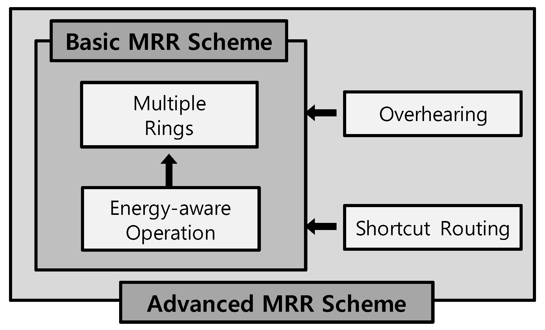
- The best utilization of harvested energy: each node can operate as a ring node only when it has surplus energy exceeding the amount of energy required for the general operation of a sensor node. This allows the MRR scheme to maximally exploit the periodically harvested solar energy.
- Enhancement of the data throughput: by efficiently maintaining multiple rings, the energy required for acquiring the location information of a sink node can be dramatically reduced. This conserved energy can be used to increase the amount of data collected at the sink.
- High scalability: owing to the multiple rings, the overhead required for acquiring the location information of the sink node hardly increases even if the network size becomes larger. This is a necessary requirement for large-scale WSN applications.
- Support for high mobility sinks: the transference of data to the fast sink node exhibits inevitably high failure rates. The MRR scheme prevents this problem to some extent by efficiently forwarding data to the recently moved sink node using the follow-up mechanism with shortcut routing.
2. Related Work
2.1. Energy Optimization for Solar-Powered WSNs
2.2. Location Management for a Mobile Sink
- LBDD (Line-Based Data Dissemination) [24]: In LBDD, nodes between two straight lines in the center of the network are called inline nodes, and these share the location information of a mobile sink. A source node that wants to deliver data to a sink node simply transmits data to these inline nodes, and the inline node that has received the data routes it to the mobile sink.
- Railroad [25]: RailRoad is a data dissemination architecture for large-scale WSNs. The RailRoad system proactively exploits a virtual infrastructure called a Rail, which is an area where all the metadata of events is stored. There is only one Rail in a network, and it acts as a rendezvous area for events and queries. The Rail is placed in the middle area of the field, so that every node can easily access it. Once a query is issued, it circulates around the Rail and searches relevant data stored in the Rail. When relevant metadata is found, the source node of the data transmits the corresponding data to the sink node that issued the query.
3. Proposed MRR Scheme
3.1. Overview of the MRR Scheme
3.2. Energy Model
3.3. Management of Multiple Rings
3.3.1. Ring Construction
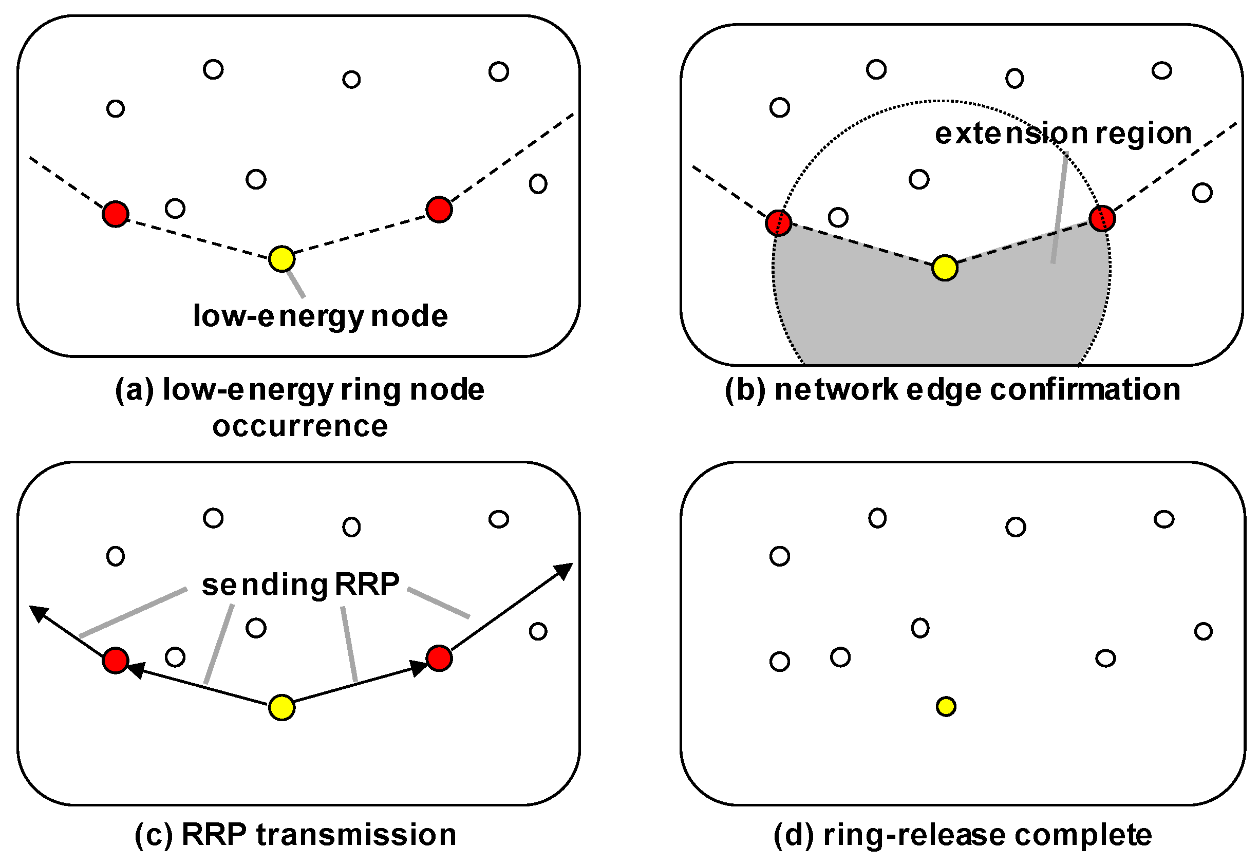
3.3.2. Ring Extension
- To extend the ring, the low-energy ring node announces the ring extension to the neighboring ring node in its CCW region (called the CCW ring node). At this time, the information on both the neighboring nodes in the extension region and the neighboring ring node in the CW region (called the CW ring node) are both provided. The extension region refers to the region swept out in the clockwise direction between the CCW ring node and the CW ring node, which constitutes a region outside of the ring within the transmission range of the node.
- The CCW ring node that has been notified of the ring extension finds the nodes satisfying Equation (4) among the candidate nodes in the extension region. Of course, there may or may not be any corresponding nodes. If at least one node is found, then the CCW ring node determines the most energy-efficient path containing these nodes from itself to the CW ring node, and the nodes on this path are designated as new ring nodes. On the other hand, if there are no corresponding nodes then the CCW ring node chooses the node with the most residual energy among the candidate nodes as a new ring node. This is possible because the CCW ring node receives all the information of nodes in extension region and the CW ring node. Finally, the CCW ring node sends a control packet to the CW ring node through these new ring nodes.
- When receiving the control packet, the CW ring node notifies the low-energy ring node that the ring extension is completed. Then, the low-energy ring node changes its role to a basic node.
3.3.3. Release of Ring
3.4. Data Routing to the Mobile Sink with Multiple Rings
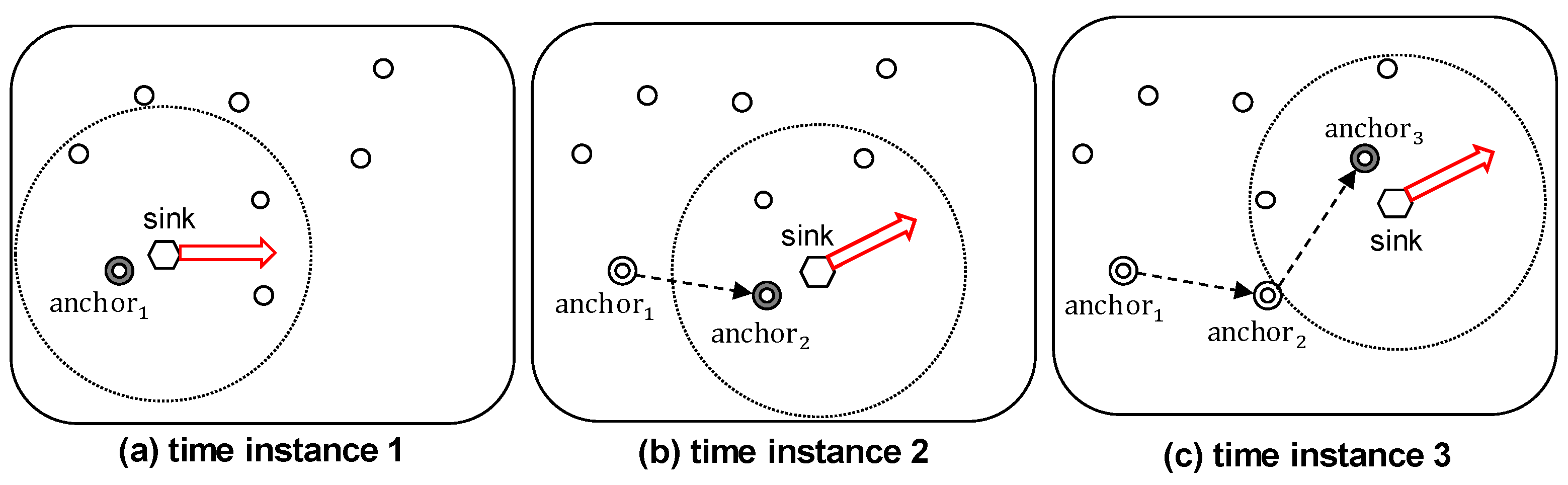
3.4.1. Anchor Node Selection
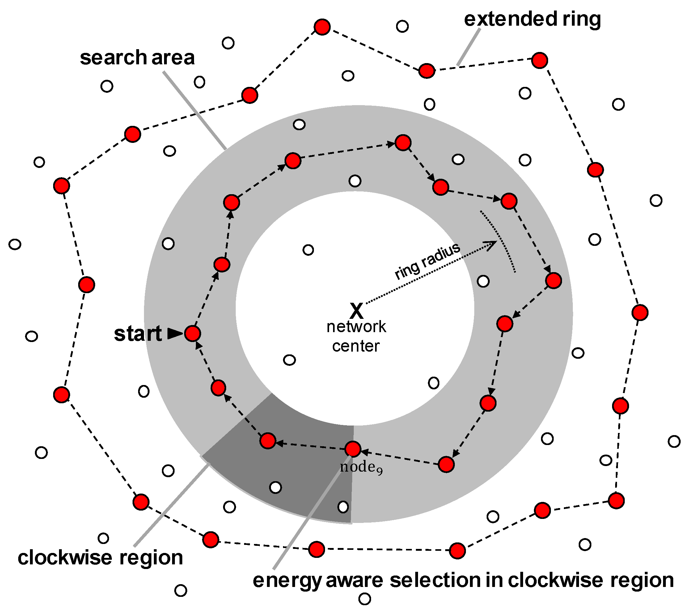
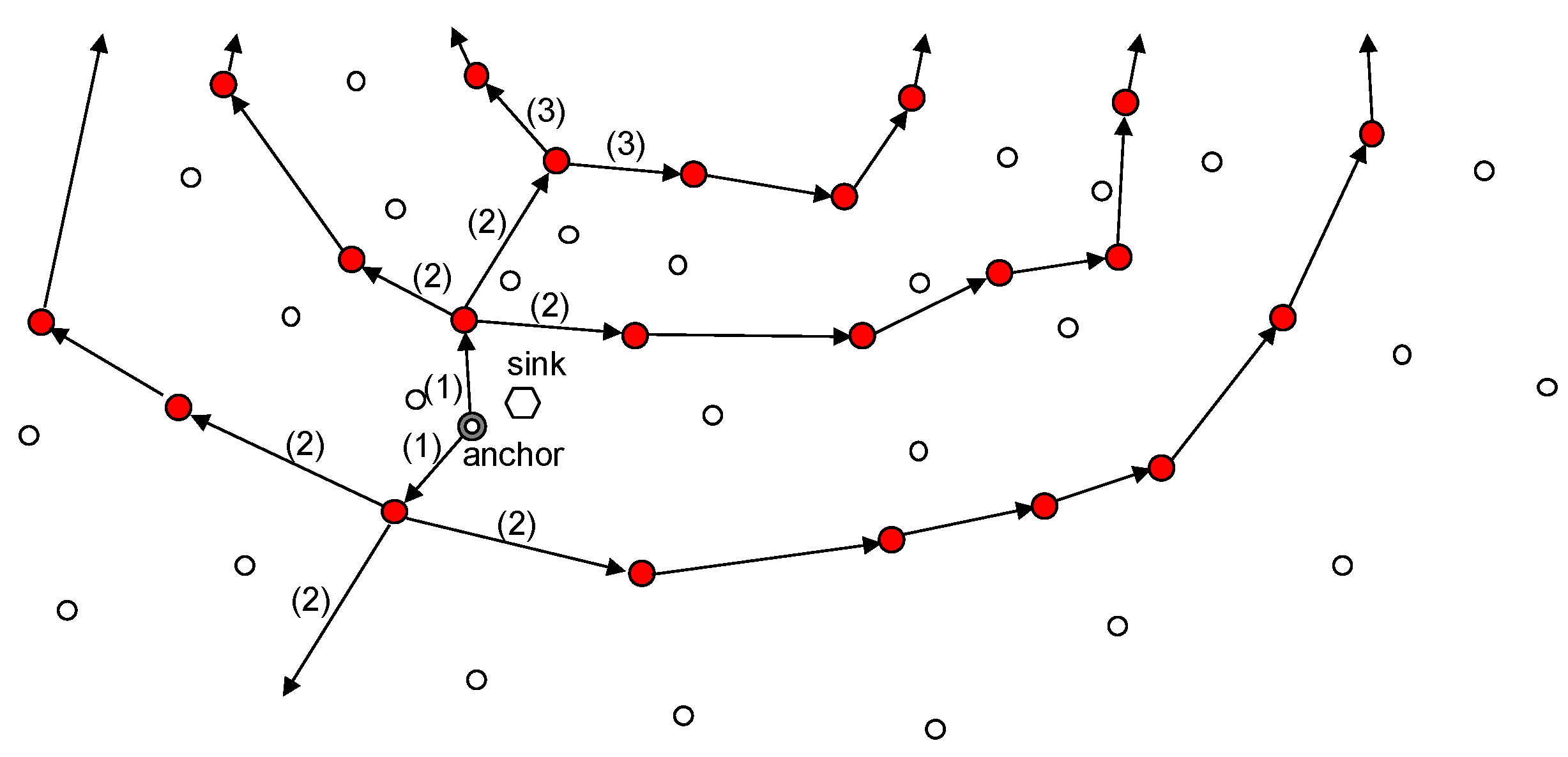
3.4.2. Advertising Anchor Node’s Location
- If a ring node receives the information packet from other node instead of neighboring CW or CCW ring nodes, it transmits the packet to its neighboring ring nodes on both the CW and CCW sides. Simultaneously, it also forwards the packet in the direction in which the packet was originally travelling (i.e., the center or outside of the network).
- If a ring node receives the information packet from one of its neighboring ring nodes, it transmits data to the opposite-side ring node.
- If a ring node receives the same information packet from both of two neighboring ring nodes, it sends a sink location packet no longer because this means that all ring nodes belonging to that ring have received this packet.
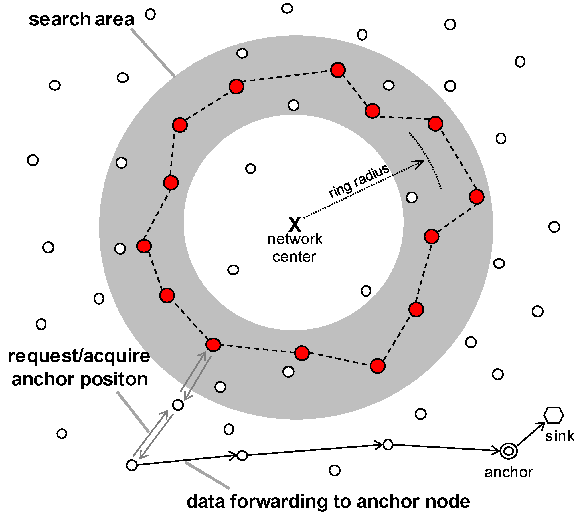
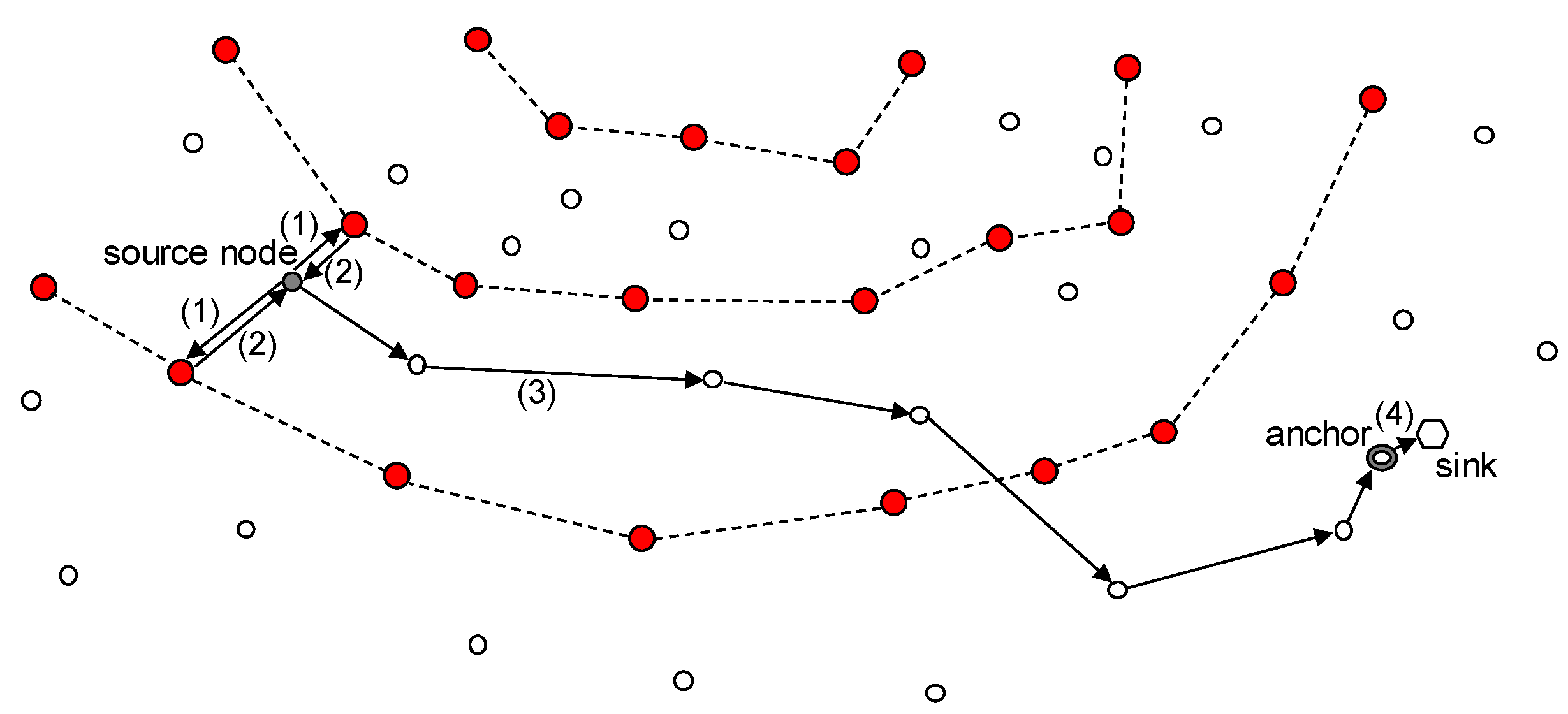
3.4.3. Delivery of Data to the Sink Node
- The source node sends a location information request packet in the direction of the network center and the opposite direction in order to obtain the location information. This ensures that at least one ring node receives the packet.
- The source node can obtain the location information for the anchor node by receiving the response packet from a ring node.
- It then sends data to the anchor node using the location-based routing scheme.
- The anchor node transmits the received data to the nearby sink.
4. Advanced MRR Scheme
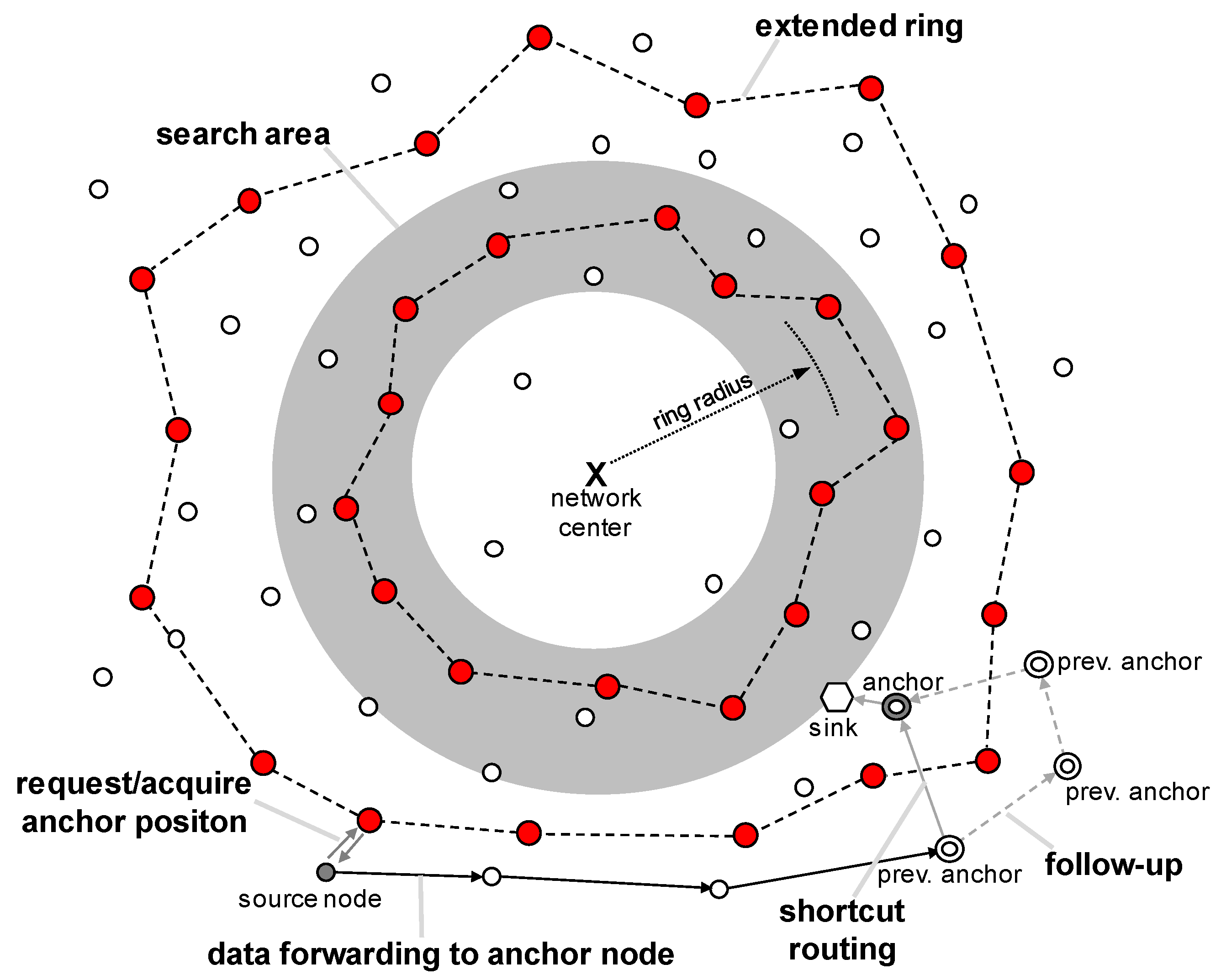
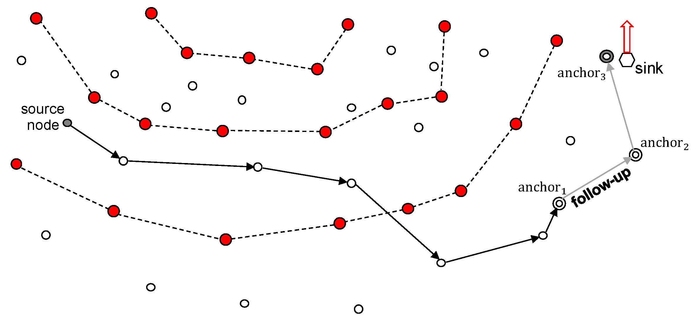
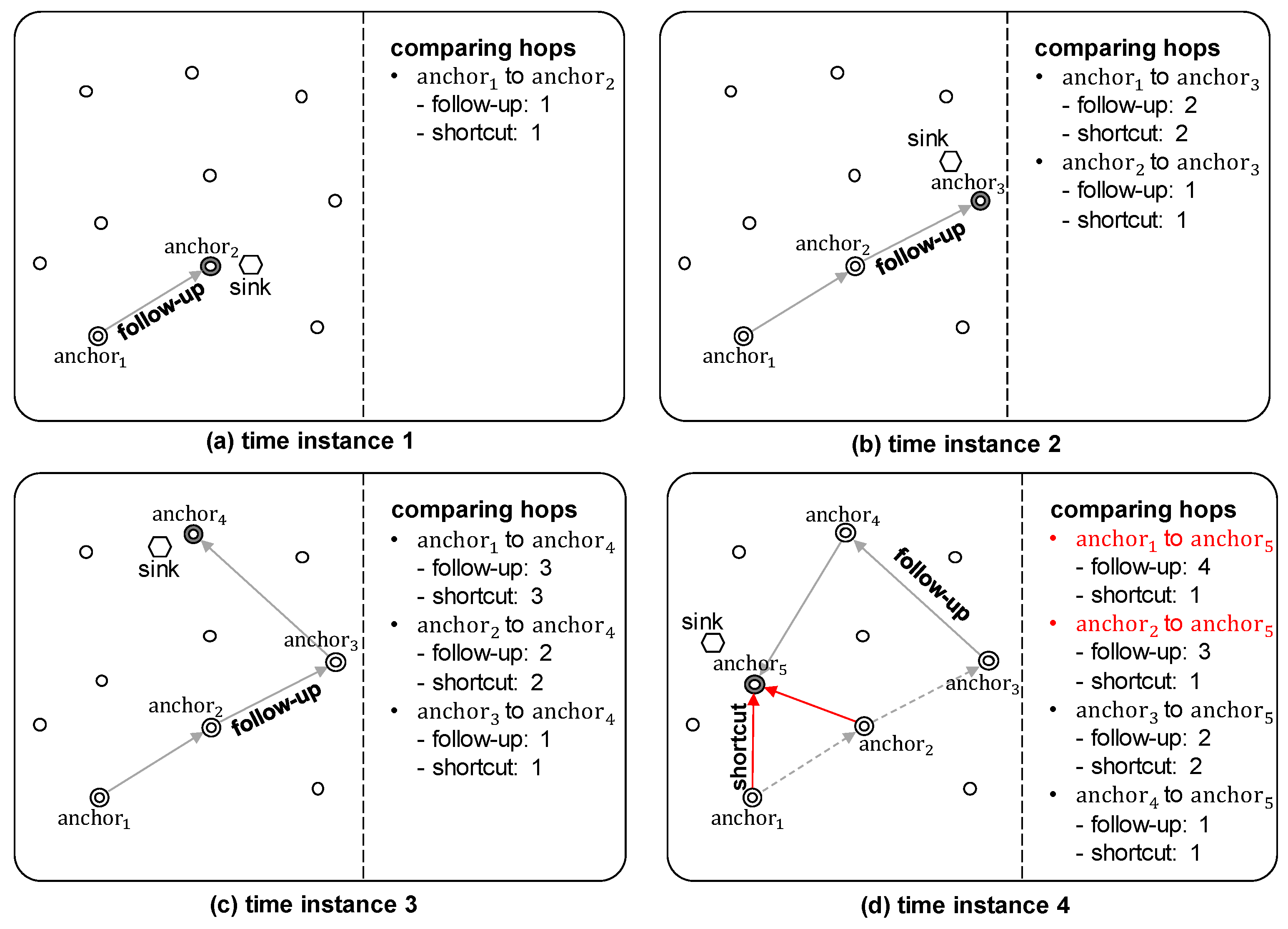
4.1. Follow-Up Mechanism with Shortcut Routing
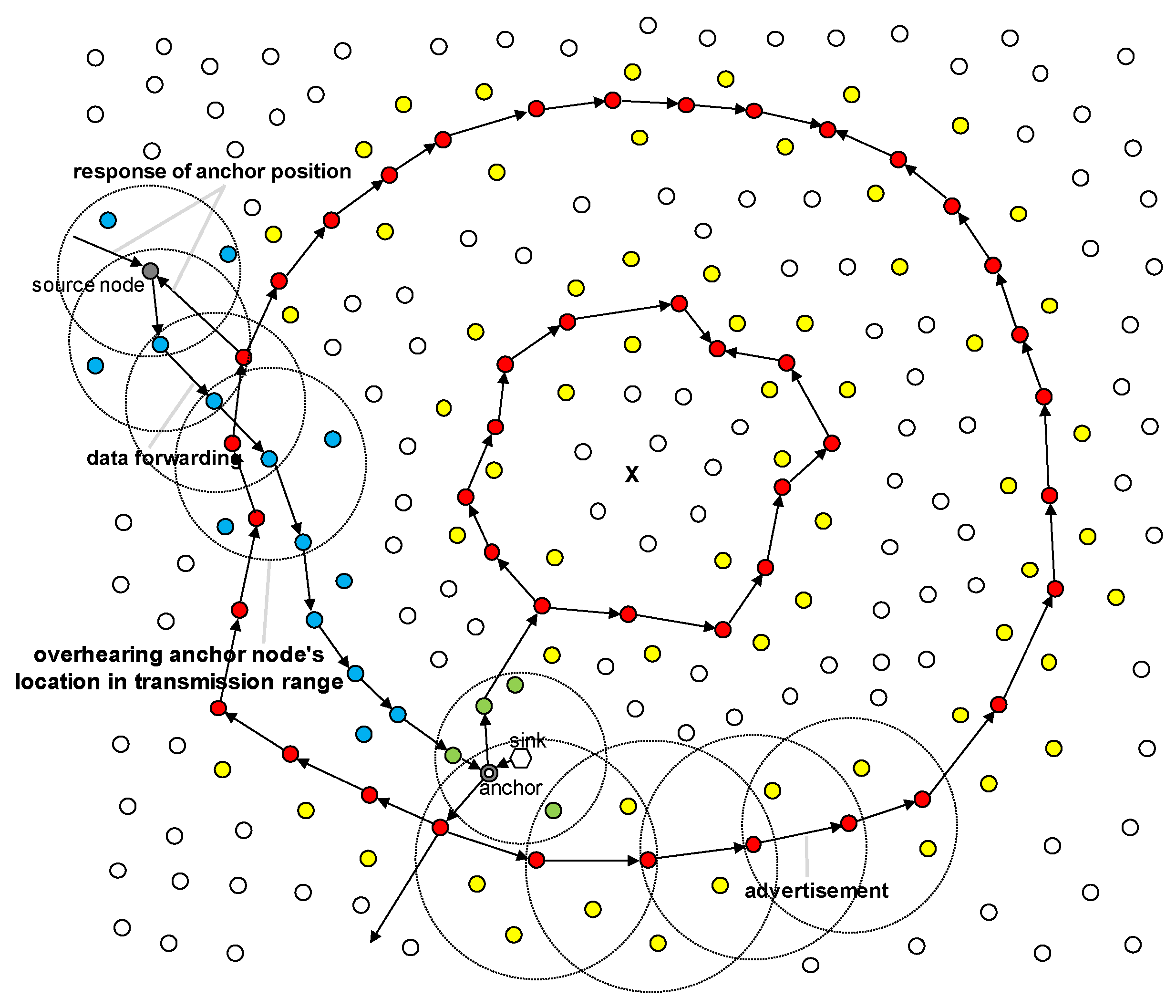
4.2. Overhearing Anchor’s Position
- Anchor node selection: When the sink selects an anchor node, nodes close to the sink node can obtain location information for the anchor node by overhearing packets transmitted between the sink node and anchor node (the green node in Figure 12).
- Advertisement of the anchor node’s location: When the anchor node informs the ring of its location information and when this location information is shared between the ring nodes, nodes on the transmission path can obtain the location information (yellow nodes in Figure 12).
- Data forwarding: When the source node receives location information from the ring for data transmission, nodes on the path between the source and ring node and their neighbors can obtain the location information. In addition, when the source node sends data to the anchor node, nodes on the path and their neighbors can also obtain the location information (blue nodes in Figure 12).
5. Performance Evaluation
5.1. Simulation Environments
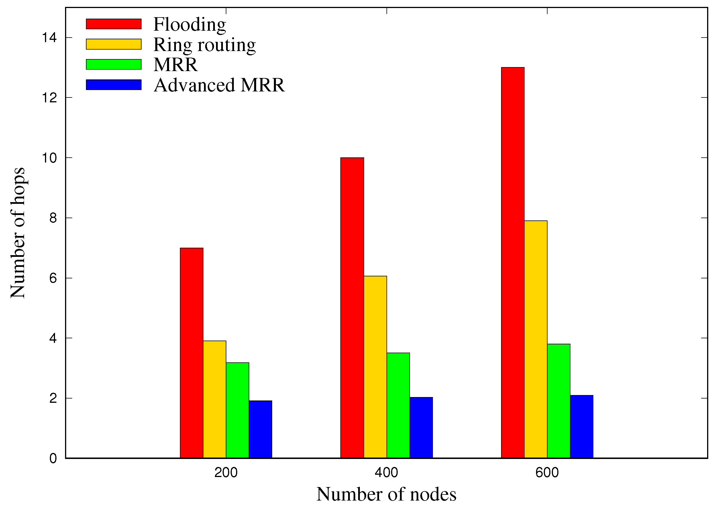
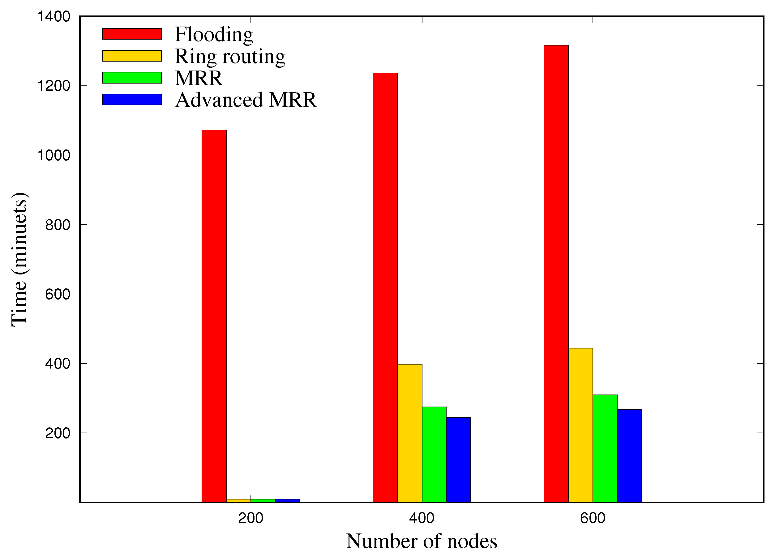
5.2. Scalability
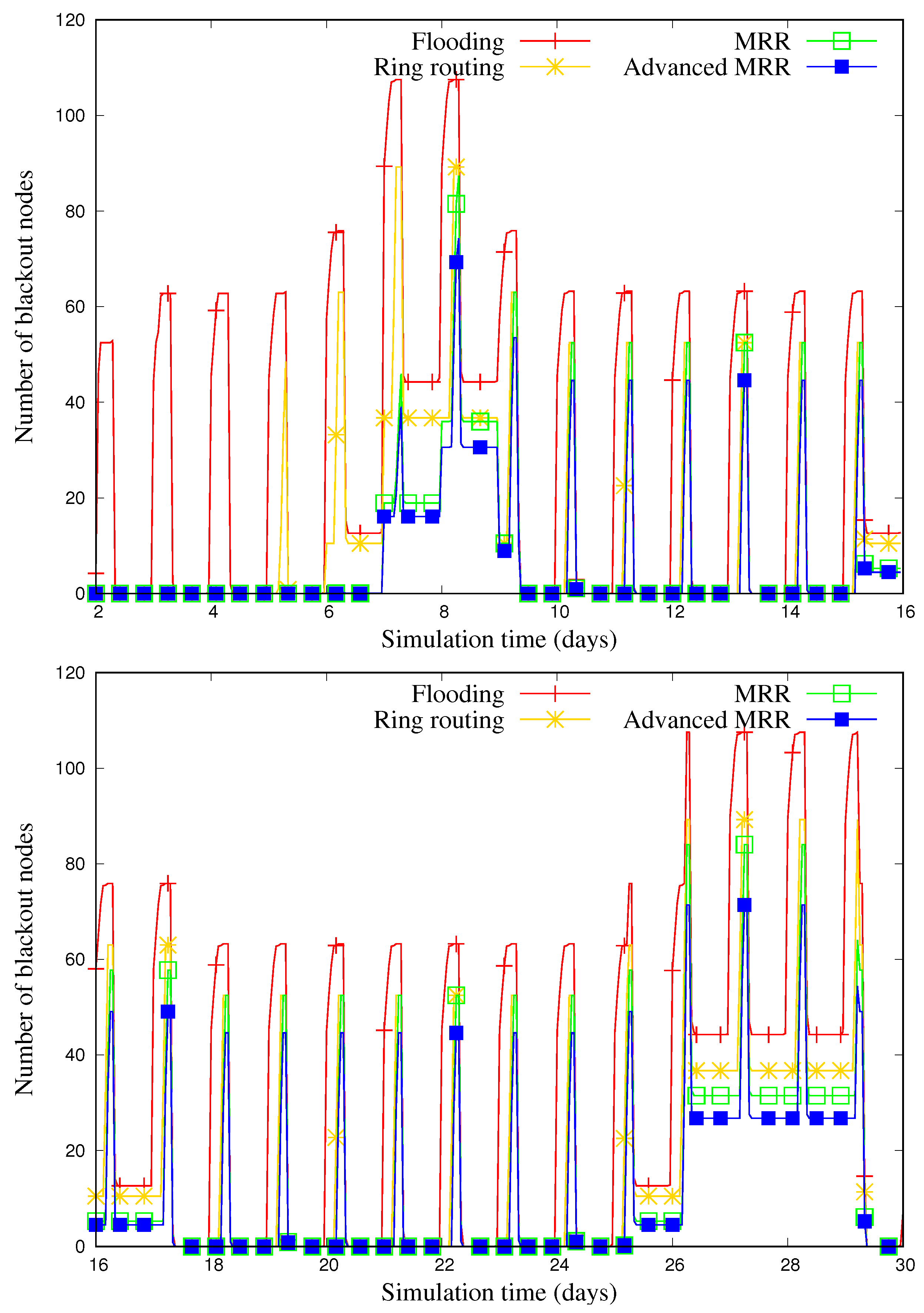
5.3. Blackout Nodes
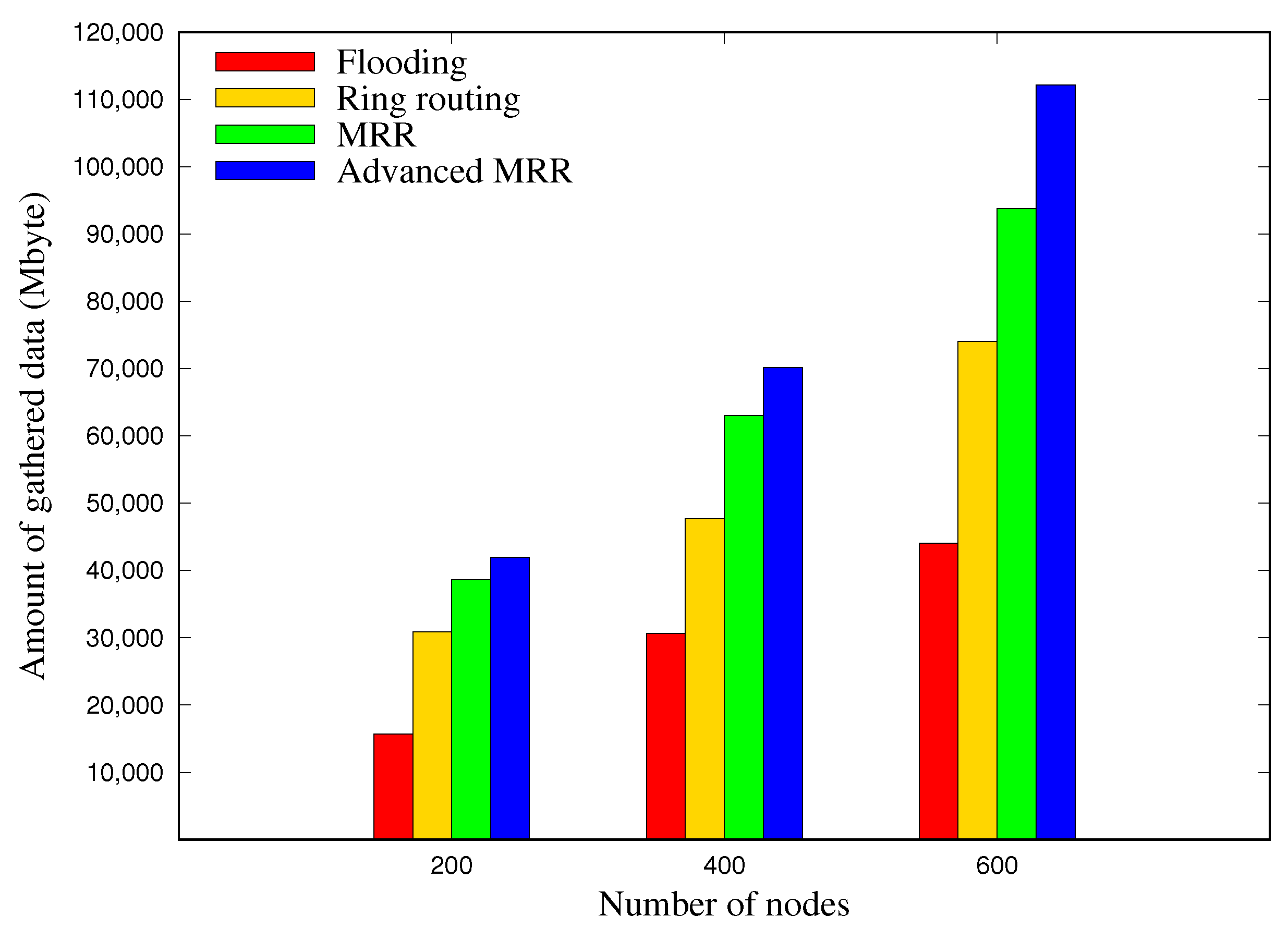
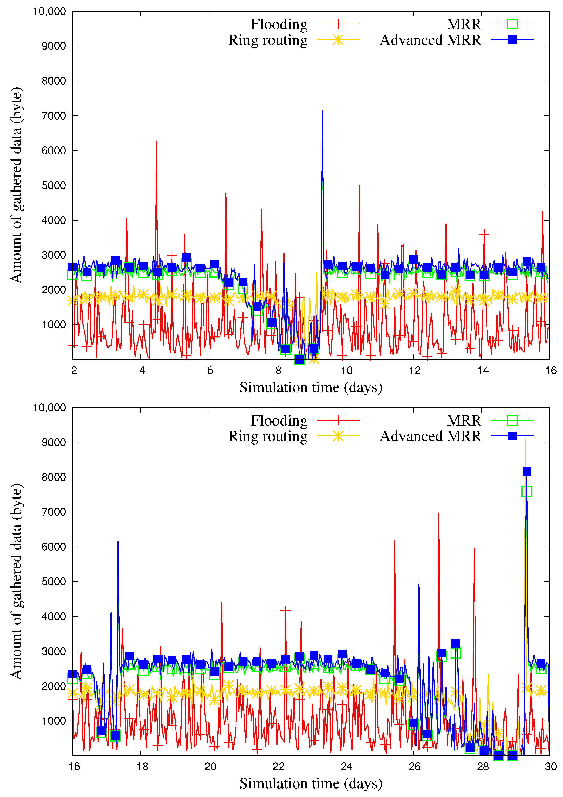
5.4. Amount of Collected Data
6. Conclusions
Author Contributions
Funding
Conflicts of Interest
References
- Yick, J.; Mukherjee, B.; Ghosal, D. Wireless Sensor Network Survey. Comput. Netw. 2008, 52, 2292–2330. [Google Scholar] [CrossRef]
- Akyildiz, I.F.; Su, W.; Sankarasubramaniam, Y.; Cayirci, E. Wireless Sensor Networks: A Survey. Comput. Netw. 2002, 38, 393–422. [Google Scholar] [CrossRef]
- Sudevalayam, S.; Kulkarni, P. Energy Harvesting Sensor Nodes: Survey and Implications. IEEE Commun. Surv. Tutor. 2011, 13, 443–461. [Google Scholar] [CrossRef]
- Tunca, C.; Isik, S.; Donmez, M.Y.; Ersoy, C. Distributed Mobile Sink Routing for Wireless Sensor Networks: A Survey. IEEE Commun. Surv. Tutor. 2014, 16, 877–897. [Google Scholar] [CrossRef]
- Tunca, C.; Isik, S.; Donmez, M.Y.; Ersoy, C. Ring Routing: An Energy-Efficient Routing Protocol for Wireless Sensor Networks with a Mobile Sink. IEEE Trans. Mob. Comput. 2015, 14, 1947–1960. [Google Scholar] [CrossRef]
- Wan, Z.G.; Tan, Y.K.; Yuen, C. Review on Energy Harvesting and Energy Management for Sustainable Wireless Sensor Networks. In Proceedings of the 13th International Conference on Communication Technology, Jinan, China, 25–28 September 2011; pp. 362–367. [Google Scholar]
- Kansal, A.; Hsu, J.; Zahedi, S.; Srivastava, M.B. Power Management in Energy Harvesting Sensor Networks. Trans. Embed. Comput. Syst. 2007, 6, 32. [Google Scholar] [CrossRef]
- Kansal, A.; Potter, D.; Srivastava, M.B. Performance Aware Tasking for Environmentally Powered Sensor Networks. Sigmetrics Perform. Eval. Rev. 2004, 32, 223–234. [Google Scholar] [CrossRef]
- Melodia, T.; Pompili, D.; Akyildiz, I.F. Optimal Local Topology Knowledge for Energy Efficient Geographical Routing in Sensor Networks. In Proceedings of the 23rd International Conference on Computer Communications, Hong Kong, China, 7–11 March 2004; pp. 1705–1716. [Google Scholar]
- Piorno, J.R.; Bergonzini, C.; Atienza, D.; Rosing, T.S. Prediction and Management in Energy Harvested Wireless Sensor Nodes. In Proceedings of the 1st International Conference on Wireless Communication, Vehicular Technology, Information Theory and Aerospace & Electronic Systems Technology, Aalborg, Denmark, 17–20 May 2009; pp. 6–10. [Google Scholar]
- Bergonzini, C.; Brunelli, D.; Benini, L. Comparison of Energy Intake Prediction Algorithms for Systems Powered by Photovoltaic Harvesters. Microelectron. J. 2010, 41, 766–777. [Google Scholar] [CrossRef]
- Cammarano, A.; Petrioli, C.; Spenza, D. Pro-Energy: A Novel Energy Prediction Model for Solar and Wind Energy-Harvesting Wireless Sensor Networks. In Proceedings of the 9th International Conference on Mobile Ad-Hoc and Sensor Systems, Las Vegas, NV, USA, 8–11 October 2012; pp. 75–83. [Google Scholar]
- Kosunalp, S. A New Energy Prediction Algorithm for Energy-Harvesting Wireless Sensor Networks with Q-Learning. IEEE Access 2016, 4, 5755–5763. [Google Scholar] [CrossRef]
- Noh, D.K.; Abdelzaher, F.T. Efficient Flow-control Algorithm Cooperating with Energy Allocation Scheme for Solar-powered WSNs. Wirel. Commun. Mob. Comput. 2012, 12, 379–392. [Google Scholar] [CrossRef]
- Zhang, Y.; He, S.; Chen, J. Data Gathering Optimization by Dynamic Sensing and Routing in Rechargeable Sensor Networks. Trans. Netw. 2016, 24, 1632–1646. [Google Scholar] [CrossRef]
- Yoon, I.; Kim, H.; Noh, D.K. Adaptive Data Aggregation and Compression to Improve Energy Utilization in Solar-Powered Wireless Sensor Networks. Sensors 2017, 17, 1226. [Google Scholar] [CrossRef] [PubMed]
- Khan, M.I.; Gansterer, W.N.; Haring, G. Static vs. Mobile sink: The Influence of Basic Parameters on Energy Efficiency in Wireless Sensor Networks. Comput. Commun. 2013, 36, 965–978. [Google Scholar] [CrossRef] [PubMed]
- Luo, H.; Ye, F.; Cheng, J.; Lu, S.; Zhang, L. TTDD: Two-Tier Data Dissemination in Large-Scale Wireless Sensor Networks. Wirel. Netw. 2005, 11, 161–175. [Google Scholar] [CrossRef]
- Kweon, K.; Ghim, H.; Hong, J.; Yoon, H. Grid-Based Energy-Efficient Routing from Multiple Sources to Multiple Mobile Sinks in Wireless Sensor Networks. In Proceedings of the 4th International Symposium on Wireless Pervasive Computing, Melbourne, VIC, Australia, 11–13 Feburary 2009; pp. 1–5. [Google Scholar]
- Chang, S.H.; Merabti, M.; Mokhtar, H.M. Coordinate Magnetic Routing for Mobile Sinks Wireless Sensor Networks. In Proceedings of the 21st International Conference on Advanced Information Networking and Applications Workshops, Niagara Falls, ON, Canada, 21–23 May 2007; Volume 1, pp. 846–851. [Google Scholar]
- Lin, C.J.; Chou, P.L.; Chou, C.F. HCDD: Hierarchical Cluster-Based Data Dissemination in Wireless Sensor Networks with Mobile Sink. In Proceedings of the International Conference on Wireless Communications and Mobile Computing, Vancouver, BC, Canada, 3–6 July 2006; pp. 1189–1194. [Google Scholar]
- Yuan, X.X.; Zhang, R.H. An Energy-Efficient Mobile Sink Routing Algorithm for Wireless Sensor Networks. In Proceedings of the 7th International Conference on Wireless Communications, Networking and Mobile Computing, Wuhan, China, 23–25 September 2011; pp. 1–4. [Google Scholar]
- Nazir, B.; Hasbullah, H. Mobile Sink Based Routing Protocol (MSRP) for Prolonging Network Lifetime in Clustered Wireless Sensor Network. In Proceedings of the International Conference on Computer applications and industrial electronics, Kuala Lumpur, Malaysia, 5–8 December 2010; pp. 624–629. [Google Scholar]
- Hamida, E.B.; Chelius, G. A Line-Based Data Dissemination Protocol for Wireless Sensor Networks with Mobile Sink. In Proceedings of the International Conference on Communications, Beijing, China, 19–23 May 2008; pp. 2201–2205. [Google Scholar]
- Shin, J.H.; Kim, J.; Park, K.; Park, D. Railroad: Virtual Infrastructure for Data Dissemination in Wireless Sensor Networks. In Proceedings of the 2nd ACM International Workshop on Performance Evaluation of Wireless Ad Hoc, Sensor, and Ubiquitous Networks, Montreal, QC, Canada, 10–13 October 2005; pp. 168–174. [Google Scholar]
- Yang, Y.; Wang, L.; Noh, D.K.; Le, H.K.; Abdelzaher, T.F. Solarstore: Enhancing Data Reliability in Solar-Powered Storage-Centric Sensor Networks. In Proceedings of the 7th International Conference on Mobile Systems, Applications, and Services, Kraków, Poland, 22–25 June 2009; pp. 333–346. [Google Scholar]
- Yi, J.M.; Kang, M.J.; Noh, D.K. SolarCastalia: Solar Energy Harvesting Wireless Sensor Network Simulator. Int. J. Distrib. Sens. Netw. 2015, 11, 415174. [Google Scholar] [CrossRef]
- Johnson, M.; Healy, M.; van de Ven, P.; Hayes, M.J.; Nelson, J.; Newe, T.; Lewis, E. A Comparative Review of Wireless Sensor Network Mote Technologies. In Proceedings of the International Conference on Sensors, Christchurch, New Zealand, 25–28 October 2009; pp. 1439–1442. [Google Scholar]
- Texas, I. EZ430-RF2500 Development Tool User’s Guide; Texas Instruments SLAU227E; Texas Instruments Incorporate: Austin, TX, USA, 2007. [Google Scholar]
- Himann, J.E.; Cunningham, D.A.; Rechnitzer, P.A.; Paterson, D.H. Age-related Changes in Speed of Walking. Med. Sci. Sports Exerc. 1988, 20, 161–166. [Google Scholar] [CrossRef] [PubMed]


| Contribution | Increasing Solar Energy Utilization | Decreasing Blackout Time | Increasing Data Throughput | Enhancing Network Scalability | Supporting Sink’s High Mobility | |
|---|---|---|---|---|---|---|
| Sub-Methods | ||||||
| Energy-aware operation | ⋁ | |||||
| Multiple rings | ⋁ | ⋁ | ⋁ | |||
| Overhearing method | ⋁ | ⋁ | ||||
| Shortcut routing method | ⋁ | |||||
| Energy Harvester | Power Density | |
|---|---|---|
| Indoor/Human Condition | Outdoor/Industrial Condition | |
| Solar panel | 100 irradiance | 10 irradiance |
| Wind turbine generator | 35 wind speed | 3.5 wind speed |
| Thermoelectric generator | 100 gradient | 3.5 gradient |
| Electromagnetic generator | 4 human motion-Hz | 800 machine-kHz |
| Parameter | Value |
|---|---|
| Number of nodes | 200∼600 |
| Size of topology | 4900∼14,884 |
| Deployment | Random |
| Weather | Randomly selected (sunny, cloudy, or rainy) |
| Average energy harvesting rate | 33.5 |
| Transmission range | 10 |
| Energy consumption rate for Data TX | 0.16704 |
| Energy consumption rate for Data RX | 0.18912 |
| Baud rate | 250 |
| Sensing data size | 32 |
| Battery capacity | 200 |
| Avg. speed of mobile sink | 1 |
| Moving direction of mobile sink | Random |
| simulation time | 30 |
| Scheme | Flooding | Ring Routing | MRR | Advanced MRR | |
|---|---|---|---|---|---|
| # of Nodes | |||||
| 200 | N/A | 1 | 1.556 | 1.648 | |
| 400 | N/A | 1 | 2.408 | 2.466 | |
| 600 | N/A | 1 | 4.060 | 4.211 | |
© 2019 by the authors. Licensee MDPI, Basel, Switzerland. This article is an open access article distributed under the terms and conditions of the Creative Commons Attribution (CC BY) license (http://creativecommons.org/licenses/by/4.0/).
Share and Cite
Kang, M.; Yoon, I.; Noh, D.K. Efficient Location Service for a Mobile Sink in Solar-Powered Wireless Sensor Networks. Sensors 2019, 19, 272. https://doi.org/10.3390/s19020272
Kang M, Yoon I, Noh DK. Efficient Location Service for a Mobile Sink in Solar-Powered Wireless Sensor Networks. Sensors. 2019; 19(2):272. https://doi.org/10.3390/s19020272
Chicago/Turabian StyleKang, Minjae, Ikjune Yoon, and Dong Kun Noh. 2019. "Efficient Location Service for a Mobile Sink in Solar-Powered Wireless Sensor Networks" Sensors 19, no. 2: 272. https://doi.org/10.3390/s19020272
APA StyleKang, M., Yoon, I., & Noh, D. K. (2019). Efficient Location Service for a Mobile Sink in Solar-Powered Wireless Sensor Networks. Sensors, 19(2), 272. https://doi.org/10.3390/s19020272