A Virtual Pressure and Force Sensor for Safety Evaluation in Collaboration Robot Application †

Abstract
1. Introduction
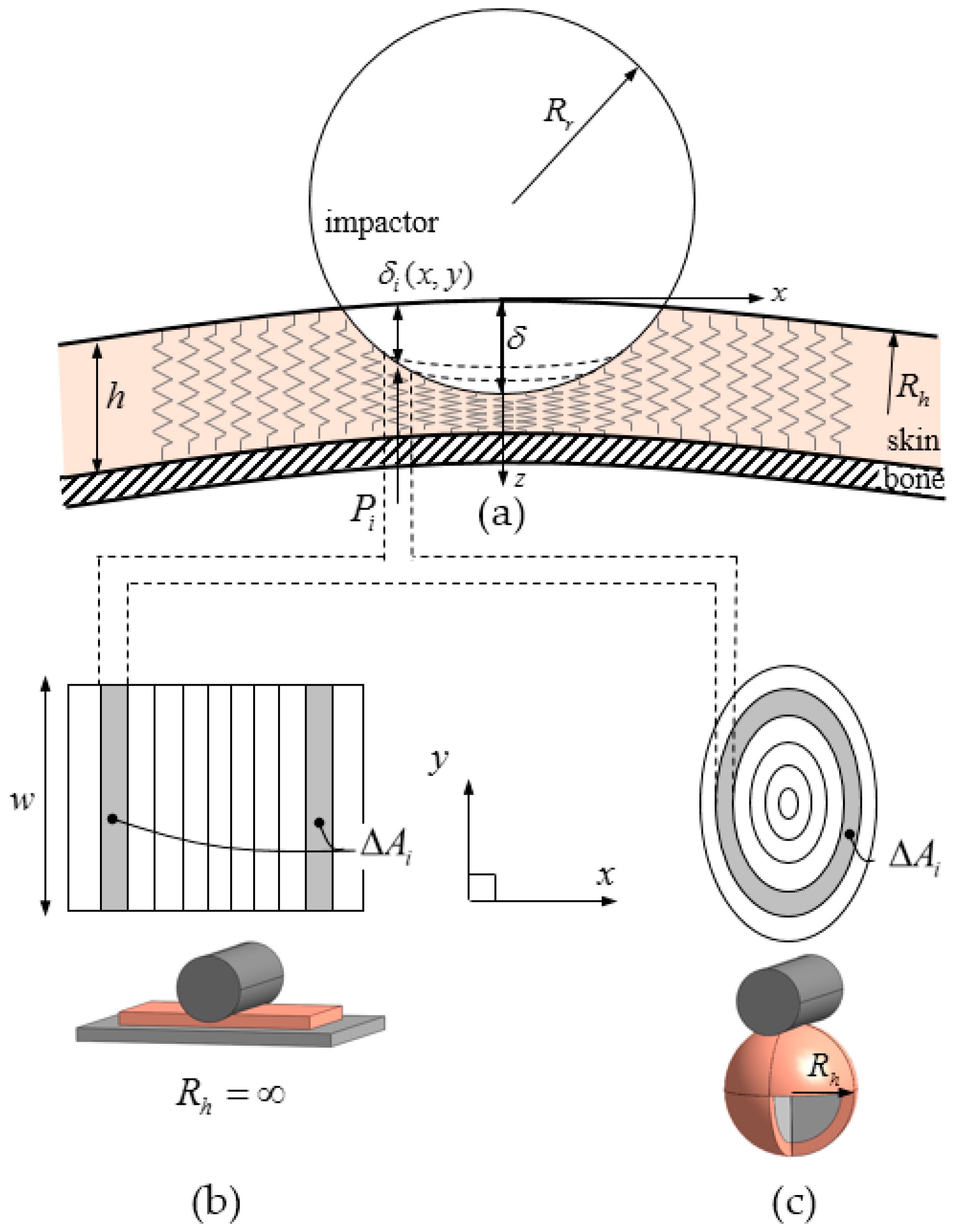
2. Contact Model
2.1. One-layered Nonlinear Contact Model: A Virtual Collision Sensor
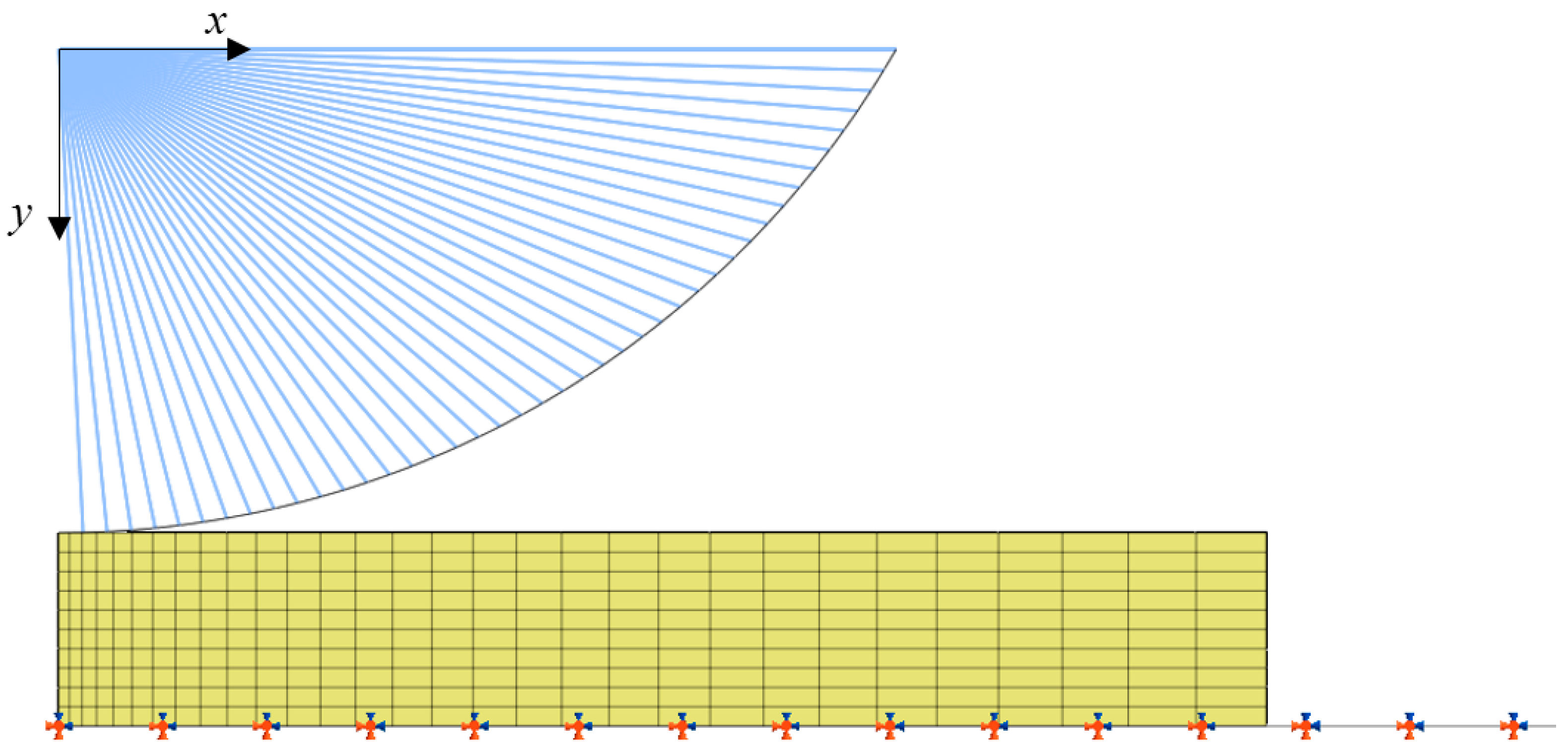
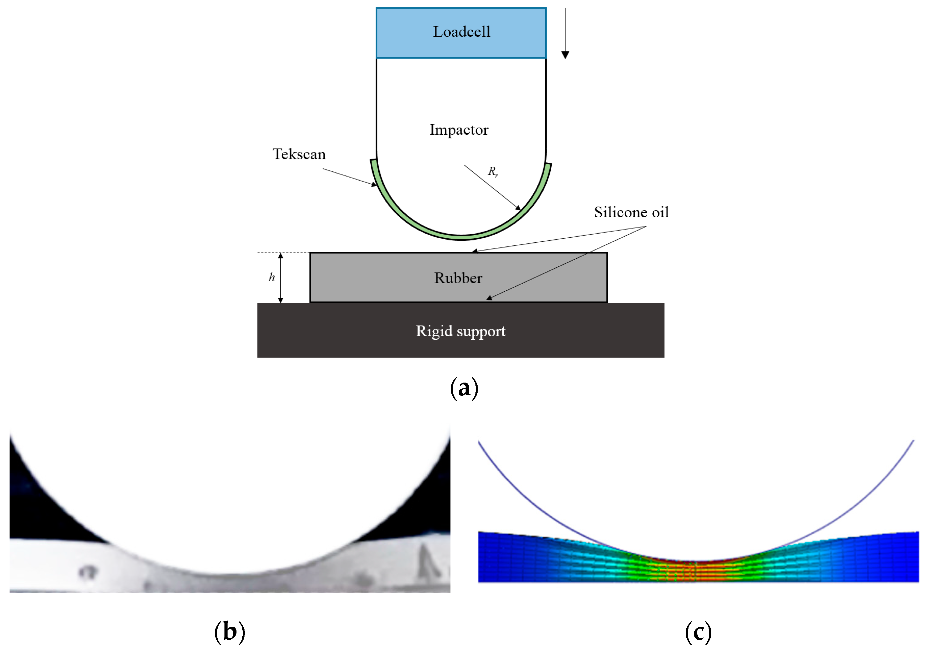
2.2. Finite Element Model
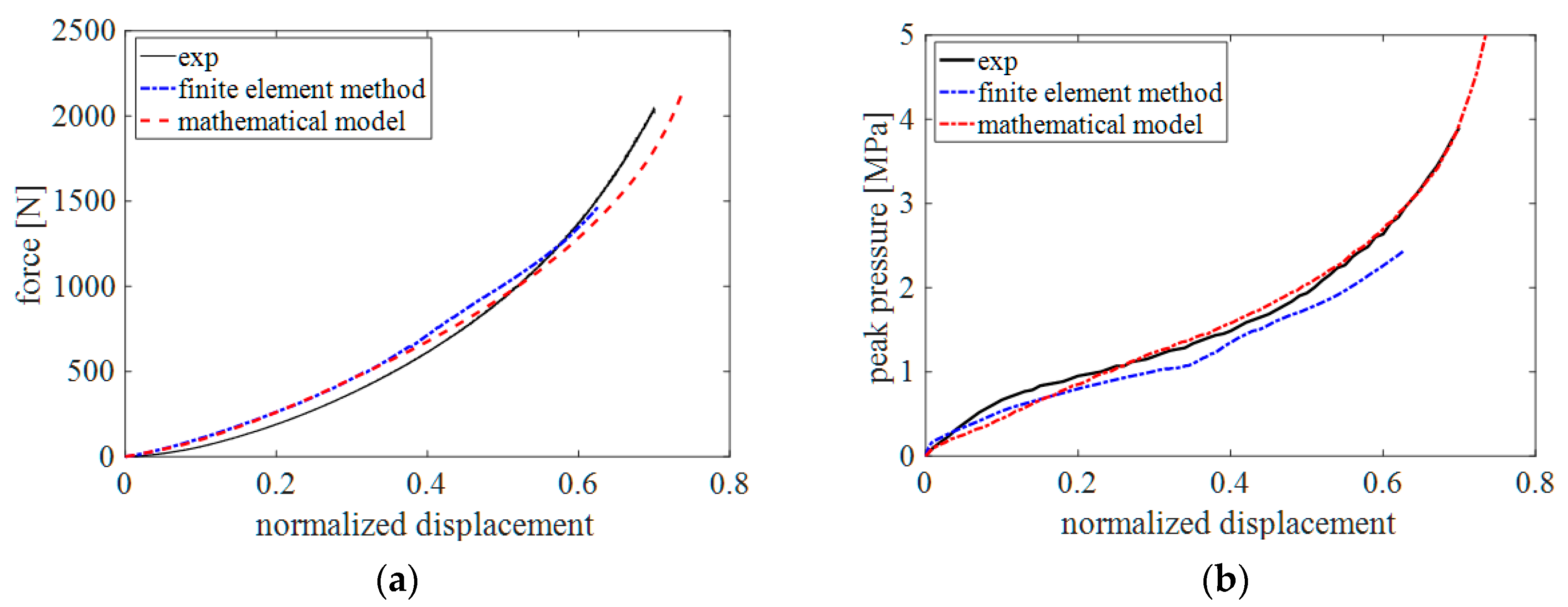
3. Validation of Mathematical Models Comparing with FE Model and Experiment
4. Evaluation of Robot Safety
4.1. Dynamic Modeling of Human–Robot Collisions
4.2. Evaluation of the Robot Collision Safety
5. Conclusions
Author Contributions
Funding
Conflicts of Interest
References
- Su, H.; Sandoval, J.; Vieyres, P.; Poisson, G.; Ferrigno, G.; De Momi, E. Safety-enhanced Collaborative Framework for Tele-operated Minimally Invasive Surgery Using a 7-DoF Torque-controlled Robot. Int. J. Control. Autom. Syst. 2018, 16, 2915–2923. [Google Scholar] [CrossRef]
- Su, H.; Yang, C.; Ferrigno, G.; De Momi, E. Improved Human–Robot Collaborative Control of Redundant Robot for Teleoperated Minimally Invasive Surgery. IEEE Robot. Autom. Lett. 2019, 4, 1447–1453. [Google Scholar] [CrossRef]
- Haddadin, S.; Albu-Schäffer, A.; De Luca, A.; Hirzinger, G. Collision Detection and Reaction: A Contribution to Safe Physical Human-Robot Interaction. In Proceedings of the 2008 IEEE/RSJ International Conference on Intelligent Robots and Systems, Nice, France, 22–26 September 2008; pp. 3356–3363. [Google Scholar]
- Haddadin, S.; De Luca, A.; Albu-Schaffer, A. Robot Collisions: A Survey on Detection, Isolation, and Identification. IEEE Trans. Robot. 2017, 33, 1292–1312. [Google Scholar] [CrossRef]
- De Luca, A.; Mattone, R. Sensorless robot collision detection and hybrid force/motion control. In Proceedings of the 2005 IEEE International Conference on Robotics and Automation, Barcelona, Spain, 18–22 April 2005; pp. 999–1004. [Google Scholar]
- ISO/TS 15066:2016. Robots and Robotic Devices—Collaborative Robots; International Organization for Standardization: Geneva, Switzerland, 2016.
- Shin, H.; Kim, S.; Seo, K.; Rhim, S. A Real-Time Human-Robot Collision Safety Evaluation Method for Collaborative Robot. In Proceedings of the 2019 Third IEEE International Conference on Robotic Computing (IRC), Naples, Italy, 25–27 February 2019; pp. 509–513. [Google Scholar]
- Vemula, B.R.; Ramteen, M.; Spampinato, G.; Fägerström, B. Human-robot impact model: For safety assessment of collaborative robot design. In Proceedings of the 2017 IEEE International Symposium on Robotics and Intelligent Sensors (IRIS), Ottawa, ON, Canada, 5–7 October 2017; pp. 236–242. [Google Scholar]
- Zhang, L.; Yang, K.H.; Dwarampudi, R.; Omori, K.; Li, T.; Chang, K.; Hardy, W.N.; Khalil, T.B.; King, A.I. Recent advances in brain injury research: A new human head model development and validation. In Proceedings of the 45th Stapp Car Crash Conference, San Antonio, TX, USA, 15–17 November 2001; pp. 369–394. [Google Scholar]
- Voo, L.; Kumaresan, S.; Pintar, F.A.; Yoganandan, N.; Sances, A. Finite-element models of the human head. Med Boil. Eng. 1996, 34, 375–381. [Google Scholar] [CrossRef] [PubMed]
- Hertz, H. UÈ ber die BeruÈhrung fester elastischer KoÈrper. J. Reine Angew. Mathematik 1882, 92, 156–171. [Google Scholar]
- Park, J.-J.; Song, J.-B.; Haddadin, S. Collision analysis and safety evaluation using a collision model for the frontal robot–human impact. Robotica 2014, 33, 1536–1550. [Google Scholar] [CrossRef]
- Shin, H.; Choi, J.; Choi, J.; Rhim, S. Physical safety analysis of robot considering impactor shape. In Proceedings of the 2017 2nd International Conference on Robotics and Automation Engineering (ICRAE), Shanghai, China, 29–31 December 2017; pp. 1–5. [Google Scholar]
- Povse, B.; Koritnik, D.; Kamnik, R.; Bajd, T.; Munih, M. Emulation system for assessment of human-robot collision. Meccanica 2011, 46, 1363–1371. [Google Scholar] [CrossRef]
- Haddadin, S.; Haddadin, S.; Khoury, A.; Rokahr, T.; Parusel, S.; Burgkart, R.; Bicchi, A.; Albu-Schäffer, A. On making robots understand safety: Embedding injury knowledge into control. Int. J. Robot. Res. 2012, 31, 1578–1602. [Google Scholar] [CrossRef]
- Collaborative Robot Systems—Design of Systems with “Power and Force Limiting Function” Function; Technical Report FB HM-080; Deutsche Gesetzliche Unfallversicherung (DGUV): Berlin, Germany, 2017.
- Matthias, B.; Oberer-Treitz, S.; Ding, H. Experimental characterization of collaborative robot collisions. In Proceedings of the ISR/Robotik 2014; 41st International Symposium on Robotics, Munich, Germany, 2–3 June 2014; pp. 1–6. [Google Scholar]
- Sneddon, I.N. The relation between load and penetration in the axisymmetric boussinesq problem for a punch of arbitrary profile. Int. J. Eng. Sci. 1965, 3, 47–57. [Google Scholar] [CrossRef]
- Johnson, K.L. Contact Mechanics; Cambridge University Press: Cambridge, UK, 1985. [Google Scholar]
- Taljat, B.; Pharr, G. Development of pile-up during spherical indentation of elastic–plastic solids. Int. J. Solids Struct. 2004, 41, 3891–3904. [Google Scholar] [CrossRef]
- Mendis, K.K.; Stalnaker, R.L.; Advani, S.H. A constitutive relationship for large deformation finite element modeling of brain tissue. Trans. ASME J. Biomech. Eng. 1995, 117, 279–285. [Google Scholar] [CrossRef] [PubMed]
- Khatib, O. Inertial Properties in Robotic Manipulation: An Object-Level Framework. Int. J. Robot. Res. 1995, 14, 19–36. [Google Scholar] [CrossRef]
- OS32C Safety Laser Scanner/Specifications. Available online: http://www.ia.omron.com/products/family/2717/specification.html (accessed on 25 September 2019).
- Wu, J.Z.; Dong, R.G.; Schopper, A.W. Analysis of effects of friction on the deformation behaviour of soft tissues in unconfined compression tests. J. Biomech. 2004, 37, 147–155. [Google Scholar] [CrossRef]
- Size Korea, Korean Agency for Technology and Standards (KATS). Available online: https://sizekorea.kr (accessed on 31 July 2019).
- Hwang, H.S.; Park, M.K.; Lee, W.J.; Cho, J.H.; Kim, B.K.; Wilkinson, C.M. Facial Soft Tissue Thickness Database for Craniofacial Reconstruction in Korean Adults. J. Forensic Sci. 2012, 57, 1442–1447. [Google Scholar] [CrossRef] [PubMed]


© 2019 by the authors. Licensee MDPI, Basel, Switzerland. This article is an open access article distributed under the terms and conditions of the Creative Commons Attribution (CC BY) license (http://creativecommons.org/licenses/by/4.0/).
Share and Cite
Shin, H.; Kim, S.; Seo, K.; Rhim, a.S. A Virtual Pressure and Force Sensor for Safety Evaluation in Collaboration Robot Application. Sensors 2019, 19, 4328. https://doi.org/10.3390/s19194328
Shin H, Kim S, Seo K, Rhim aS. A Virtual Pressure and Force Sensor for Safety Evaluation in Collaboration Robot Application. Sensors. 2019; 19(19):4328. https://doi.org/10.3390/s19194328
Chicago/Turabian StyleShin, Heonseop, Sanghoon Kim, Kwang Seo, and and Sungsoo Rhim. 2019. "A Virtual Pressure and Force Sensor for Safety Evaluation in Collaboration Robot Application" Sensors 19, no. 19: 4328. https://doi.org/10.3390/s19194328
APA StyleShin, H., Kim, S., Seo, K., & Rhim, a. S. (2019). A Virtual Pressure and Force Sensor for Safety Evaluation in Collaboration Robot Application. Sensors, 19(19), 4328. https://doi.org/10.3390/s19194328