A Comprehensive Survey of Recent Routing Protocols for Underwater Acoustic Sensor Networks

Abstract
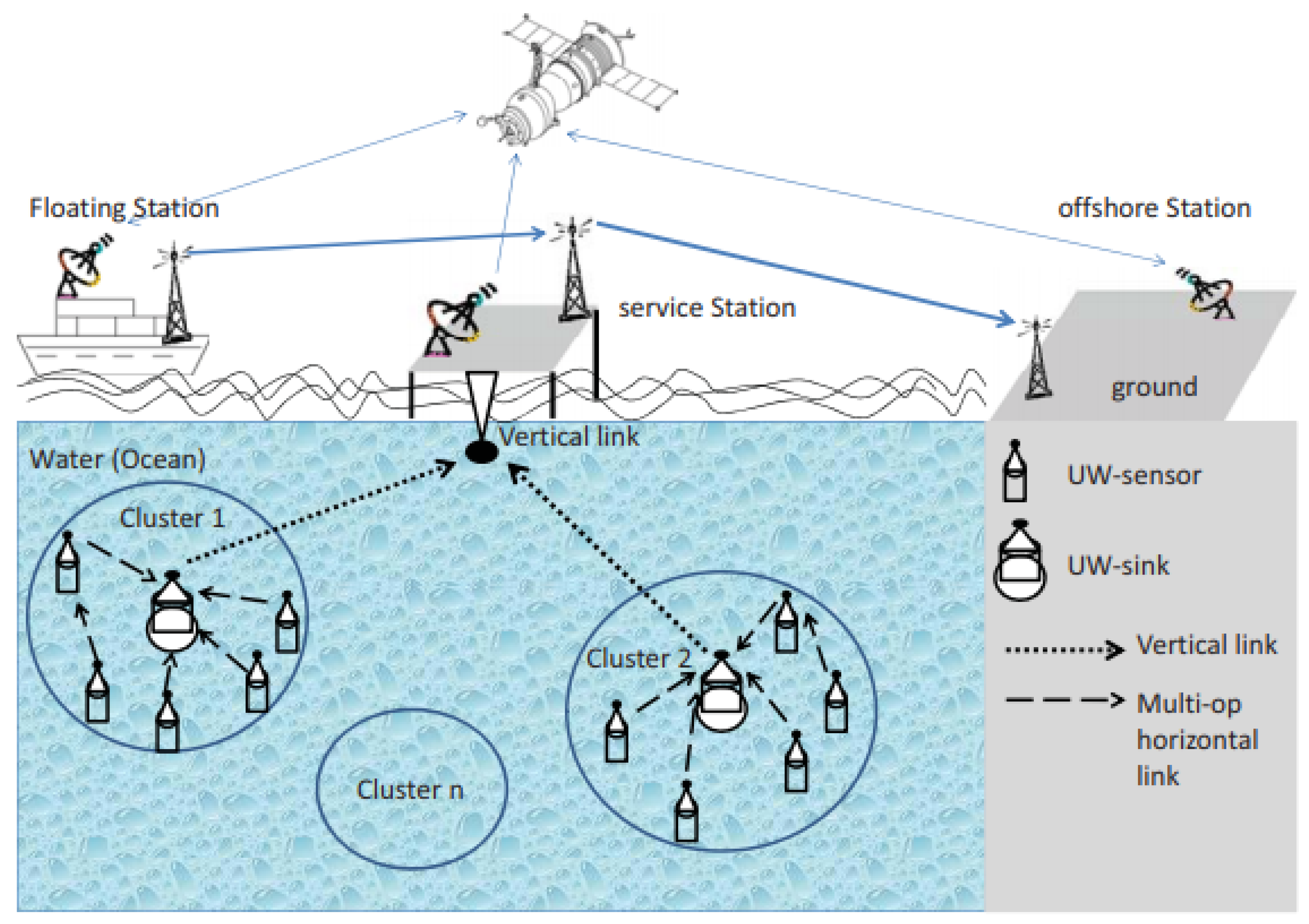
:1. Introduction
2. Characteristics of the Underwater Acoustic Channel
2.1. The Speed of Sound in Water
2.2. Attenuation
2.3. Noise
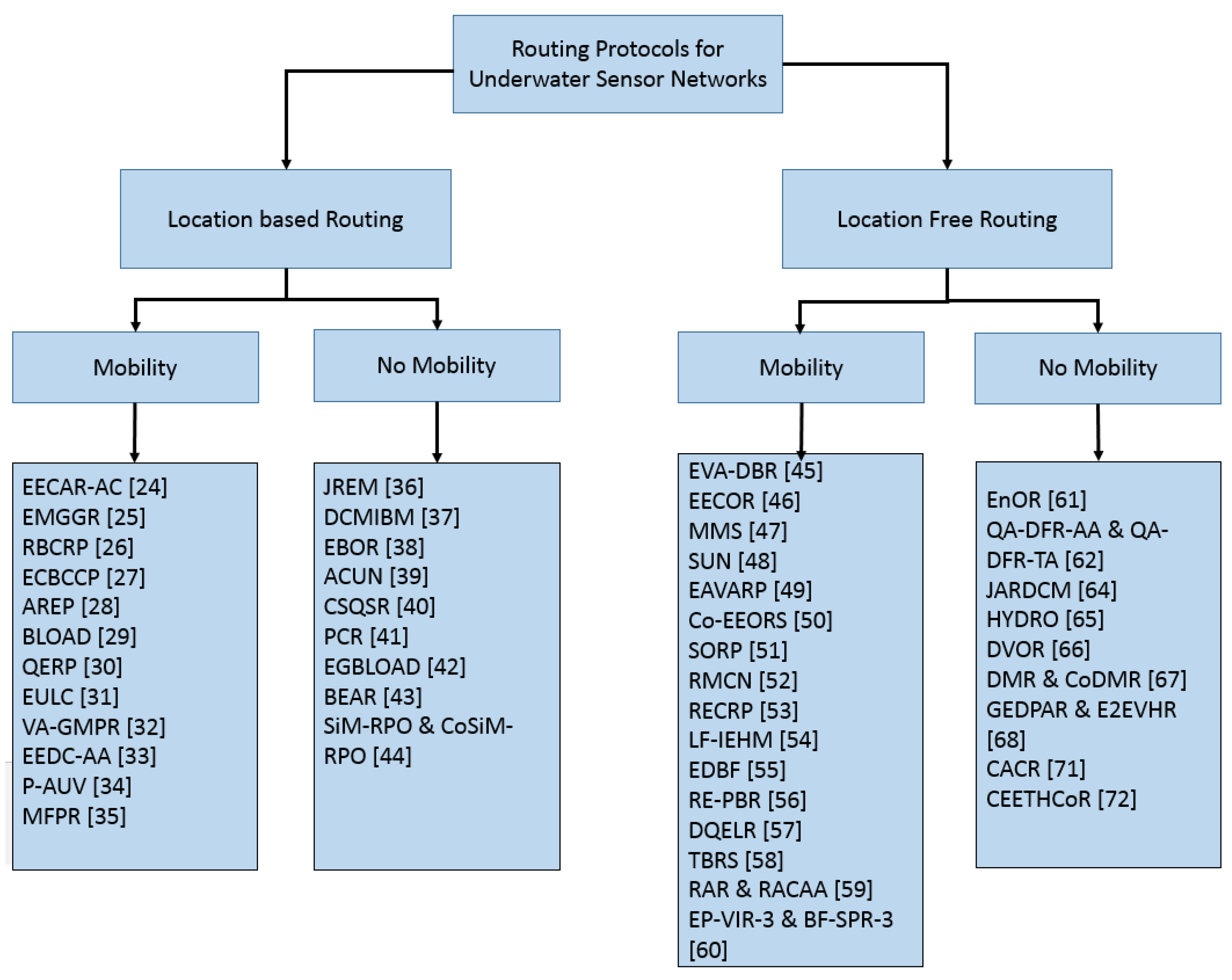
3. Routing Protocols for UWSNs
3.1. Location-Based Routing Schemes
3.1.1. Location-Based Routing with Mobility Consideration
EECAR-AC
EMGGR

| Reference | Main Consideration | Next Hop Selection Criteria | Mobility | Location Required | Clustering | Connectivity Void Handling | Sink | Deployment |
|---|---|---|---|---|---|---|---|---|
| EECAR-AC [24] | Void Avoidance, Network Lifetime, E2E delay. | Node energy, propagation delay, hop count, channel quality | Yes | Yes | Yes | Yes | Multiple Sink | 3D |
| EMGGR [25] | Reliability, Void Avoidance. | Pre-determined multiple node disjoint paths | Yes | Yes | No | Yes | Single-sink (Multi-sink can also be used) | 3D |
| RBCRP [26] | Load Balancing, reduce outage probability of relay nodes. | SNR, depth, residual energy | Yes | Yes | No | No | Multiple Sinks | 3D |
| ECBCCP [27] | Energy conservation, Reliability. | Link quality and hop count | Yes | Yes | Yes | No | Multiple Sinks | 3D |
| AREP [28] | Void handling, Link asymmetry. | Symmetry of link, Distance from the destination | Yes | yes | No | Yes | Single-sink | 3D |
| BLOAD [29] | Energy Holes avoidance, balanced energy consumption. | Distance from sink | Yes | Yes | No | No | Single-sink | 2D |
| QERP [30] | Achieve high packet delivery ratio (PDR), low end-to-end delay, and improve network wide energy consumption for real time applications. | Link quality, shortest path | Yes | Yes | Yes | Yes | Single-sink | 3D |
| EULC [31] | Hot Spot mitigation, Balanced Energy dissipation, Improved network lifetime. | Residual Energy, Distance from the candidate forwarder to the sink node, distance from the current sender to the candidate forwarder | Yes | Yes | Yes | Yes | Single-sink | 3D |
| VA-GMPR [32] | Reliability, Load balancing, void avoidance. | Optimality of Path length | Yes | Yes | No | Yes | Single-sink | 3D |
| EEDC-AA [33] | Balance energy consumption and prolong underwater network lifetime. Prioritize collected data based on its importance. | Available Energy | Yes | Yes | No | No | Multi-sink | 3D |
| P-AUV [34] | Energy efficiency, Low latency. | Distance to the sink node | Yes | Yes | No | No | Multi-sink | 2D |
| MFPR [35] | Identify optimal energy-efficient routing coverage set. | Optimal route selection based on location of nodes and available energy | Yes | Yes | No | No | Multi-sink | 3D |
| JREM [36] | Increase network lifetime by avoiding Energy Holes and balancing energy consumption. | Probability of Successful reception, Load Weights (derived to achieve balanced energy consumption) | No | Yes | No | Yes | Single-sink | 2D |
| DCMIBM [37] | Propose an optimal node placement scheme and a clustering scheme to increase lifetime of the network by controlling energy consumption. | CHs act as relays. CHs are selected based on available energy and location of candidate sensor node within its cluster | No | Yes | Yes | NA | Single-sink | 3D |
| EBOR [38] | Energy consumption, network lifetime Reliability, PDR. | Residual Energy, Packet delivery probability Efficient transmission distance | No | Yes | No | No | Multi-sink | 3D |
| ACUN [39] | Selection of appropriate node as CH based on residual energy distance from sink, Selection of appropriate next hop to minimize energy consumption. | Estimated Energy Consumption of the sender (based on distance from the candidate node) | No | Yes | yes | yes | Single-sink | 3D |
| CSQSR [40] | Guarantee application-specific QoS, while also maximizing the network lifetime. | Node Position/Location Throughput (QoS parameters) | No | Yes | No | No | NA | 3D |
| PCR [41] | Reliable and energy-efficient data delivery using combination of Transmission Power control and opportunistic routing. | Reduction in overall energy cost, Improvement in Packet Delivery Probability | No | Yes | No | Yes | Multi-sink | 3D |
| EGBLOAD [42] | Load balancing, void management. | Available energy and distance of the forwarder from sink | No | Yes | No | Yes | Multi-sink | 3D |
| BEAR [43] | Mitigating imbalanced and inefficient energy consumption. | Residual energy, depth | No | Yes | No | Yes | Single-sink | 2D |
| RPO [44] | Energy Efficiency, Reliability. | NA | No | Yes | No | NA | Multi-sink | 2D |
RBCRP
ECBCCP
AREP
BLOAD
QERP
EULC
VA-GMPR
EEDC-AA
P-AUV
MFPR
3.1.2. Location-Based Routing without Mobility Consideration
JREM
DCMIBM
EBOR
ACUN
CSQSR
PCR
EGBLOAD
BEAR
SiM-RPO & CoSiM-RPO
3.2. Localization-Free Routing Schemes
3.2.1. Localization-Free Routing Schemes with Mobility Consideration
EVA-DBR
EECOR
MMS
SUN
EAVARP
Co-EEORS
SORP
RMCN
RECRP
LF-IEHM
EDBF
RE-PBR
DQELR
TBRS
RAR & RACAA
EP-VIR-3 & BF-SPR-3
3.2.2. Localization-free Routing Schemes without mobility consideration
EnOR
QA DFR AA & QA DFR TA
JARDCM
HYDRO
DVOR
DMR & CoDMR
GEDPAR & E2EVHR
CACR
CEETHCoR
| Ref # | Main Consideration | Next Hop Selection Criteria | Mobility | Location Required | Clustering | Connectivity Void Handling | Sink | Deployment |
|---|---|---|---|---|---|---|---|---|
| EVA-DBR [45] | Detect and bypass the trapped and void nodes in UWSNs. | Depth, distance from the current sender, should not be a void node or trapped node. | Yes | No | No | Yes | Multi-sink | 3D |
| EECOR [46] | Energy Efficiency | Depth, Energy Consumption Ratio (i.e., ratio of the residual and initial energy), Packet delivery probability of the forwarder | Yes | No | No | No | Single-sink | 3D |
| MMS [47] | Energy Efficiency, Packet delivery ratio | Depth/hop count | Yes | No | No | No | Multi-sink | 3D |
| SUN [48] | Improve routing for networks with unreliable links and mobile nodes | Hop count or SNR | Yes | No | No | No | Multi-sink | 3D |
| EAVARP [49] | Balanced load distribution, void avoidance and network lifetime | Transmission capacity (i.e., the node selected as relay should have enough residual energy for transmission, and it should not be a void node) | Yes | No | No | Yes | Multi-sink | 3D |
| Co-EEORS [50] | Reliability, improved Energy efficiency | Depth and location value (location value does not refer to the geographic location of a sensor node, but is measured in terms of a node’s distance from the surface sink node) | yes | No | No | No | Single-sink | 3D |
| SORP [51] | Void Handling | Depth, the node in question should not be a void or trapped node, and it should be located in the forwarding area | Yes | No | No | Yes | Multi-sink | 3D |
| RMCN [52] | Facilitate network operations for longer periods in risky areas | Residual Energy Distance between Sender and candidate forwarder depth | Yes | No | No | No | Multi-sink | 3D |
| RECRP [53] | Reduce and balance Energy consumption | Node Level (min hop count to sink), Distance between the sender and the forwarder, Residual Energy | Yes | No | No | Yes | Multi-sink | 3D |
| LF-IEHM [54] | Void management and interference mitigation | Pressure level (depth) Response time (a function of mainly Distance between sender and the candidate forwarder) | yes | No | No | Yes | Single-sink | 3D |
| EDBF [55] | Load Balancing, Void Avoidance | Residual energy, depth, and historical forwarding conditions | Yes | No | No | Yes | Multi-sink | 3D |
| RE-PBR [56] | End-to-end delivery, Reliability, load balancing | Depth, Residual Energy, Link Quality | Yes | No | No | No | Multi-sink | 3D |
| DQELR [57] | Prolong network lifetime | Q value (which is based on Residual energy, depth) | Yes | No | No | No | Single-sink | 3D |
| TBRS [58] | Energy Sink hole problem, load balancing, prolong network lifetime | NA | Yes | No | No | Yes | Single-sink | 2D |
| RAR & RACAA [59] | Reliable end-to-end routing | Predetermined paths selected based on highest probability of success, which is a function of path connectivity and channel conditions | Yes | No | No | No | Single-sink | 3D |
| EP-VIR-3 & BF-SPR-3 [60] | Energy efficiency, interference-free transmission, void hole avoidance, and high Packet Delivery Ratio | Distance from the sender, hop count from sink, minimum no. of neighbors of forwarder node | Yes | No | No | Yes | Multi-sink | 3D |
| EnOR [61] | Extend the network lifetime | Residual Energy, link reliability, depth | No | No | No | No | Multi-sink | 3D |
| QA-DFR-AA & QA-DFR-TA [62] | QoS aware Routing, avoid packet collision and redundant packet transmission | NA | No | No | No | No | Single-sink | 2D |
| JARDCM [64] | Energy Efficiency, Reliable data delivery | Residual Energy, Depth, Packet advancement, delay | No | No | No | No | Multi-sink | 3D |
| HYDRO [65] | Increased network lifetime by exploiting energy harvesting. Improve energy efficiency, latency and PDR. | Residual energy and foreseeable harvestable energy channel quality and a measure of energy availability through the whole route to the sink | No | No | No | No | Single-sink | 3D |
| DVOR [66] | Solving Void and long detour problems | Hop count to sink | No | No | No | Yes | Multi-sink | 3D |
| DMR & CoDMR [67] | Delay minimization | Distance to the sink node | No | No | No | No | Multi-sink | 3D |
| GEDPAR & E2EVHR [68] | Void elimination and network lifetime | Energy consumption | No | No | No | Yes | Multi-sink | 3D |
| CACR [71] | Reliable data delivery | Link quality and hop count to destination | No | No | No | No | Single-sink | 3D |
| CEETHCoR [72] | Energy Efficiency, Reliability | Link Quality, hop count, Residual Energy | No | No | No | No | Single-sink | 3D |
4. Conclusions
5. Future Work and Challenges
Funding
Conflicts of Interest
References
- Tan, H.P.; Diamant, R.; Seah, W.K.; Waldmeyer, M. A survey of techniques and challenges in underwater localization. Ocean Eng. 2011, 38, 1663–1676. [Google Scholar] [CrossRef] [Green Version]
- Lin, W.; Li, D.; Tan, Y.; Chen, J.; Sun, T. Architecture of underwater acoustic sensor networks: A survey. In Proceedings of the 2008 First International Conference on Intelligent Networks and Intelligent Systems, Wuhan, China, 1–3 November 2008; pp. 155–159. [Google Scholar]
- Akyildiz, I.F.; Pompili, D.; Melodia, T. Underwater acoustic sensor networks: Research challenges. Ad Hoc Netw. 2005, 3, 257–279. [Google Scholar] [CrossRef]
- Manjula, R.B.; Sunilkumar, S.M. Issues in underwater acoustic sensor networks. Int. J. Comput. Electr. Eng. 2011, 3, 101. [Google Scholar]
- Kao, C.; Lin, Y.; Wu, G.; Huang, C. A comprehensive study on the internet of underwater things: Applications, challenges, and channel models. Sensors 2017, 17, 1477. [Google Scholar] [CrossRef] [PubMed]
- Li, N.; Martinez, J.F.; Chaus, J.M.M.; Eckert, M. A survey on underwater acoustic sensor network routing protocols. Sensors 2016, 16, 414. [Google Scholar] [CrossRef] [PubMed]
- Anwar, A.; Sridharan, D. A survey on routing protocols for wireless sensor networks in various environments. Int. J. Comput. Appl. 2015, 112, 13–29. [Google Scholar]
- Han, G.; Jiang, J.; Bao, N.; Guizani, M. Routing protocols for underwater wireless sensor networks. IEEE Commun. Mag. 2015, 53, 72–78. [Google Scholar] [CrossRef]
- Coutinho, R.W.L.; Boukerche, A.; Vieira, L.F.M.; Loureiro, A.A.F. Underwater wireless sensor networks: A new challenge for topology control-based systems. ACM Comput. Surv. 2018, 51, 19–34. [Google Scholar] [CrossRef]
- Khalil, I.M.; Gadallah, Y.; Hayajneh, M.; Khreishah, A. An adaptive OFDMA-based MAC protocol for underwater acoustic wireless sensor networks. Sensors 2012, 12, 8782–8805. [Google Scholar] [CrossRef]
- Chang, S.; Li, Y.; He, Y.; Wang, H. Target localization in underwater acoustic sensor networks using RSS measurements. Appl. Sci. 2018, 8, 225. [Google Scholar] [CrossRef]
- Islam, T.; Lee, Y.K. A Cluster Based Localization Scheme with Partition Handling for Mobile Underwater Acoustic Sensor Networks. Sensors 2019, 19, 1039. [Google Scholar] [CrossRef] [PubMed]
- Islam, T.; Lee, Y.K. A Two-Stage Localization Scheme with Partition Handling for Data Tagging in Underwater Acoustic Sensor Networks. Sensors 2019, 19, 2135. [Google Scholar] [CrossRef] [PubMed]
- Zhou, Z.; Peng, Z.; Cui, J.H.; Shi, Z.; Bagtzoglou, A. Scalable localization with mobility prediction for underwater sensor networks. IEEE Trans. Mob. Comput. 2011, 10, 335–348. [Google Scholar] [CrossRef]
- Luo, J.; Fan, L. A Two-Phase time synchronization-free localization algorithm for underwater sensor networks. Sensors 2017, 17, 726. [Google Scholar] [CrossRef] [PubMed]
- Moradi, M.; Rezazadeh, J.; Ismail, A.S. A reverse localization scheme for underwater acoustic sensor networks. Sensors 2012, 12, 4352–4380. [Google Scholar] [CrossRef] [PubMed]
- Cheng, X.; Shu, H.; Liang, Q.; Du, D.H.C. Silent positioning in underwater acoustic sensor networks. IEEE Trans. Veh. Technol. 2008, 57, 1756–1766. [Google Scholar] [CrossRef]
- Luo, H.; Guo, Z.; Dong, W.; Hong, F.; Zhao, Y. LDB: Localization with directional beacons for sparse 3D underwater acoustic sensor networks. J. Netw. 2010, 5. [Google Scholar] [CrossRef]
- Luo, H.; Zhao, Y.; Guo, Z.; Liu, S.; Chen, P.; Ni, L.M. UDB: Using directional beacons for localization in underwater sensor networks. In Proceedings of the 2008 14th IEEE International Conference on Parallel and Distributed Systems, Melbourne, VIC, Australia, 8–10 December 2008. [Google Scholar]
- Munafò, A.; Ferri, G. An acoustic network navigation system. J. Field Robot. 2017, 34, 1332–1351. [Google Scholar] [CrossRef]
- Reed, M.S. Use of an Acoustic Network as an Underwater Positioning System; Naval Postgraduate School: Monterey, CA, USA, 2006. [Google Scholar]
- Szlachetko, B.; Lower, M. Smart Underwater Positioning System and Simultaneous Communication. In International Conference on Computational Collective Intelligence; Springer: Cham, Switzerland, 2016; pp. 158–167. [Google Scholar]
- Vakulya, G.; Simon, G. Efficient sensor network based acoustic localization. In Proceedings of the 2011 IEEE International Instrumentation and Measurement Technology Conference, Hangzhou, China, 10–12 May 2011; pp. 1–5. [Google Scholar]
- Bharamagoudra, M.R.; Manvi, S.S.; Gonen, B. Event driven energy depth and channel aware routing for underwater acoustic sensor networks: Agent oriented clustering based approach. Comput. Electr. Eng. 2017, 58, 1–19. [Google Scholar] [CrossRef]
- Al Salti, F.; Alzeidi, N.; Arafeh, B.R. EMGGR: An energy-efficient multipath grid-based geographic routing protocol for underwater wireless sensor networks. Wirel. Netw. 2017, 23, 1301–1314. [Google Scholar] [CrossRef]
- Javaid, N.; Hussain, S.; Ahmad, A.; Imran, M.; Khan, A.; Guizani, M. Region based cooperative routing in underwater wireless sensor networks. J. Netw. Comput. Appl. 2017, 92, 31–41. [Google Scholar] [CrossRef]
- Rani, S.; Ahmed, S.H.; Malhotra, J.; Talwar, R. Energy efficient chain based routing protocol for underwater wireless sensor networks. J. Netw. Comput. Appl. 2017, 92, 42–50. [Google Scholar] [CrossRef]
- Han, G.; Liu, L.; Bao, N.; Jiang, J.; Zhang, W.; Rodrigues, J.J.P.C. Arep: An asymmetric link-based reverse routing protocol for underwater acoustic sensor networks. J. Netw. Comput. Appl. 2017, 92, 51–58. [Google Scholar] [CrossRef]
- Azam, I.; Javaid, N.; Ahmad, A.; Abdul, W.; Almogren, A.; Alamri, A. Balanced load distribution with energy hole avoidance in underwater WSNs. IEEE Access 2017, 5, 15206–15221. [Google Scholar] [CrossRef]
- Muhammad, F.; Tuna, G.; Gungor, V.C. QERP: Quality-of-service (QoS) aware evolutionary routing protocol for underwater wireless sensor networks. IEEE Syst. J. 2018, 12, 2066–2073. [Google Scholar]
- Hou, R.; He, L.; Hu, S.; Luo, J. Energy-balanced unequal layering clustering in underwater acoustic sensor networks. IEEE Access 2018, 6, 39685–39691. [Google Scholar] [CrossRef]
- Al-Subhi, T.; Arafeh, B.; Alzeidi, N.; Day, K.; Touzene, A. A Void Avoidance Scheme for Grid-Based Multipath Routing in Underwater Wireless Sensor Networks. Wirel. Sens. Netw. 2018, 10, 131. [Google Scholar] [CrossRef]
- Jing, Y.; Yang, X.; Luo, X.; Chen, C. Energy-efficient data collection over AUV-assisted underwater acoustic sensor network. IEEE Syst. J. 2018, 99, 1–12. [Google Scholar]
- Bereketli, A.; Tümçakır, M.; Yeni, B. P-AUV: Position aware routing and medium access for ad hoc AUV networks. J. Netw. Comput. Appl. 2019, 125, 146–154. [Google Scholar] [CrossRef]
- Sivakumar, V.; Rekha, D. A QoS-aware energy-efficient memetic flower pollination routing protocol for underwater acoustic sensor network. Concurr. Comput. Pract. Exp. 2019, e5166. [Google Scholar] [CrossRef]
- Fatma, B.; Zidi, C.; Boutaba, R. Joint routing and energy management in underwater acoustic sensor networks. IEEE Trans. Netw. Serv. Manag. 2017, 14, 456–471. [Google Scholar]
- Sai, W.; Nguyen, T.L.N.; Shin, Y. Data collection strategy for magnetic induction based monitoring in underwater sensor networks. IEEE Access 2018, 6, 43644–43653. [Google Scholar]
- Jin, Z.; Ji, Z.; Su, Y. An Evidence Theory Based Opportunistic Routing Protocol for Underwater Acoustic Sensor Networks. IEEE Access 2018, 6, 71038–71047. [Google Scholar] [CrossRef]
- Wan, Z.; Liu, S.; Ni, W.; Xu, Z. An energy-efficient multi-level adaptive clustering routing algorithm for underwater wireless sensor networks. Clust. Comput. 2018, 1–10. [Google Scholar] [CrossRef]
- Emokpae, L.E.; Liu, Z.; Edelmann, G.F.; Younis, M. A Cross-Stack QoS Routing Approach for Underwater Acoustic Sensor Networks. In Proceedings of the 2018 Fourth Underwater Communications and Networking Conference (UComms), Lerici, Italy, 28–30 August 2018; pp. 1–5. [Google Scholar]
- Coutinho, R.W.L.; Boukerche, A.; Loureiro, A.A.F. PCR: A Power Control-based Opportunistic Routing for Underwater Sensor Networks. In Proceedings of the 21st ACM International Conference on Modeling, Analysis and Simulation of Wireless and Mobile Systems, Montreal, QC, Canada, 28 October–2 November 2018; pp. 173–180. [Google Scholar]
- Khan, Z.A.; Latif, G.; Sher, A.; Usman, I.; Ashraf, M.; Ilahi, M.; Javaid, N. Efficient routing for corona based underwater wireless sensor networks. Computing 2019, 101, 831–856. [Google Scholar] [CrossRef]
- Javaid, N.; Cheema, S.; Akbar, M.; Alrajeh, N.; Alabed, M.S.; Guizani, N. Balanced energy consumption based adaptive routing for IoT enabling underwater WSNs. IEEE Access 2017, 5, 10040–10051. [Google Scholar] [CrossRef]
- Ali, M.; Khan, A.; Aurangzeb, K.; Ali, I.; Mahmood, H.; Haider, S.I.; Bhatti, N. CoSiM-RPO: Cooperative Routing with Sink Mobility for Reliable and Persistent Operation in Underwater Acoustic Wireless Sensor Networks. Sensors 2019, 19, 1101. [Google Scholar] [CrossRef]
- Toso, G.; Masiero, R.; Casari, P.; Komar, M.; Kebkal, O.; Zorzi, M. Revisiting Source Routing for Underwater Networking: The SUN Protocol. IEEE Access 2018, 6, 1525–1541. [Google Scholar] [CrossRef]
- Ghoreyshi, S.M.; Shahrabi, l.; Boutaleb, T. An underwater routing protocol with void detection and bypassing capability. In Proceedings of the 2017 IEEE 31st International Conference on Advanced Information Networking and Applications (AINA), Taipei, Taiwan, 27–29 March 2017; pp. 530–537. [Google Scholar]
- Rahman, M.A.; Lee, Y.; Koo, I. EECOR: An energy-efficient cooperative opportunistic routing protocol for Underwater acoustic sensor networks. IEEE Access 2017, 5, 14119–14132. [Google Scholar] [CrossRef]
- Wang, Z.; Sui, Y.; Feng, X.; Liu, J. Mobile-MultiSink Routing Protocol for Underwater Wireless Sensor Networks. Int. J. Perform. Eng. 2017, 13, 966–974. [Google Scholar] [CrossRef]
- Zhuo, W.; Han, G.; Qin, H.; Zhang, S.; Sui, Y. An energy-aware and void-avoidable routing protocol for underwater sensor networks. IEEE Access 2018, 6, 7792–7801. [Google Scholar]
- Anwar, K.; Ali, I.; Rahman, A.U.; Imran, M.; Mahmood, H. Co-EEORS: Cooperative energy efficient optimal relay selection protocol for underwater wireless sensor networks. IEEE Access 2018, 6, 28777–28789. [Google Scholar]
- Ghoreyshi, S.M.; Shahrabi, A.; Boutaleb, T. A Stateless Opportunistic Routing Protocol for Underwater Sensor Networks. Wirel. Commun. Mob. Comput. 2018, 2018, 8237351. [Google Scholar] [CrossRef]
- Khalid, M.; Cao, Y.; Ahmad, N.; Khalid, W.; Dhawankar, P. Radius-based multipath courier node routing protocol for acoustic communications. IET Wirel. Sens. Syst. 2018, 8, 183–189. [Google Scholar] [CrossRef]
- Liu, J.; Yu, M.; Wang, X.; Liu, Y.; Wei, X.; Cui, J. RECRP: An Underwater Reliable Energy-Efficient Cross-Layer Routing Protocol. Sensors 2018, 18, 4148. [Google Scholar] [CrossRef] [PubMed]
- Khan, A.; Ahmedy, I.; Anisi, M.; Javaid, N.; Ali, I.; Khan, N.; Alsaqer, M.; Mahmood, H. A localization-free interference and energy holes minimization routing for underwater wireless sensor networks. Sensors 2018, 18, 165. [Google Scholar] [CrossRef] [PubMed]
- Liu, X.; Liu, P.; Long, T.; Lv, Z.; Tang, R. An efficient depth-based forwarding protocol for underwater wireless sensor networks. In Proceedings of the 2018 IEEE 3rd International Conference on Cloud Computing and Big Data Analysis (ICCCBDA), Chengdu, China, 20–22 April 2018; pp. 467–475. [Google Scholar]
- Khasawneh, A.; Latiff, M.S.B.A.; Kaiwartya, O.; Chizari, H. A reliable energy-efficient pressure-based routing protocol for underwater wireless sensor network. Wirel. Netw. 2018, 24, 2061–2075. [Google Scholar] [CrossRef]
- Su, Y.; Fan, R.; Fu, X.; Jin, Z. DQELR: An Adaptive Deep Q-Network-Based Energy-and Latency-Aware Routing Protocol Design for Underwater Acoustic Sensor Networks. IEEE Access 2019, 7, 9091–9104. [Google Scholar] [CrossRef]
- Albukhary, R.A.; Bouabdallah, F. Time-variant balanced routing strategy for underwater wireless sensor networks. Wirel. Netw. 2019, 25, 3481–3495. [Google Scholar] [CrossRef]
- Khan, A.; Altowaijri, S.M.; Ali, I.; Rahman, A.U. Reliability-Aware Cooperative Routing with Adaptive Amplification for Underwater Acoustic Wireless Sensor Networks. Symmetry 2019, 11, 421. [Google Scholar] [CrossRef]
- Awais, M.; Javaid, N.; Rehman, A.; Qasim, U.; Alhussein, M.; Aurangzeb, K. Towards Void Hole Alleviation by Exploiting the Energy Efficient Path and by Providing the Interference-Free Proactive Routing Protocols in IoT Enabled Underwater WSNs. Sensors 2019, 19, 1313. [Google Scholar] [CrossRef] [PubMed]
- Coutinho, R.W.L.; Boukerche, A.; Vieira, L.; Loureiro, A. EnOR: Energy balancing routing protocol for underwater sensor networks. In Proceedings of the 2017 IEEE International Conference on Communications (ICC), Paris, France, 21–25 May 2017; pp. 1–6. [Google Scholar]
- Ahmed, S.H.; Lee, S.; Park, J.; Kim, D.; Rawat, D.B. iDFR: Intelligent directional flooding-based routing protocols for underwater sensor networks. In Proceedings of the 2017 14th IEEE Annual Consumer Communications & Networking Conference (CCNC), Las Vegas, NV, USA, 8–11 January 2017; pp. 560–565. [Google Scholar]
- Hwang, D.; Kim, D. DFR: Directional flooding-based routing protocol for underwater sensor networks. In Proceedings of the OCEANS 2008, Quebec City, QC, Canada, 15–18 September 2008; pp. 1–7. [Google Scholar]
- Coutinho, R.; Boukerche, A.; Vieira, L.F.M.; Loureiro, A.A. A Joint Anypath Routing and Duty-Cycling Model for Sustainable Underwater Sensor Networks. IEEE Trans. Sustain. Comput. 2018, 1. [Google Scholar] [CrossRef]
- Basagni, S.; di Valerio, V.; Gjanci, P.; Petrioli, C. Harnessing hydro: Harvesting-aware data routing for underwater wireless sensor networks. In Proceedings of the Eighteenth ACM International Symposium on Mobile Ad Hoc Networking and Computing, Chennai, India, 10–14 July 2017; pp. 271–279. [Google Scholar]
- Guan, Q.; Ji, F.; Liu, Y.; Yu, H.; Chen, W. Distance-Vector based Opportunistic Routing for Underwater Acoustic Sensor Networks. IEEE Internet Things J. 2019, 6, 3831–3839. [Google Scholar] [CrossRef]
- Ullah, U.; Khan, A.; Altowaijri, S.M.; Ali, I.; Rahman, A.U.; Kumar, V.; Ali, M.; Mahmood, H. Cooperative and Delay Minimization Routing Schemes for Dense Underwater Wireless Sensor Networks. Symmetry 2019, 11, 195. [Google Scholar] [CrossRef]
- Mateen, A.; Awais, M.; Javaid, N.; Ishmanov, F.; Afzal, M.K.; Kazmi, S. Geographic and Opportunistic Recovery with Depth and Power Transmission Adjustment for Energy-Efficiency and Void Hole Alleviation in UWSNs. Sensors 2019, 19, 709. [Google Scholar] [CrossRef] [PubMed]
- Coutinho, R.W.L.; Boukerche, A.; Vieira, L.F.M.; Loureiro, A.A.F. GEDAR: Geographic and opportunistic routing protocol with depth adjustment for mobile underwater sensor networks. In Proceedings of the 2014 IEEE International Conference on Communications (ICC), Sydney, NSW, Australia, 10–14 June 2014; pp. 251–256. [Google Scholar]
- Xu, J.; Li, K.; Min, G. Layered multi-path power control in underwater sensor networks. In Proceedings of the 2010 IEEE Global Telecommunications Conference GLOBECOM 2010, Miami, FL, USA, 6–10 December 2010; pp. 1–5. [Google Scholar]
- Tran-Dang, H.; Kim, D. Channel-aware cooperative routing in underwater acoustic sensor networks. J. Commun. Netw. 2019, 21, 33–44. [Google Scholar] [CrossRef]
- Tran-Dang, H.; Kim, D.S. Channel-Aware Energy-Efficient Two-Hop Cooperative Routing Protocol for Underwater Acoustic Sensor Networks. IEEE Access 2019, 7, 63181–63194. [Google Scholar] [CrossRef]


© 2019 by the authors. Licensee MDPI, Basel, Switzerland. This article is an open access article distributed under the terms and conditions of the Creative Commons Attribution (CC BY) license (http://creativecommons.org/licenses/by/4.0/).
Share and Cite
Islam, T.; Lee, Y.K. A Comprehensive Survey of Recent Routing Protocols for Underwater Acoustic Sensor Networks. Sensors 2019, 19, 4256. https://doi.org/10.3390/s19194256
Islam T, Lee YK. A Comprehensive Survey of Recent Routing Protocols for Underwater Acoustic Sensor Networks. Sensors. 2019; 19(19):4256. https://doi.org/10.3390/s19194256
Chicago/Turabian StyleIslam, Tariq, and Yong Kyu Lee. 2019. "A Comprehensive Survey of Recent Routing Protocols for Underwater Acoustic Sensor Networks" Sensors 19, no. 19: 4256. https://doi.org/10.3390/s19194256
APA StyleIslam, T., & Lee, Y. K. (2019). A Comprehensive Survey of Recent Routing Protocols for Underwater Acoustic Sensor Networks. Sensors, 19(19), 4256. https://doi.org/10.3390/s19194256