Testing of a MEMS Dynamic Inclinometer Using the Stewart Platform

Abstract
:1. Introduction
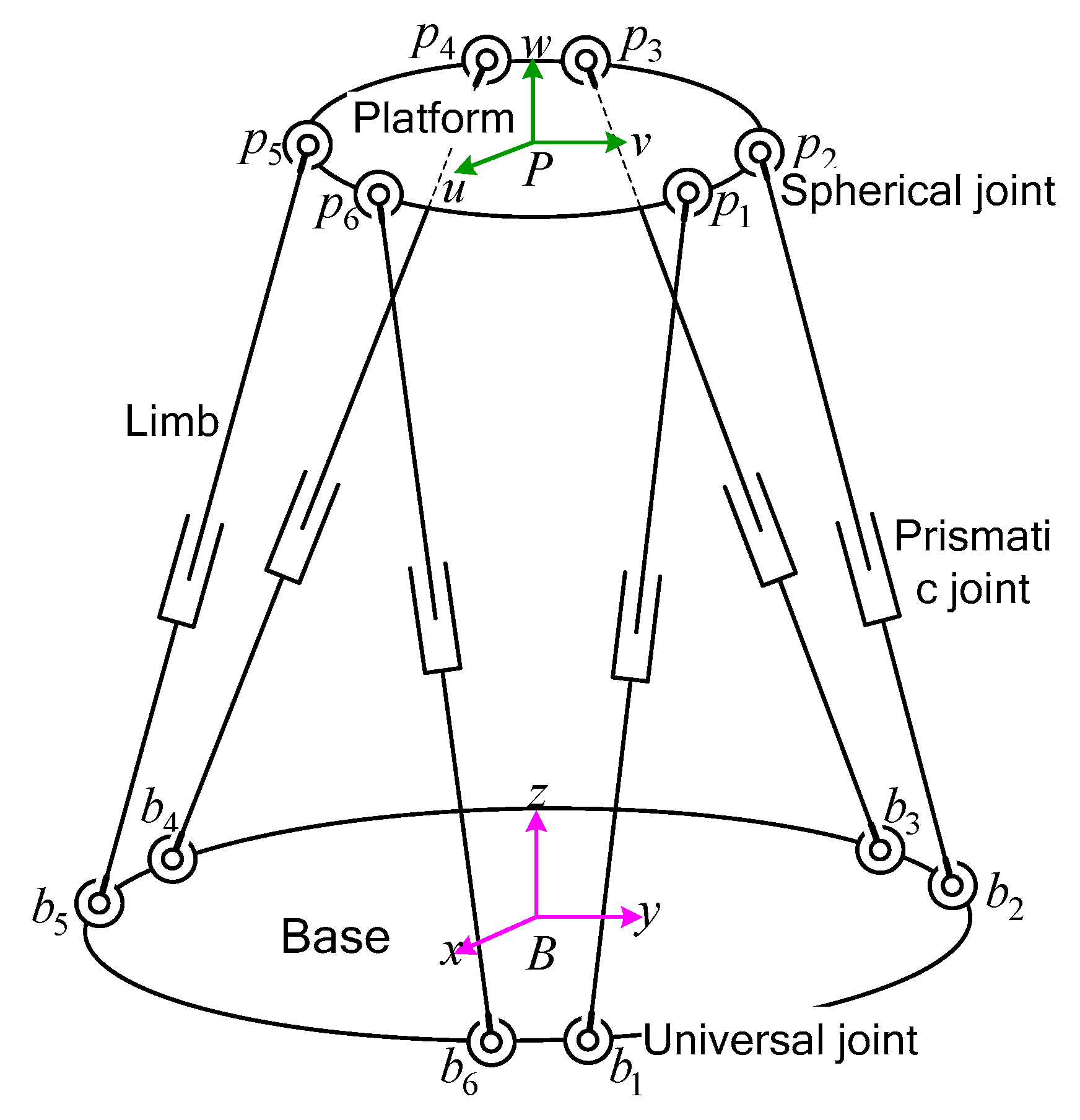
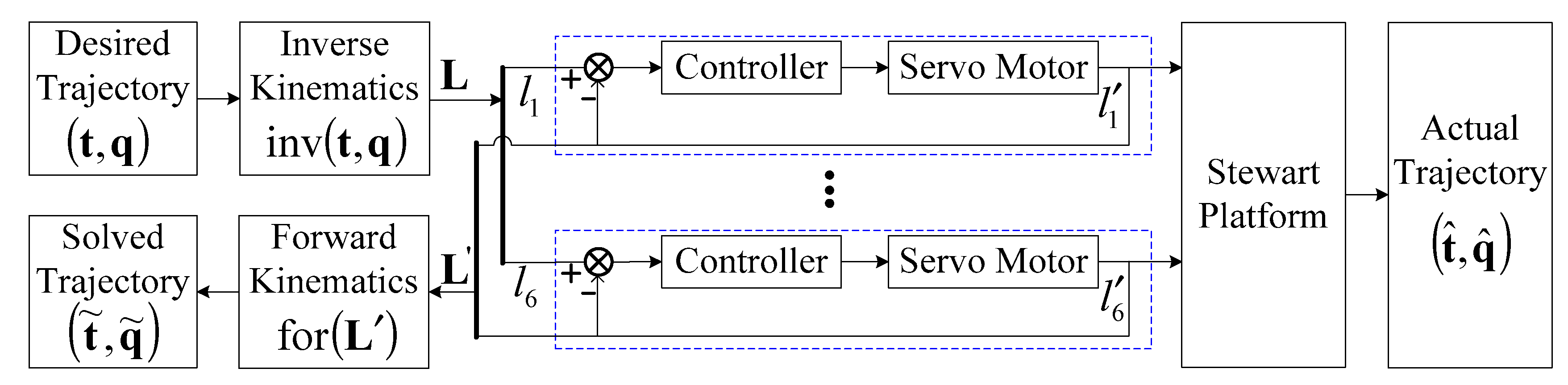
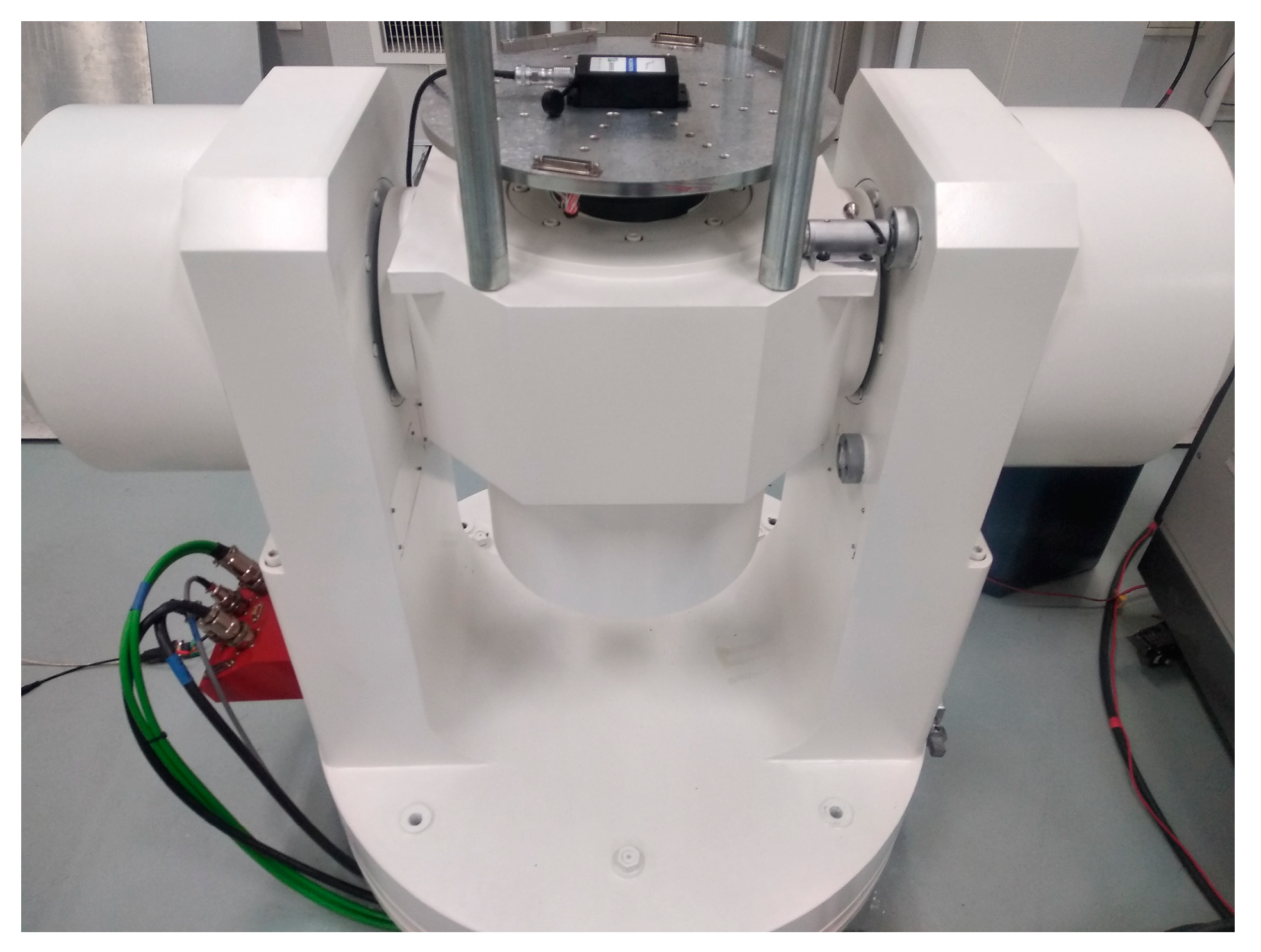
2. Stewart Platform
2.1. Kinematic Analysis
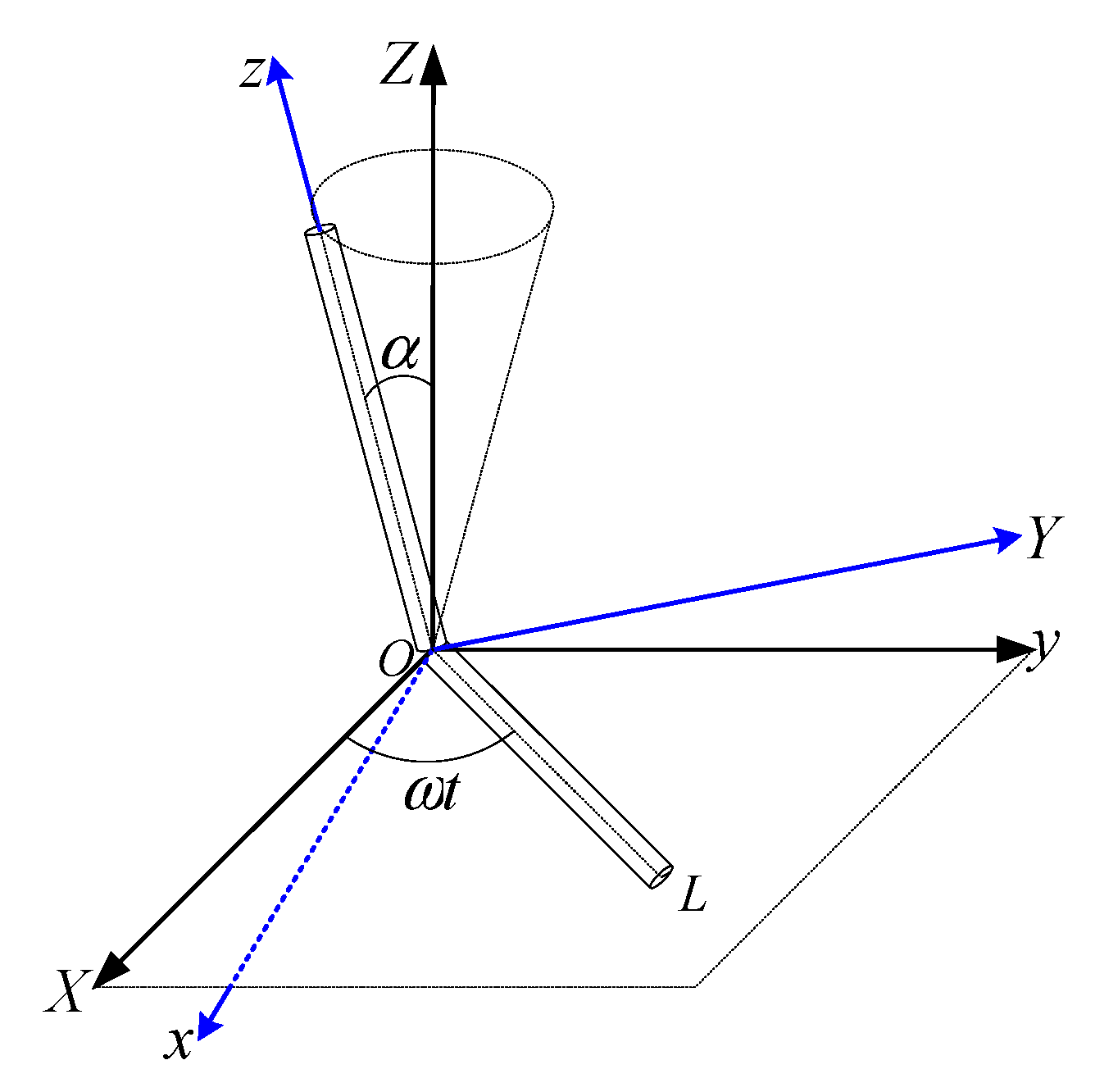
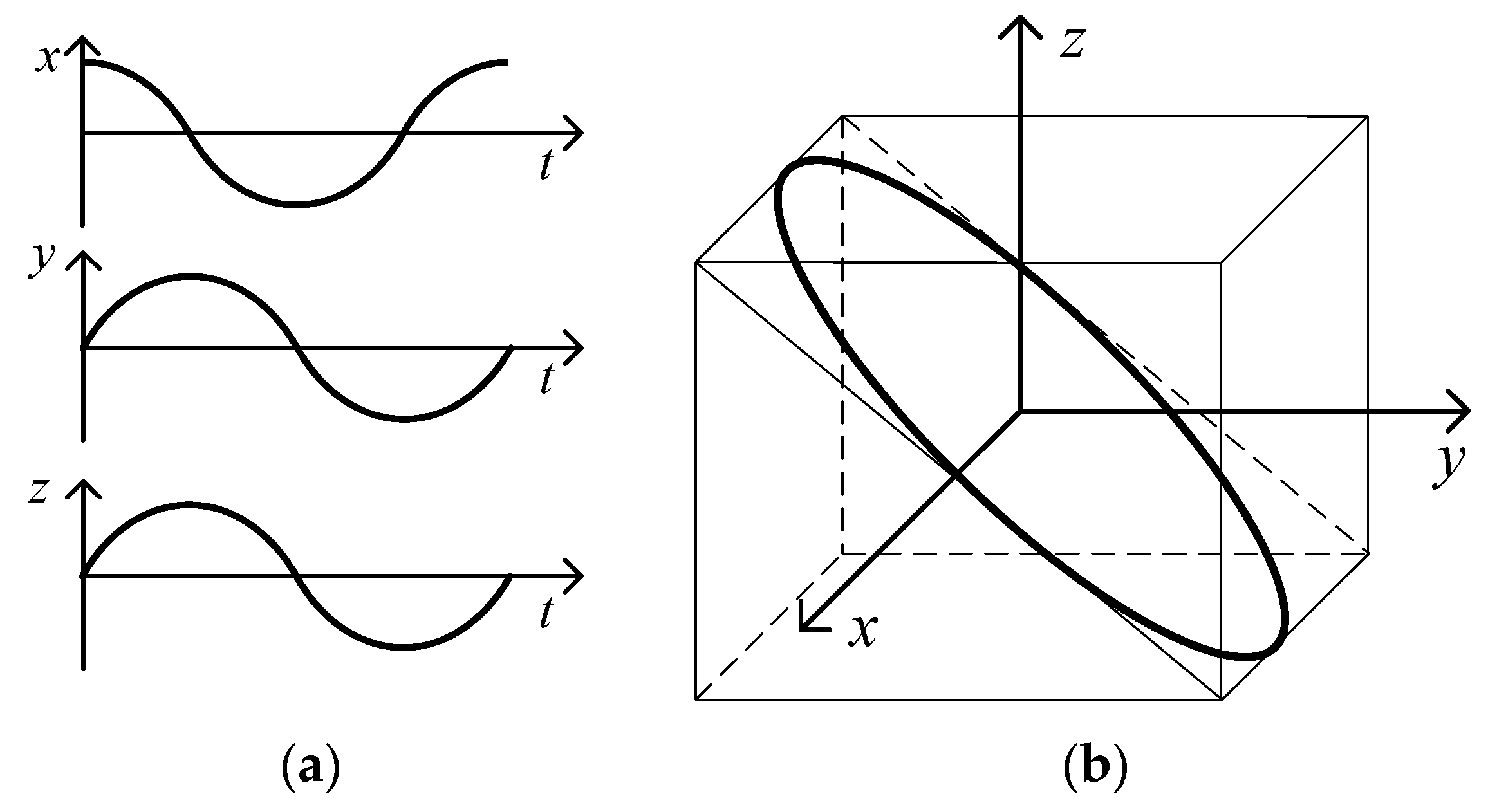
2.2. Spatial Orbits
3. Testing Using Spatial Orbits
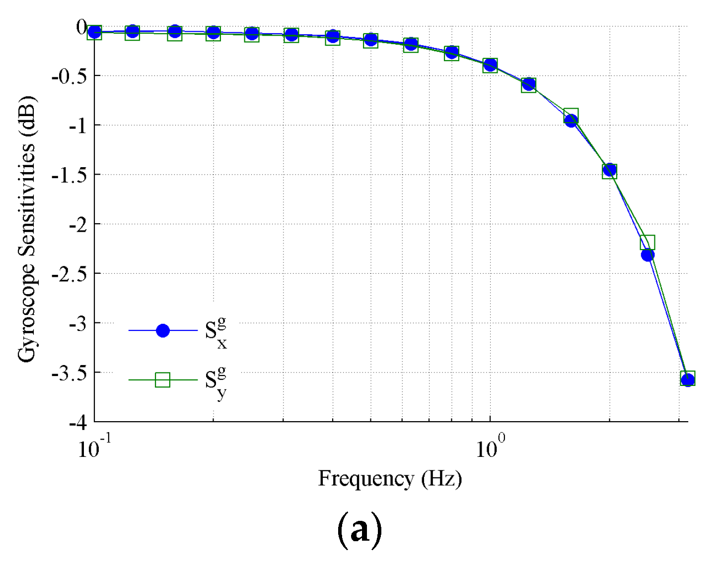
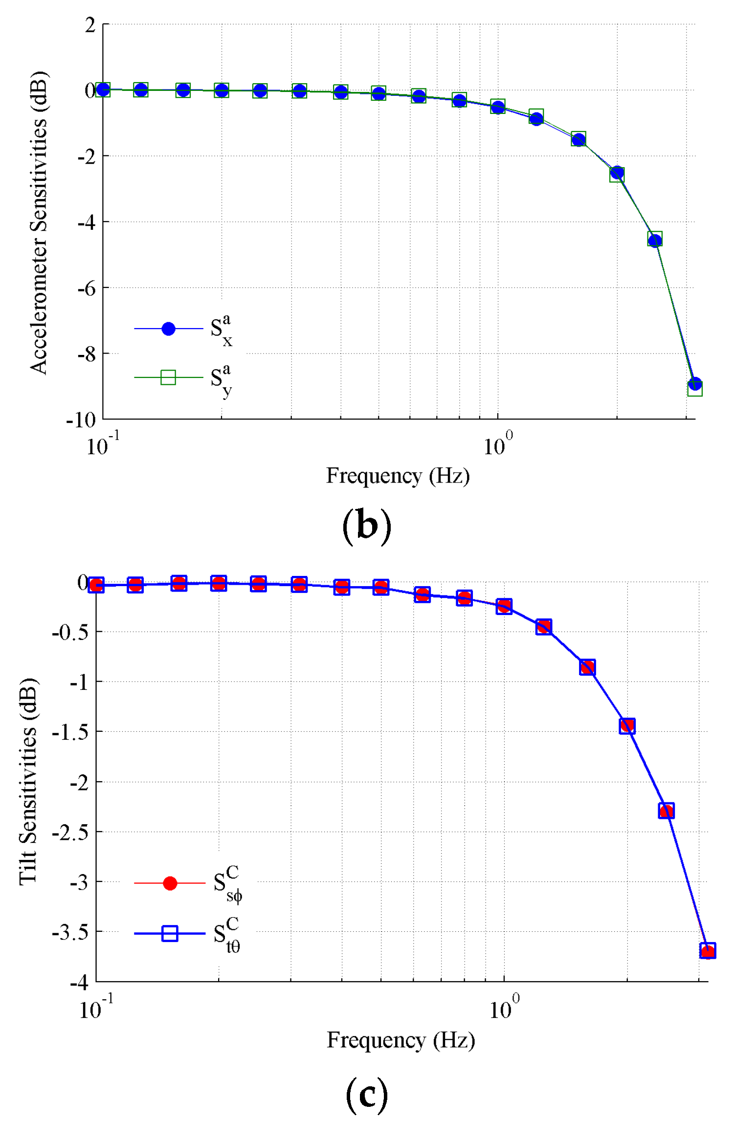
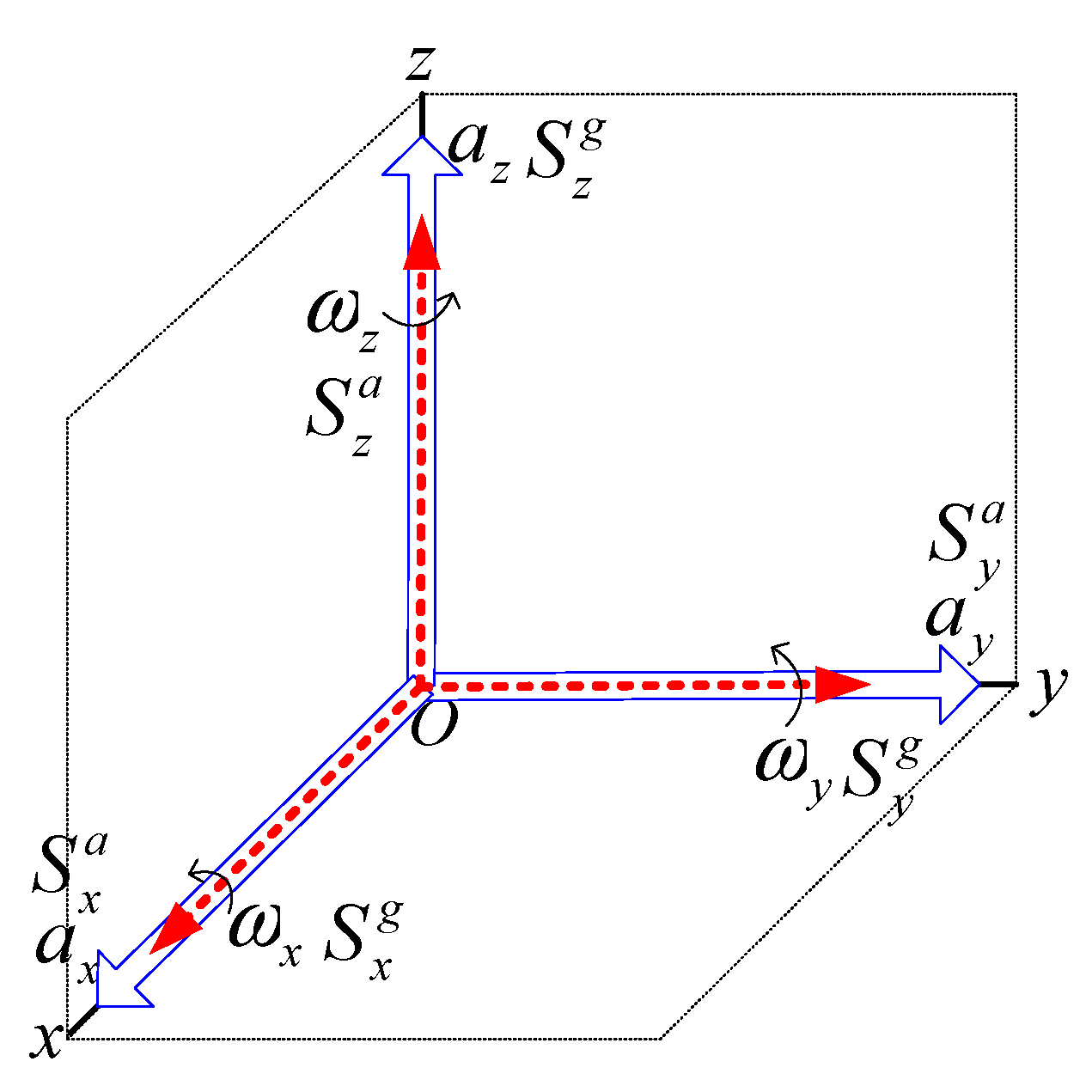
3.1. Gyroscope and Accelerometer
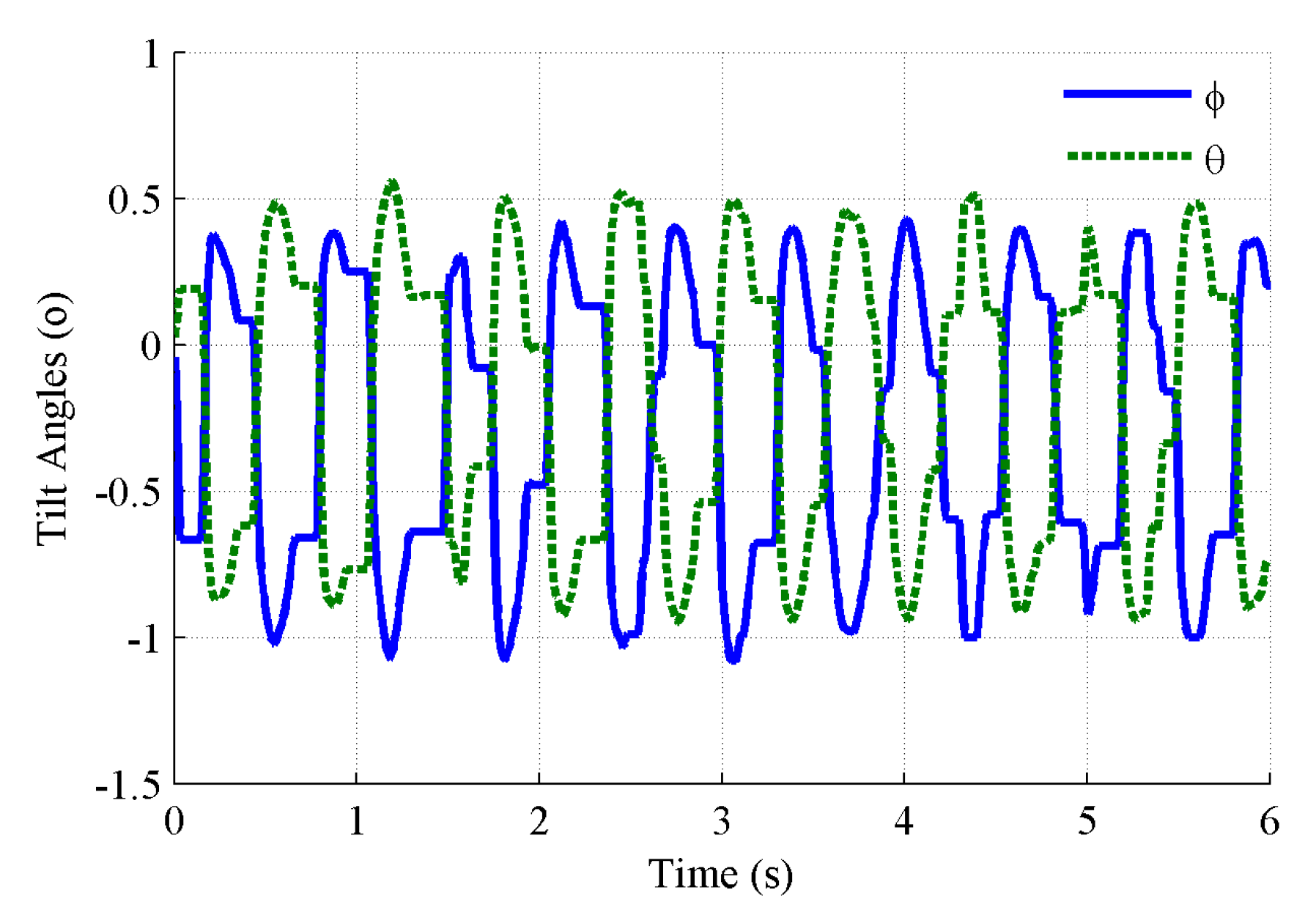
3.2. Tilt Sensing
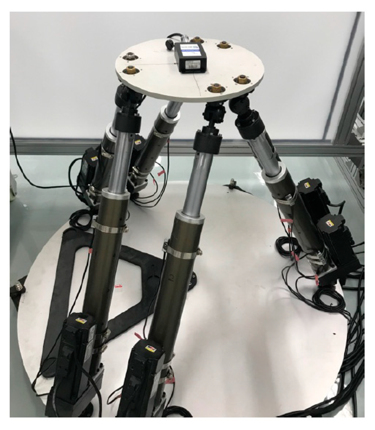
4. Experimental Investigation
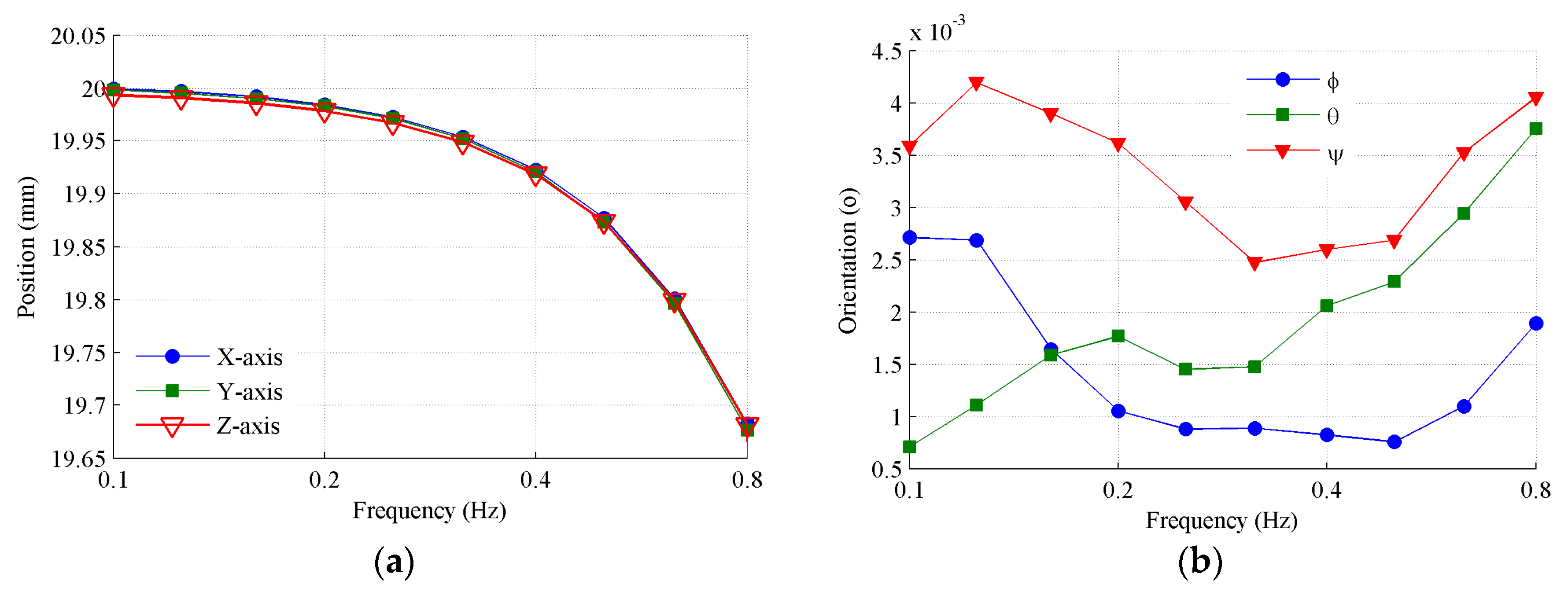
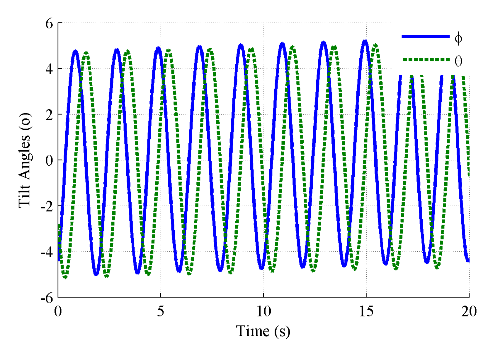
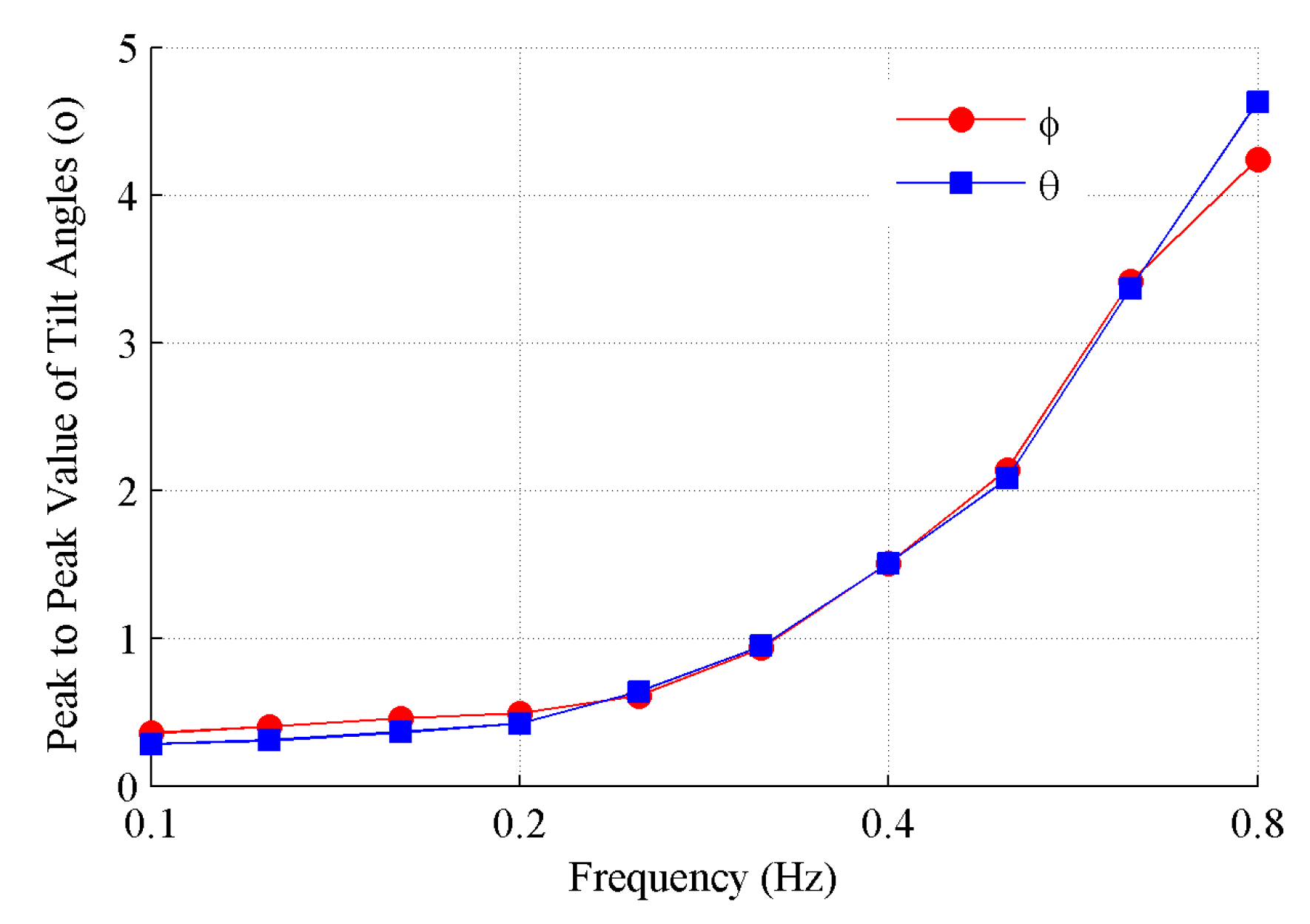
4.1. Tracking Performance
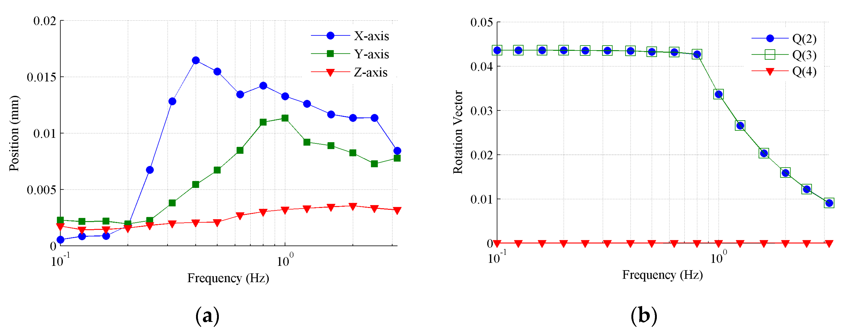
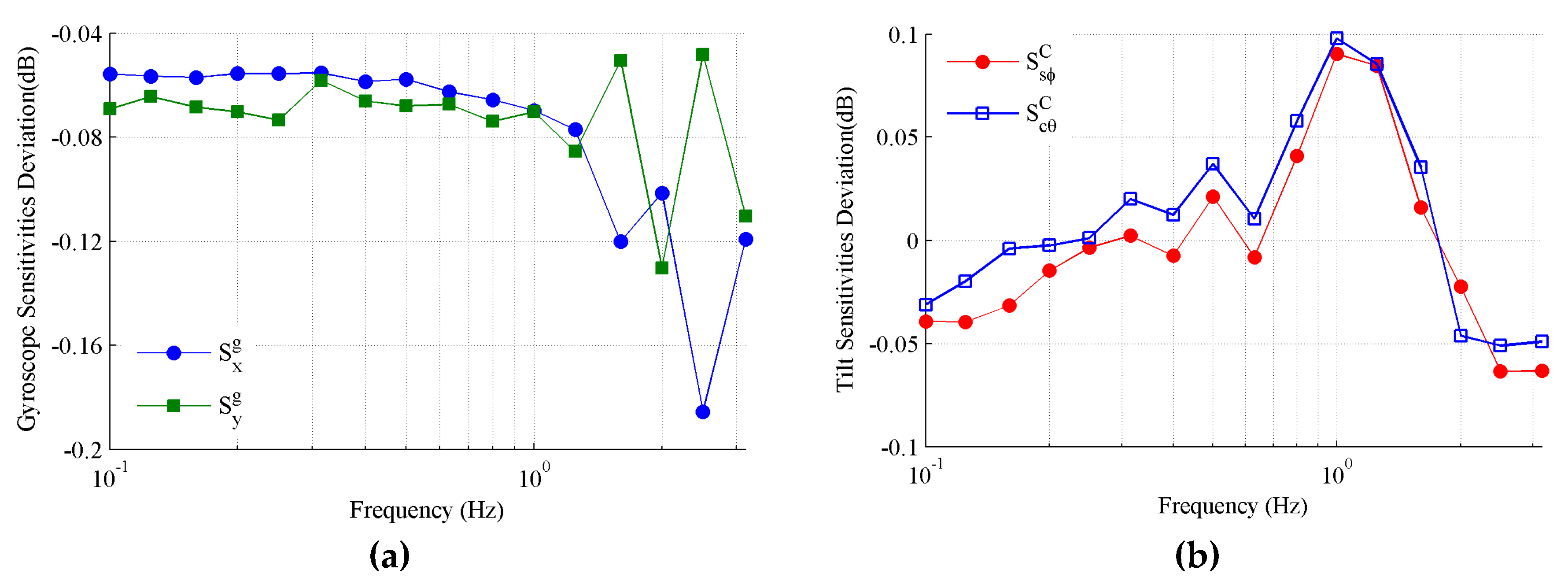
4.2. Cross Coupling
4.3. Comparison with the Rotator
5. Conclusions
Author Contributions
Funding
Conflicts of Interest
References
- Shaeffer, D.K. MEMS inertial sensors: A tutorial overview. IEEE Commun. Mag. 2013, 51, 100–109. [Google Scholar] [CrossRef]
- Bedon, C.; Bergamo, E.; Izzi, M.; Noè, S. Prototyping and validation of MEMS accelerometers for structural health monitoring-the case study of the Pietratagliata cable-stayed bridge. J. Sens. Actuator Netw. 2018, 7, 30. [Google Scholar] [CrossRef]
- Ha, D.; Park, H.; Choi, S.; Kim, Y. A wireless MEMS-based inclinometer sensor node for structural health monitoring. Sensors 2013, 13, 16090–16104. [Google Scholar] [CrossRef] [PubMed]
- Ha, D.W.; Kim, J.M.; Kim, Y.; Park, H.S. Development and application of a wireless MEMS-based borehole inclinometer for automated measurement of ground movement. Automat. Constr. 2018, 87, 49–59. [Google Scholar] [CrossRef]
- Member, S.N.; Touya, Y.; Nonmembers, S.T. Automatic on-line measurement of ship’s attitude by use of servo-type inclinometers. Electr. Commun. Jpn. 2010, 78, 91–102. [Google Scholar] [CrossRef]
- Akella, M.R.; Halbert, J.T.; Kotamraju, G.R. Rigid body attitude control with inclinometer and low-cost gyro measurements. Syst. Control Lett. 2003, 49, 151–159. [Google Scholar] [CrossRef]
- Gui, P.; Tang, L.; Mukhopadhyay, S. MEMS based IMU for tilting measurement: Comparison of complementary and kalman filter based data fusion. In Proceedings of the 2015 IEEE 10th conference on Industrial Electronics and Applications (ICIEA), Auckland, New Zealand, 15–17 June 2015. [Google Scholar]
- Ligorio, G.; Sabatini, A.M. A Novel Kalman filter for human motion tracking with an inertial-based dynamic inclinometer. IEEE Trans. Biomed. Eng. 2015, 62, 2033–2043. [Google Scholar] [CrossRef] [PubMed]
- Syed, Z.F.; Aggarwal, P.; Goodall, C.; Niu, X.; El-Sheimy, N. A new multi-position calibration method for MEMS inertial navigation systems. Meas. Sci. Technol. 2007, 18, 1897–1907. [Google Scholar] [CrossRef]
- Aggarwal, P.; Syed, Z.; Niu, X.; El-Sheimy, N. A standard testing and calibration procedure for low cost MEMS inertial sensors and units. J. Navig. 2008, 61, 323–336. [Google Scholar] [CrossRef]
- Ren, Y.; Wang, Y.; Wang, M.; Wu, S.; Wei, B. A measuring system for well logging attitude and a method of sensor calibration. Sensors 2014, 14, 9256–9270. [Google Scholar] [CrossRef] [PubMed]
- Cheuk, C.M.; Lau, T.K.; Lin, K.W.; Liu, Y. Automatic calibration for inertial measurement unit. In Proceedings of the 2012 12th International Conference on Control Automation Robotics & Vision (ICARCV), Guangzhou, China, 5–7 December 2012. [Google Scholar]
- Ren, C.; Liu, Q.; Fu, T. A novel self-calibration method for MIMU. IEEE Sens. J. 2015, 15, 5416–5422. [Google Scholar] [CrossRef]
- Fang, B.; Chou, W.; Ding, L. An optimal calibration method for a MEMS inertial measurement unit. Int. J. Adv. Robot Syst. 2014, 11, 1–14. [Google Scholar] [CrossRef]
- Gallardo-Alvarado, J. An overview of parallel manipulators. In Kinematic Analysis of Parallel Manipulators by Algebraic Screw Theory; Springer International Publishing: Switzerland, 2016. [Google Scholar]
- Liu, K.; Fitzgerald, J.M.; Lewis, F.L. Kinematic analysis of a Stewart platform manipulator. IEEE Trans. Ind. Electron. 1993, 40, 282–293. [Google Scholar] [CrossRef]
- Furqan, M.; Suhaib, M.; Ahmad, N. Studies on Stewart platform manipulator: A review. J. Mech. Sci. Technol. 2017, 31, 4459–4470. [Google Scholar] [CrossRef]
- Cardona, M. Kinematics and Jacobian analysis of a 6UPS Stewart-Gough platform. In Proceedings of the 2016 IEEE 36th Central American and Panama Convention (CONCAPAN XXXVI), San Jose, Costa Rica, 9–11 November 2016. [Google Scholar]
- Zhang, Y.; Yu, Y. Optimal design of 6DOF parallel robot based on output frequency response function. In Proceedings of the 2009 International Conference on Measuring Technology and Mechatronics Automation, Zhangjiajie, China, 11–12 April 2009. [Google Scholar]
- Jiang, H.Z.; He, J.F.; Tong, Z.Z. Characteristics analysis of joint space inverse mass matrix for the optimal design of a 6-DOF parallel manipulator. Mech. Mach. Theory 2010, 45, 722–739. [Google Scholar] [CrossRef]
- Wu, J.F.; Zhang, R.; Wang, R.H.; Yao, Y.X. A system optimization approach for the calibration of parallel kinematics machine tools by a laser tracker. Int. J. Mach. Tools Manuf. 2014, 86, 1–11. [Google Scholar] [CrossRef]
- Ji, P.; Wu, H. A closed-form forward kinematics solution for the 6-6/sup p/Stewart platform. IEEE T. Robotic. Autom. 2002, 17, 522–526. [Google Scholar]
- Pedley, M. Tilt sensing using a three-axis accelerometer. Freescale Semicond. Appl. Notes 2013, 3, 1–21. [Google Scholar]
- Liu, Z.; Cai, C.; Yu, M.; Yang, M. Applying spatial orbit motion to accelerometer sensitivity measurement. IEEE Sens. J. 2017, 17, 4483–4491. [Google Scholar] [CrossRef]


| Dynamic Accuracy | 0.1° | Tilt Range | Pitch ± 90°, Roll ± 180° |
|---|---|---|---|
| Static accuracy | 0.01° | Start delay | <50 ms |
| Resolution | 0.01° | Maximum output frequency | 100 Hz |
© 2019 by the authors. Licensee MDPI, Basel, Switzerland. This article is an open access article distributed under the terms and conditions of the Creative Commons Attribution (CC BY) license (http://creativecommons.org/licenses/by/4.0/).
Share and Cite
Liu, Z.; Cai, C.; Yang, M.; Zhang, Y. Testing of a MEMS Dynamic Inclinometer Using the Stewart Platform. Sensors 2019, 19, 4233. https://doi.org/10.3390/s19194233
Liu Z, Cai C, Yang M, Zhang Y. Testing of a MEMS Dynamic Inclinometer Using the Stewart Platform. Sensors. 2019; 19(19):4233. https://doi.org/10.3390/s19194233
Chicago/Turabian StyleLiu, Zhihua, Chenguang Cai, Ming Yang, and Ying Zhang. 2019. "Testing of a MEMS Dynamic Inclinometer Using the Stewart Platform" Sensors 19, no. 19: 4233. https://doi.org/10.3390/s19194233
APA StyleLiu, Z., Cai, C., Yang, M., & Zhang, Y. (2019). Testing of a MEMS Dynamic Inclinometer Using the Stewart Platform. Sensors, 19(19), 4233. https://doi.org/10.3390/s19194233