1. Introduction
Landslide is part of the most disastrous geological hazards, occurring due to rainfall, earthquake load, steep slopes and human activities, and causing thousands of casualties, significant damage, and economic loss [
1,
2]. In the Shuping landslide, in May 2004, approximately 163 families (around 580 people) were relocated. Recently, at least 10 people were killed and 22 others are missing after a rain-triggered landslide buried mountain-side factories in northwestern Shaanxi province. Internal horizontal displacements of slope can provide deformations at different depths and determine the magnitude, rate, direction, depth, and type of landslide movement. Thus, it is important for researchers to understand the deformation mechanisms of landslides, analyze the slope stability, provide an early warning to the public, and protect lives and property [
3,
4].
In the past several decades, various geotechnical instruments and measurement methods have been developed and adopted for measuring the internal displacements of slopes [
5]. Traditional measurement methods mainly consist of an inclinometer [
6], linear variable differential transformers (LVDTs) [
7], an inductive displacement sensor [
8], and multi-point extensometers [
9]. A corresponding evaluation with respect to the slope stability can be implemented by analyzing displacement distributions measured using the above sensors. In spite of this, it shows several disadvantages, including poor moisture-proofness, signal loss for long distance transmission, poor durability, and the fact that active devices require power supply, etc. As a particular class of sensors, fiber Bragg grating (FBG) sensors have received much attention due to their prominent advantages, such as being immune to electromagnetic noise, being waterproof, easy multiplexing, a negligible weight and size, high precision, etc. [
10,
11]. A variety of FBG-based sensors [
12], such as the FBG-segmented deflectometer, FBG strain gauge and FBG tilt sensor, have been designed for the real-time measurement of different mechanical parameters, including internal displacements, strains and inclination angles, etc., so as to conduct a safety evaluation of slopes. Nevertheless, most of the aforementioned FBG sensors can only monitor the parameters that are related to slope stability with the point-mode. They are inapplicable for measuring the whole internal displacement profiles of the slope and for locating the sliding surfaces.
To tackle the above-mentioned limitations, some FBG-embedded flexible sensors that were fabricated by integrating the FBG arrays into flexible substrates have been widely adopted to capture the displacement profiles in the field of robotics, medical engineering, aerospace, infrastructure and geotechnical engineering [
13,
14]. These FBG flexible sensors could be pre-installed in the structure to be measured, utilizing shape reconstruction algorithms to reconstruct the displacement profile distributions. The deformed shape reconstructions of flexible sensors are crucial to accurately measure the structural displacement profiles. Bhamber et al. [
15] and Xu et al. [
16] adopted bidirectional curvatures and a curve fitting algorithm to reconstruct the shapes of the robotic arm and soft surgical actuator. Yi et al. [
17] developed a shape reconstruction method based on spatial movable coordinates, and realized the reconstruction of the flexible morphing wing shape. Derkevorkian et al. [
18] utilized strain information of the swept plate structure and a series of displacement transfer functions to estimate the corresponding displacement fields. Kim et al. [
19] investigated a deflection estimation technique for measuring the shape of rotating blades, which was based on distributed strain information and a displacement-strain transformation (DST) matrix obtained from the modal approach. Bang et al. [
20] created a finite element model based DST matrix for the estimation of wind turbine structures. In the field of geotechnical engineering, researchers have studied shape sensing methods for measuring displacement profiles in critical areas based on the FBG-embedded flexible sensors. Wang et al. [
21] fabricated an intelligent geogrid embedded with FBG sensors and employed a curvature-based reconstruction method to estimate the displacements related to geotechnical engineering. Kim et al. [
22] utilized a regression analysis method to measure the deflection curves, and subsequently adopted the method for the evaluation of bridge displacements. Li et al. [
23] and Zhu et al. [
24] established strain-deflection relationships for FBG flexible rods, which were then used in physical model tests to measure displacement profiles in an underground cavern group and dam. As far as monitoring the internal displacements of slopes was concerned, Pei et al. [
25] developed a new type of FBG-based in-place inclinometer for slope monitoring according to the classical indeterminate beam theory. Guo et al. [
26] estimated the displacement profiles of the slope using the curvatures and deflection angles detected by the FBG flexible sensor. The above scholars, with comprehensive insights in the field of FBG shapes sensing, have propelled research forward, and the technology has advanced to achieve an excellent performance in their respective application fields.
In practical applications, encounters with accumulative measurement errors are unavoidable during the displacement profile reconstruction employing that abovementioned methods. This is due to the temperature impacting the FBG points, the differences in the strain transfer rates, and the layout intervals of FBG sensing points, etc. These inefficiencies can be overcome by using the suitable correction method for correcting the reconstructed displacements, as well as by improving the measurement accuracy. So far, some works have already made progress in the error analyses and corrections of shape sensing. Sun et al. [
27] experimentally calibrated the relationships between bending curvatures and wavelength-shifts at each sensing point in order to reduce strain transferring errors, and adopted a linear interpolation of the curvatures to improve the reconstruction accuracy of polyimide film deformations. Abayazid et al. [
28,
29,
30] optimized the placement of sensing points and used the k-nearest neighbor interpolation model to reconstruct the curvature functions, and the proposed methods were conducted to improve the reconstruction precision of structural deformations. Zhang et al. [
31] developed the least mean square algorithm based parameter identification method and the construction of the dynamic error analysis model, which has been employed to shape reconstructions and error analyses of space plate structures. Wang et al. [
32] investigated an in-situ calibrated deformation reconstruction method, and improved the estimation accuracy of deformation fields effectively.
Although the correction methods being leveraged in the aforementioned studies have mitigated the accumulative errors and improved the accuracy of measured displacement profiles, they corrected the measured displacements without considering the diversity of deformation forms. It was found in the author’s previous research [
33] that the correction method depended highly on the deformation forms. The displacements with a variety of deformed configurations cannot be universally corrected using one established and unique correction coefficient. The best way is to determine the correction weights for different bending shapes and then correct the reconstructed displacements accordingly. For the task of the internal horizontal displacements monitoring in the slopes, the displacements to be measured sometimes cover a long-distance range in the vertical direction. Furthermore, the displacements at different depths of the slopes are extremely complex during the evolution process of landslides. As a result, the internal horizontal displacements may have a variety of deformed shapes along dissimilar positions of the slope. Therefore, the displacement profile sensing method and correction method for monitoring the internal displacements should be able to automatically identify the deformation segments with different bending shapes, and then correct the different deformation segments according to the corresponding correction coefficients. Nevertheless, the methods of automatic identification of deformation segments and segmental correction have seldom been studied. Therefore, the ultimate goal of the current research is to develop a displacement profile reconstruction and correction method dedicated to the FBG flexible sensor for the internal displacement profiles monitoring of the slope.
In this paper, we proposed a segmental correction method based on strain increment clustering with the characteristics of self-correction displacement profile reconstruction, which had the ability to identify and correct deformation segments automatically for different bending shapes of the flexible sensor. Specifically, we calculated the strain increments at sensing points and extracted them as eigenvalues to be clustered. Then the clustering algorithm was employed to cluster the strain increments so that the deformation segments with different bending shapes of the flexible sensor could be identified automatically. The correction coefficients of the deformation segments were determined by calibrating the typical bending shapes of the sensor in the measurement of the slope displacement profiles, and the optimization algorithm was adopted to determine their optimal values. The remainder of the paper was organized as follows: in
Section 2, the correction method of shape sensing was explained in detail. Then, in
Section 3, a finite element simulation was conducted to verify the displacements sensing effects. Next, we conducted an FBG flexible sensor fabrication, experiment and analysis in
Section 4. Finally,
Section 5 presents the concluding remarks.
3. Simulation Verification
In this paper, a finite element method was applied to simulate the bending shapes of the FBG flexible sensor, and the effects of displacement sensing that had been adopted in unified correction and segmental correction were compared. To remain consistent with the flexible sensor of plate-like structure used in the experiment, a slender plate model with a length of 1900 mm, a width of 10 mm and a thickness of 2 mm was established, as shown in
Figure 5a
1,b
1,c
1. The initial end surface (the bottom of the slender plate model) central coordinates were
O (0, 0, 0), and the slender plate model was divided into 19 segments along the
y-axis (length direction). Each segment was to be regarded as a beam element of the FBG flexible sensor. The slender plate material was epoxy resin, and its mechanical property parameters were listed in
Table 1. In this study’s simulation, the slender plate model had a total of 18,785 meshes with minimum unit masses of 0.2418. After that, with consideration given to the geometrical nonlinearity of the material applied in the simulation, an elastic model was selected.
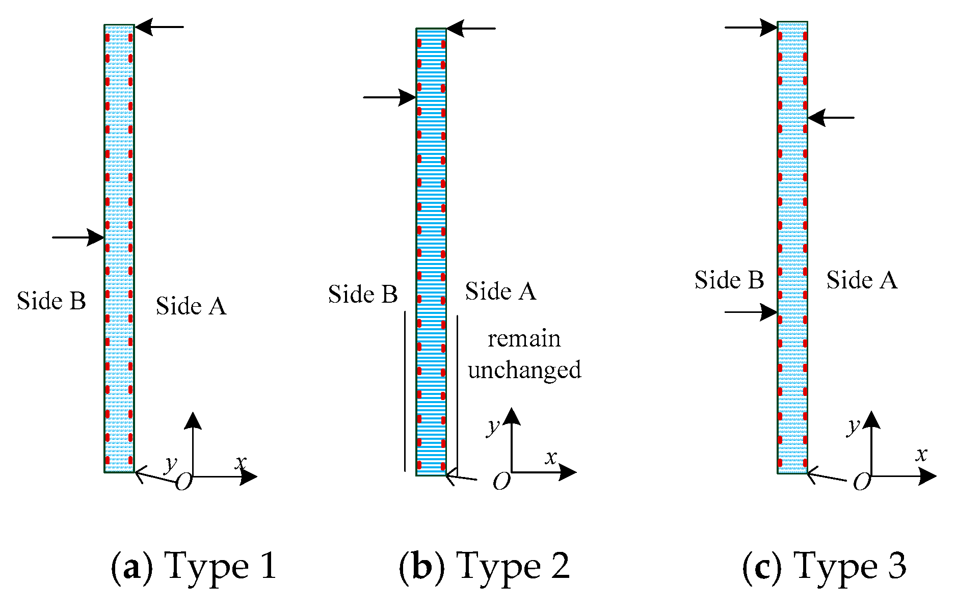
A displacement constraint was fixed on the bottom of the slender plate, and three different types of displacements were exerted to simulate the possible bending shapes of the flexible sensor in monitoring the internal displacements of the slope. For Type 1 (
Figure 5a
1), the displacements of the slender plate model (from the bottom to the 7-th measuring point) were constrained to zero. 100 mm and 0 mm displacements were exerted along the
x direction at (−1, 1300, 0) and (−1, 1900, 0), respectively. For Type 2 (
Figure 5b
1), the displacements (from the 8-th measuring point to the 11-th measuring point) were constrained to zero. The displacements were imposed on the slender plate at (−1, 400, 0), (−1, 1500, 0) and (−1, 1900, 0) along the
x direction, respectively, and the displacement values were 100 mm, 80 mm and 0 mm, respectively. For Type 3 (
Figure 5c
1), −100 mm and 0 mm displacements were exerted along the
x-axis at (−1, 400, 0) and (−1, 800, 0), respectively.
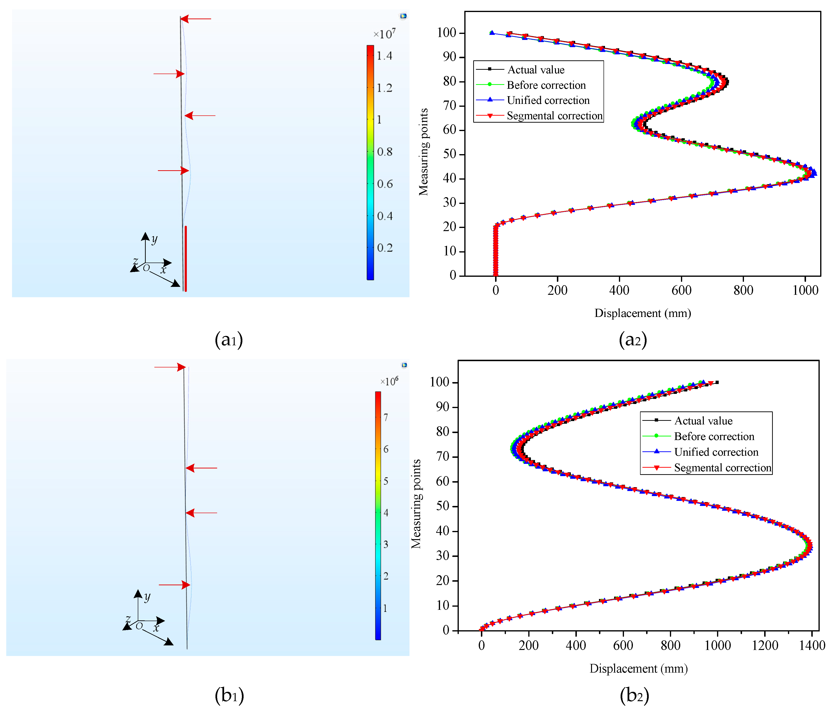
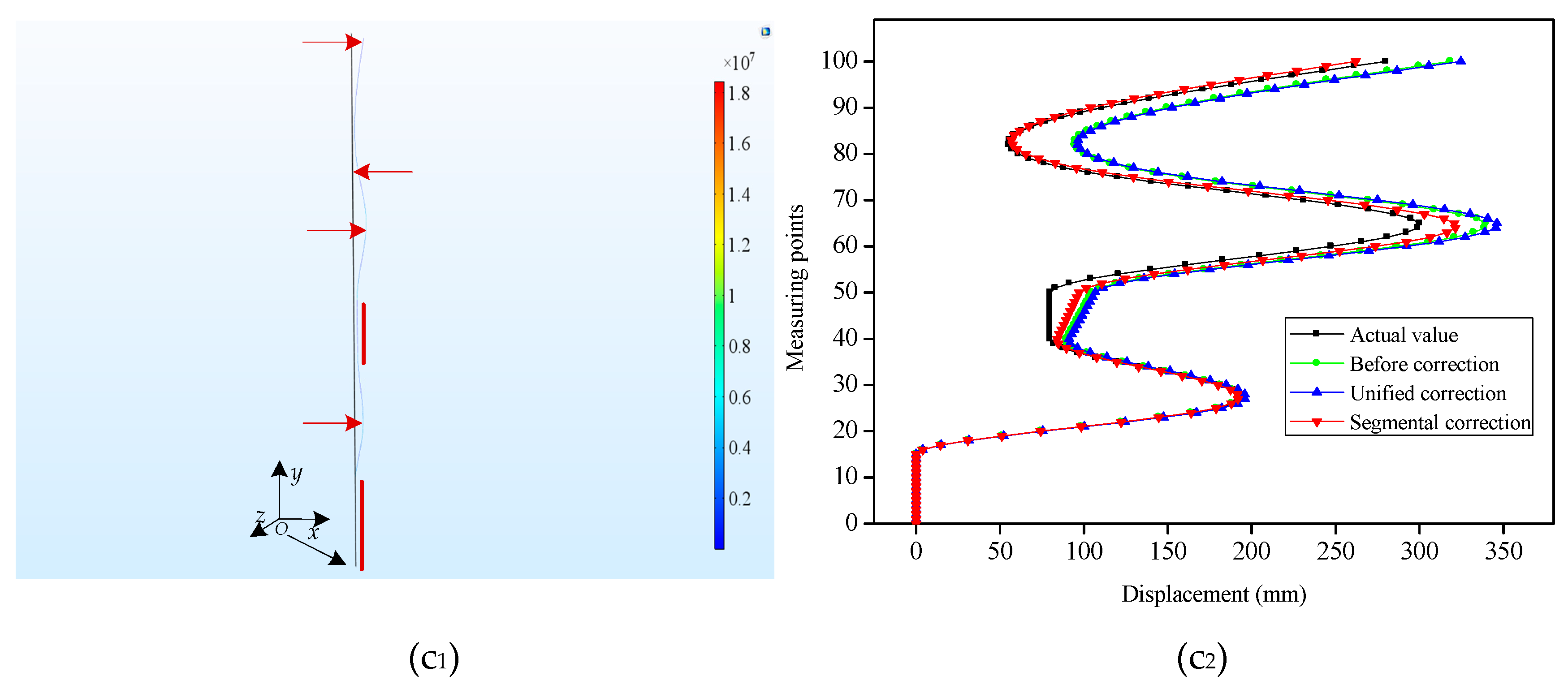
Considering the practical engineering application, for the task of internal horizontal displacements monitoring in the slopes, the displacements to be measured sometimes cover a long-distance range in the vertical direction. To simulate this circumstance, a slender plate model of epoxy resin material with a length of 10,000 mm, width of 10 mm and thickness of 2 mm was also simulated. Its bending shapes were represented in
Figure 6a
1,b
1,c
1. For Type 4 (
Figure 6a
1), 1000 mm, 500 mm, 750 mm and 50 mm displacements were applied along the
x-axis at (−1, 4000, 0), (−1, 6000, 0), (−1, 8000, 0) and (−1, 10,000, 0) on the slender plate model, respectively. Meanwhile, the displacements from the bottom to the 20-th measuring point were constrained and remained unchanged. For Type 5 (
Figure 6b
1), we applied 1000 mm, 100 mm, 300 mm and 1000 mm displacements along the
x direction at (−1, 2000, 0), (−1, 5000, 0), (−1, 6500, 0) and (−1, 10,000, 0), respectively. For Type 6 (
Figure 6c
1), the displacements of two regions (from the bottom to the 15-th measuring point and from the 40-th measuring point to the 50-th measuring point) were constrained to zero and 80 mm, respectively. Meanwhile, the displacements were imposed to the slender plate model at (−1, 2500, 0), (−1, 6500, 0), (−1, 7500, 0) and (−1, 10,000, 0) along the
x direction, respectively, and the displacement values were 180 mm, 300 mm 120 mm and 280 mm, respectively.
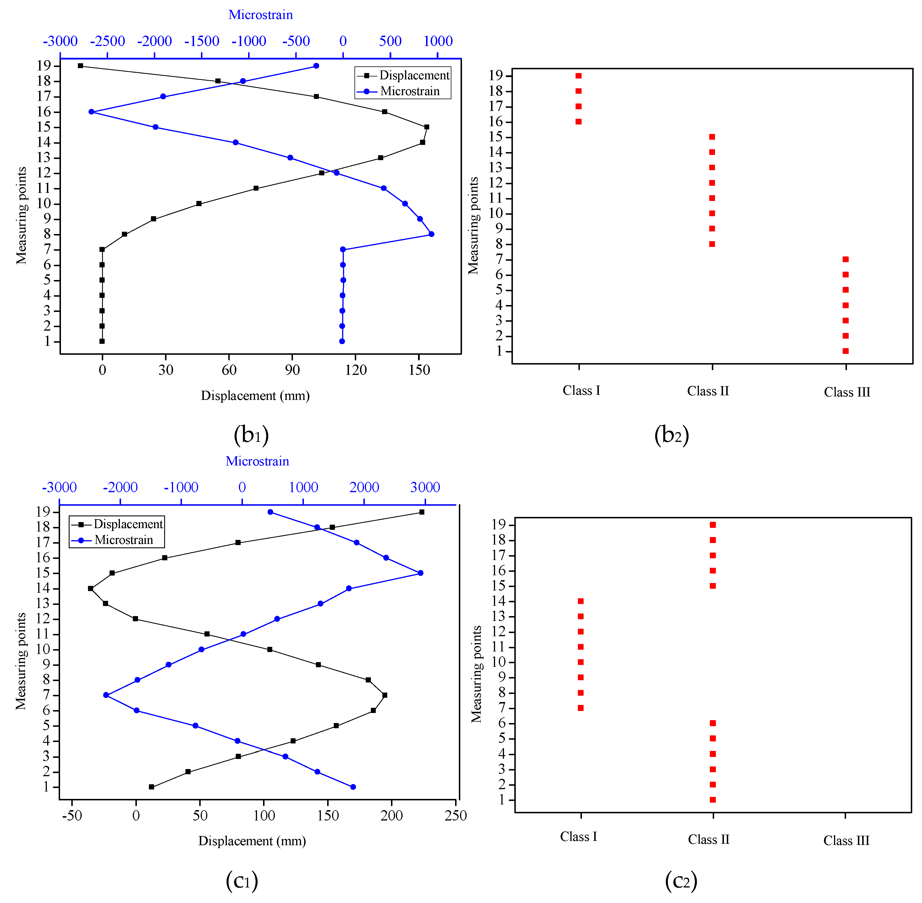
For the six typical bending shapes, the strain values in the coordinate points of Si (−1, 50 + 100 × i, 0) with i = 0, 1... m were extracted from the slender plate model. Meanwhile, the displacements in the coordinate points of Pj (−1, 100 × j, 0) with j = 1, 2, ..., n were extracted as the standard displacement values. For Types 1, 2 and 3, m and n were 18 and 19 respectively, while for Types 4, 5 and 6, m and n were 99 and 100, respectively. By using the standard displacement values of the measuring points as the benchmark, the optimization goal was to minimize the MAEs between the reconstructed displacements and actual displacements at each measuring point. Different deformation segments under each typical bending shape of the slender plate were categorized into different classes by using the K-means clustering algorithm. Then, a PSO optimization algorithm was adopted to calculate the correction coefficients for different classes and define the unified correction coefficient of the overall deformation as a comparison at the same time. The correction coefficients for Class I and Class II were determined to be k1 = 0.96 and k2 = 1.07, respectively, and the unified correction coefficient was k0 = 1.02. To be clear, the correction coefficients (k1, k2, and k0) were the average values under three bending shapes (Type 1, 2 and 3). These correction coefficients were also employed in Types 4, 5 and 6 to contrast the displacement sensing effects under different methods.
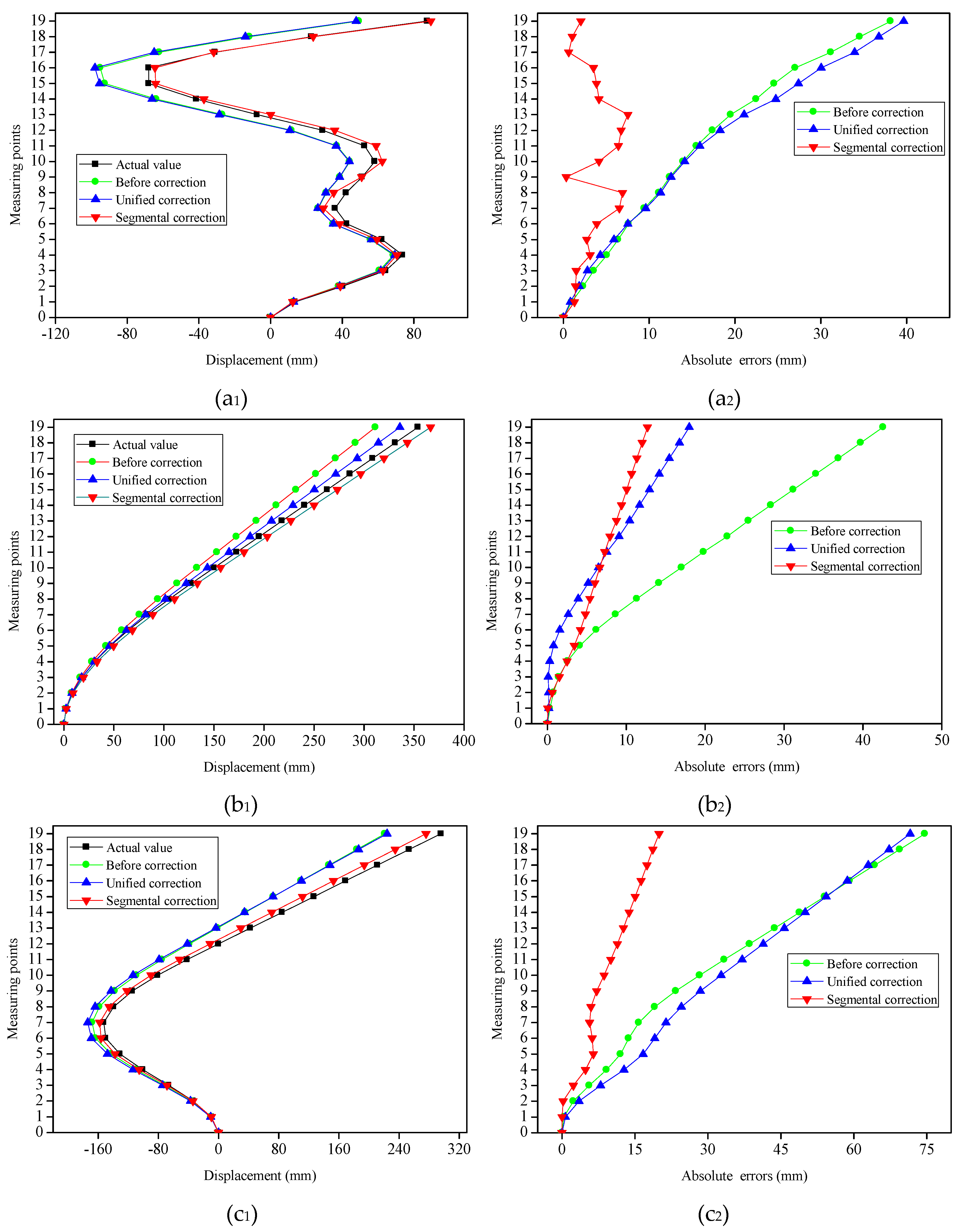
To obtain the displacements of the measuring points under different bending shapes, the strain values which had been extracted were employed for the reconstruction of the different bending shapes of the slender plate via the shape reconstruction algorithm.
Figure 5a
2,b
2,c
2 and
Figure 6a
2,b
2,c
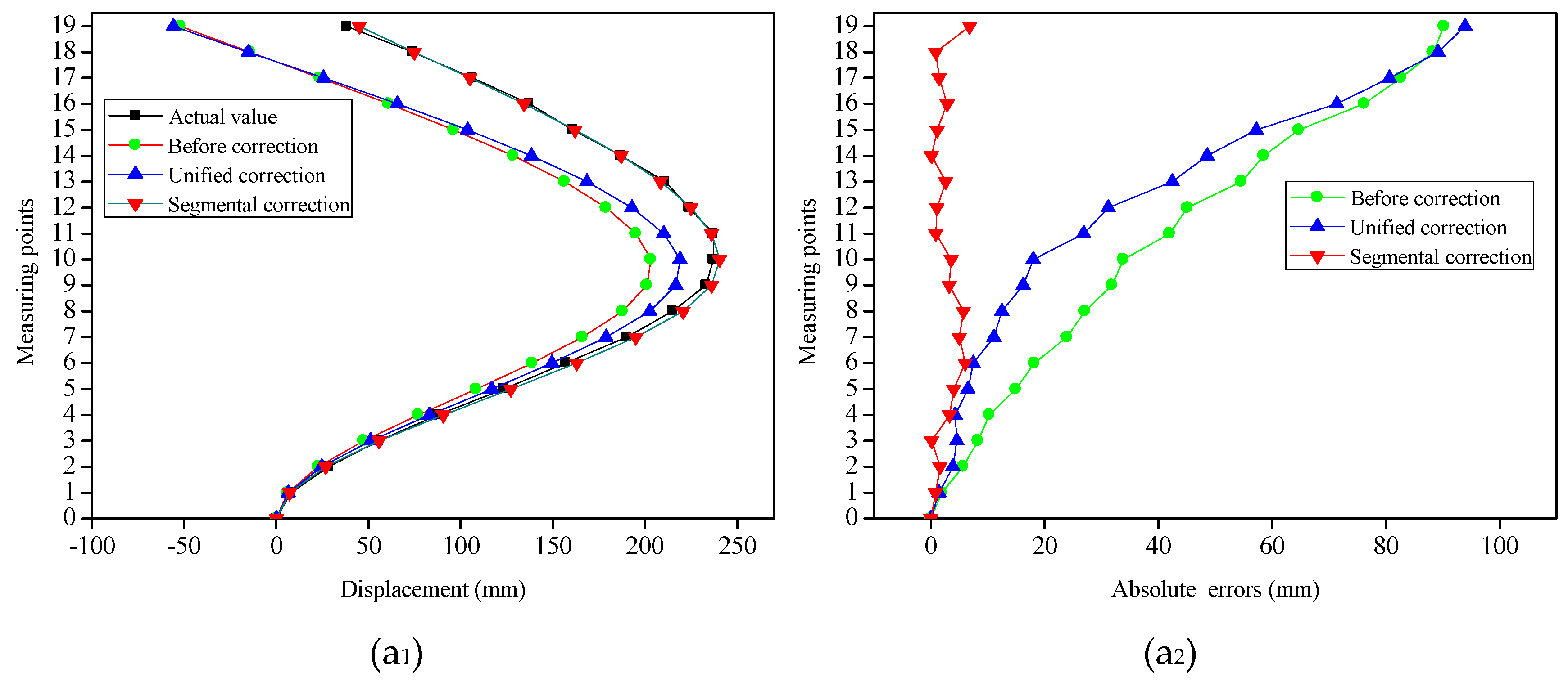
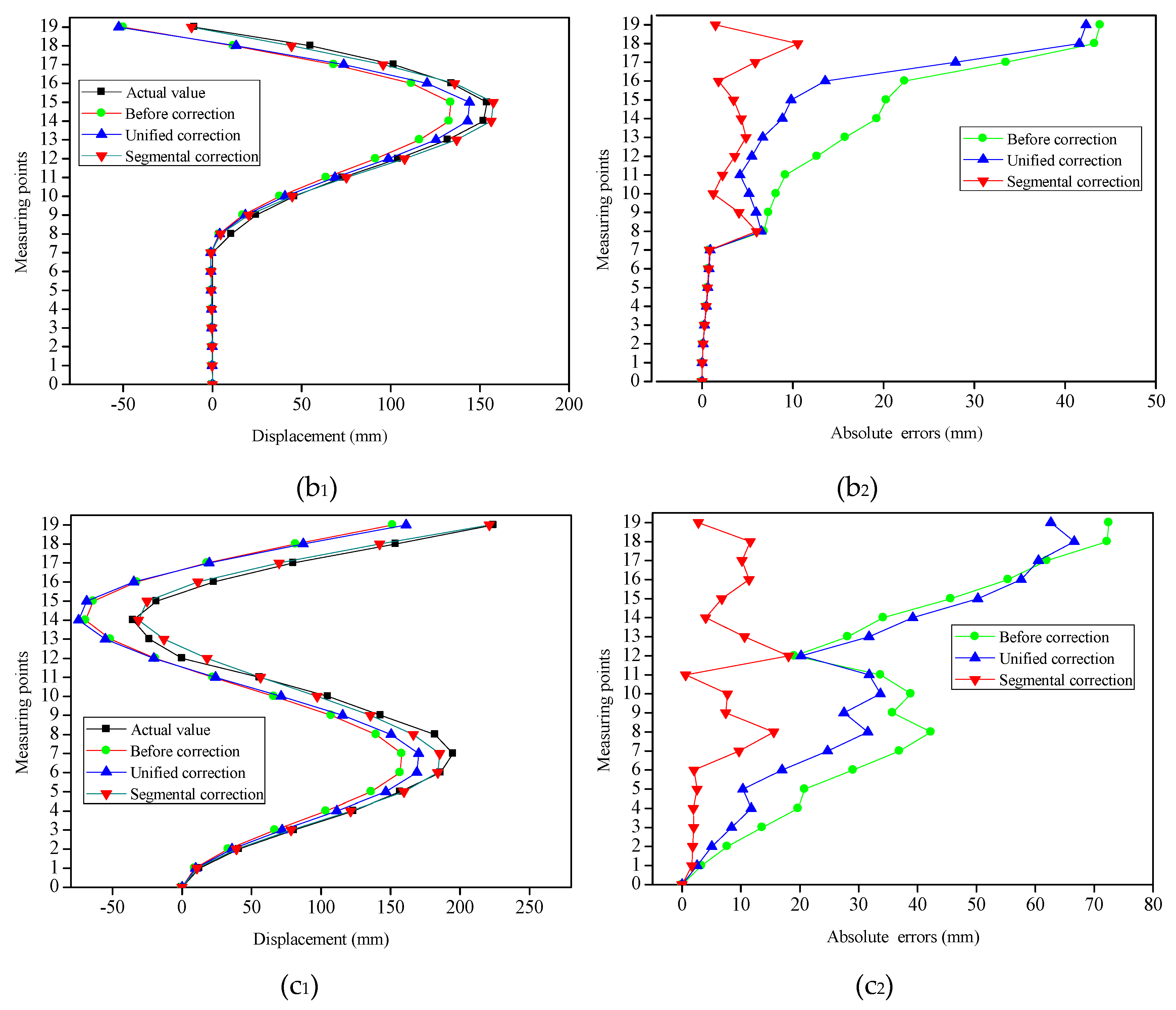
2 displayed the contrast between the displacements of the measuring points before and after the corrections, as well as the actual displacements under the different bending shapes. It can be seen that, having been influenced by multiple factors (such as the accumulated errors of the measuring points), there were certain errors between the initial reconstructed displacements and the actual displacements. It was observed for Types 2, 3, 4 and 5 that the absolute errors of the measuring points away from the fixed end (the bottom of the slender plate) had gradually increased (with maximum errors of 31.87 mm, 56.38 mm, 62.76 mm and 71.52 mm, respectively), and both were located at the last measuring point. However, for Types 1 and 6, the measuring points with the maximum absolute errors were located in the 10-th, and 16-th points, with absolute error values of 20.78 mm and 40.08 mm, respectively. This was determined to be due to the fact that the displacement errors of the measuring points displayed the phenomena of positive and negative error offsets. It was obvious that the initial reconstructed displacements of the measuring points had larger errors for each type.
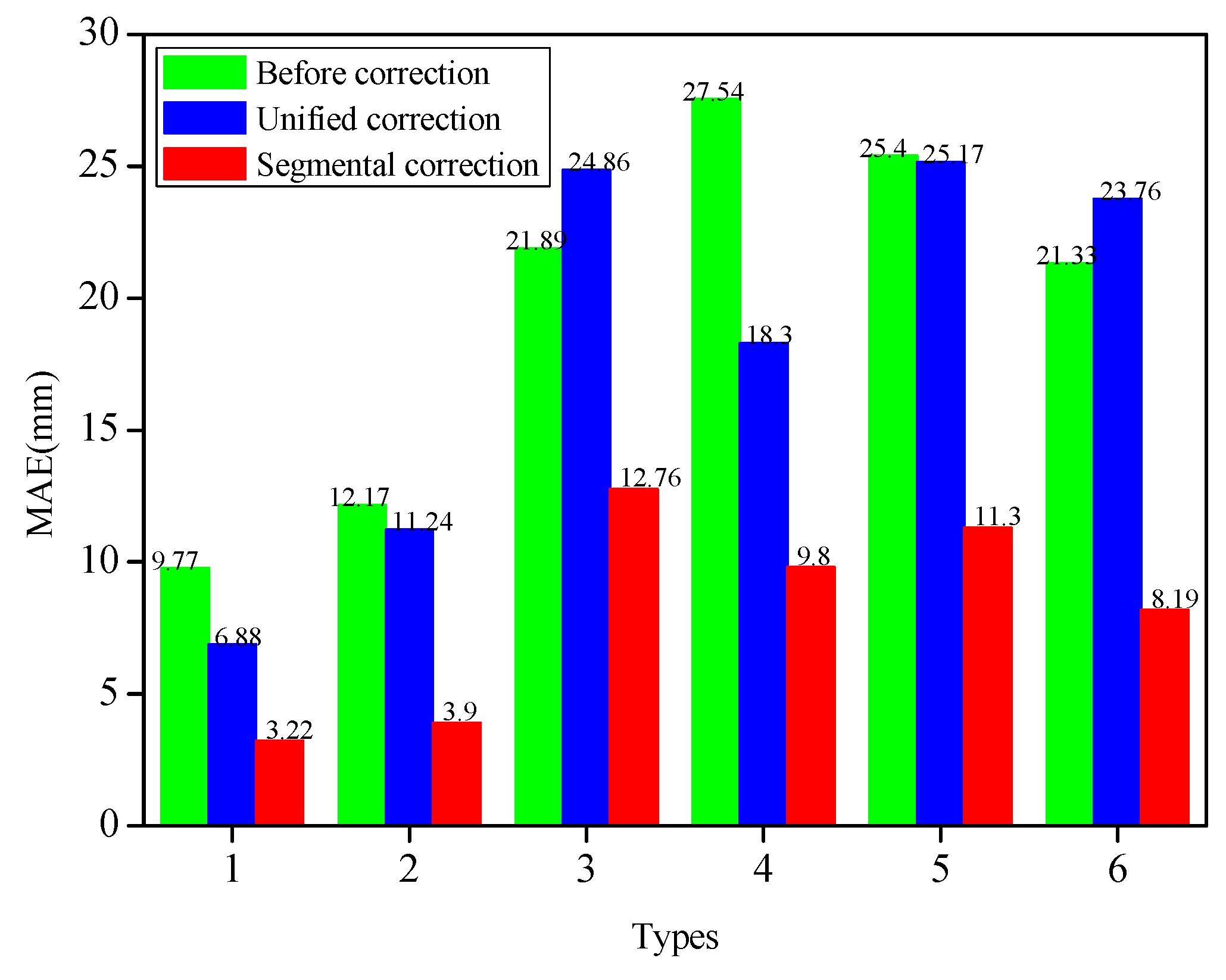
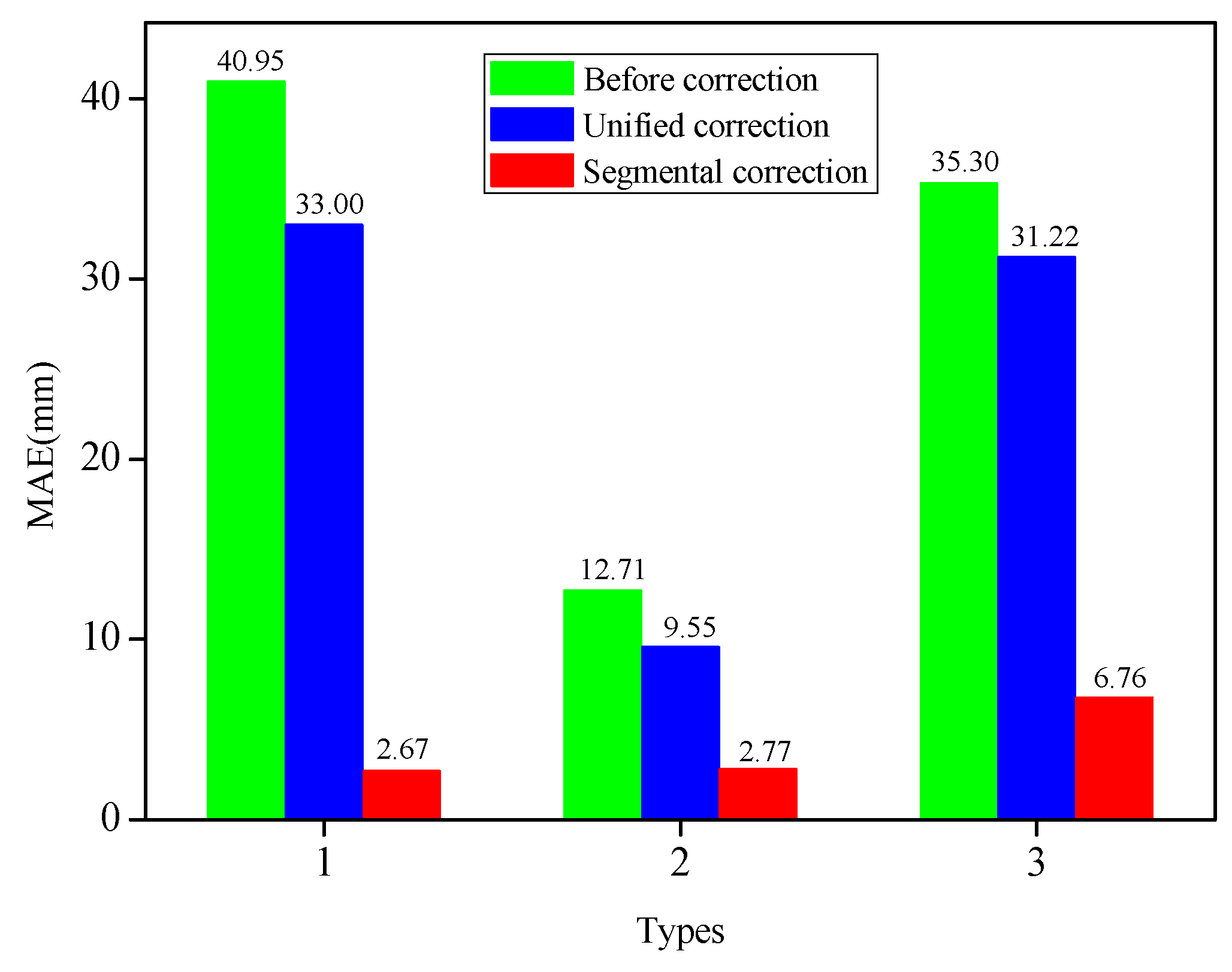
Figure 7 depicted the MAEs of the measuring points under three modes of initial reconstruction, unified correction and segmental correction. The extracted strain values for each bending shape were corrected by the unified coefficient, and the MAEs of the measuring point demonstrated larger differences. For instance, for Types 1, 2, 4 and 5, the MAEs of the corrected measuring points were decreased by 2.89 mm, 0.93 mm, 9.24 mm and 0.23 mm, respectively, compared with those before the correction. Nevertheless, for Types 3 and 6, the MAEs of the measuring points were augmented by unified corrections, which were 2.97 mm and 2.43 mm, respectively. Therefore, this fully testified to the fact that it was not competent to use the unified correction method to correct different bending shapes. However, the absolute errors of the six bending shapes had been determined to decline significantly after the strain values of different deformation segments for each bending shape were corrected by the segmental coefficients. The MAEs of Types 1, 2, 3, 4, 5 and 6 after the segmental corrections were 3.22 mm, 3.90 mm, 12.76 mm, 9.8 mm, 11.3 mm and 8.19 mm, respectively. The MAEs had dwindled by 6.55 mm (Type 1), 8.27 mm (Type 2), 9.13 mm (Type 3), 17.74 mm (Type 4), 14.1 mm (Type 5), and 13.14 mm (Type 6), respectively, following the segmental corrections. The segmental correction coefficients determined by Types 1, 2, and 3 were also applied to Types 4, 5, and 6 with good correction performances. The segmental coefficients correction showed its advantages in correcting the displacement errors of the measuring points with different bending shapes when compared with the unified coefficient correction. These findings indicated that the segmental correction method had the ability to improve the displacement accuracy of the measuring points with different bending shapes, which confirmed that it was necessary and feasible to use segmental correction for the various bending shapes.
5. Conclusions
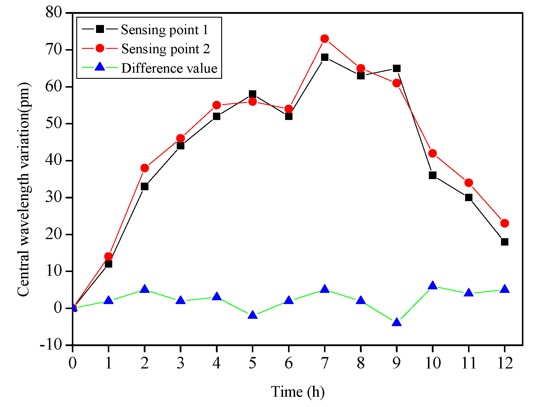
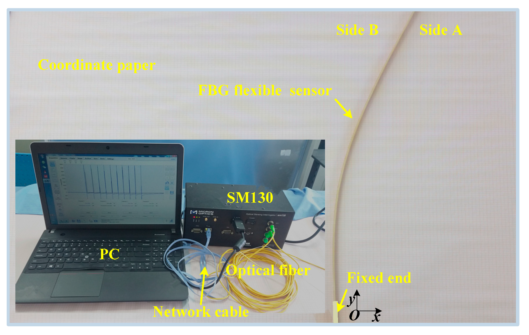
In this research, a self-correction displacement profiles sensing method based on strain increment clustering was proposed, which had ability to improve the accuracy of the FBG flexible sensor for measuring the horizontal displacement profiles inside the slope. Unlike the traditional correction method which calibrated the entire deformed shape and then applied the unified coefficient to correct the structures to be measured, our method was competent in automatically identifying different deformation segments using a K-means clustering algorithm based on strain increments at sensing points. After that, the correction coefficients of the deformation segments were determined by calibrating the typical bending shapes of the FBG flexible sensor in the measurement of the slope displacement profiles, and the PSO optimization algorithm was employed to achieve their optimal values. In addition, a finite element method was adopted to simulate six typical bending shapes of a slender plate model, and the necessity and feasibility of the proposed correction method were analyzed in detail. Furthermore, the operability and convenience of the experiment needed to be taken into consideration, and an FBG flexible sensor was fabricated by integrating the FBG sensing points with a flexible epoxy resin plate substrate. A temperature sensing experiment was performed to determine that the influences of temperature fluctuations could be eliminated by using differences of the central wavelength variations between two sensing points in each beam element. Finally, in order to validate the feasibility and effectiveness of the proposed method, the displacement calibration experiment was implemented. The clustering results of each type indicated that different deformation segments of the flexible sensor have been correctly categorized by the K-means clustering algorithm. Following the segmental corrections, the MAE percentages of six types were 1.87% (Type 1), 5.28% (Type 2), 6.98% (Type 3), 7.62% (Type 4), 4.16% (Type 5) and 8.31% (Type 6), respectively, which was an improvement of the accuracy by 26.83%, 18.94%, 29.49%, 26.35%, 7.39%, and 19.65%, respectively. The contrast of displacement sensing in four modes (actual value, initial reconstruction, unified correction and segmental correction) fully illustrated the feasibility and validity of the segmental correction method. Overall, these findings indicated that a self-correction displacement profiles sensing method based on strain increment clustering was empowered to effectively improve the displacement accuracy of measuring points with different bending shapes for the FBG flexible sensor. This method has broad application prospects in the measurement of displacement fields inside a slope.
The above operations were carried out in the laboratory, and excellent results were obtained. Considering the practicability and scalability of the proposed method, the next step is to apply the manufactured sensors to practical engineering and to verify their measurement performance. Full consideration is given to the protection of FBG sensing points and the plastic deformation of sensors under a large displacement deformation. In the future, more work should be investigated to promote the performance of the FBG flexible sensor.


