Trimming of Imperfect Cylindrical Fused Silica Resonators by Chemical Etching

Abstract
1. Introduction
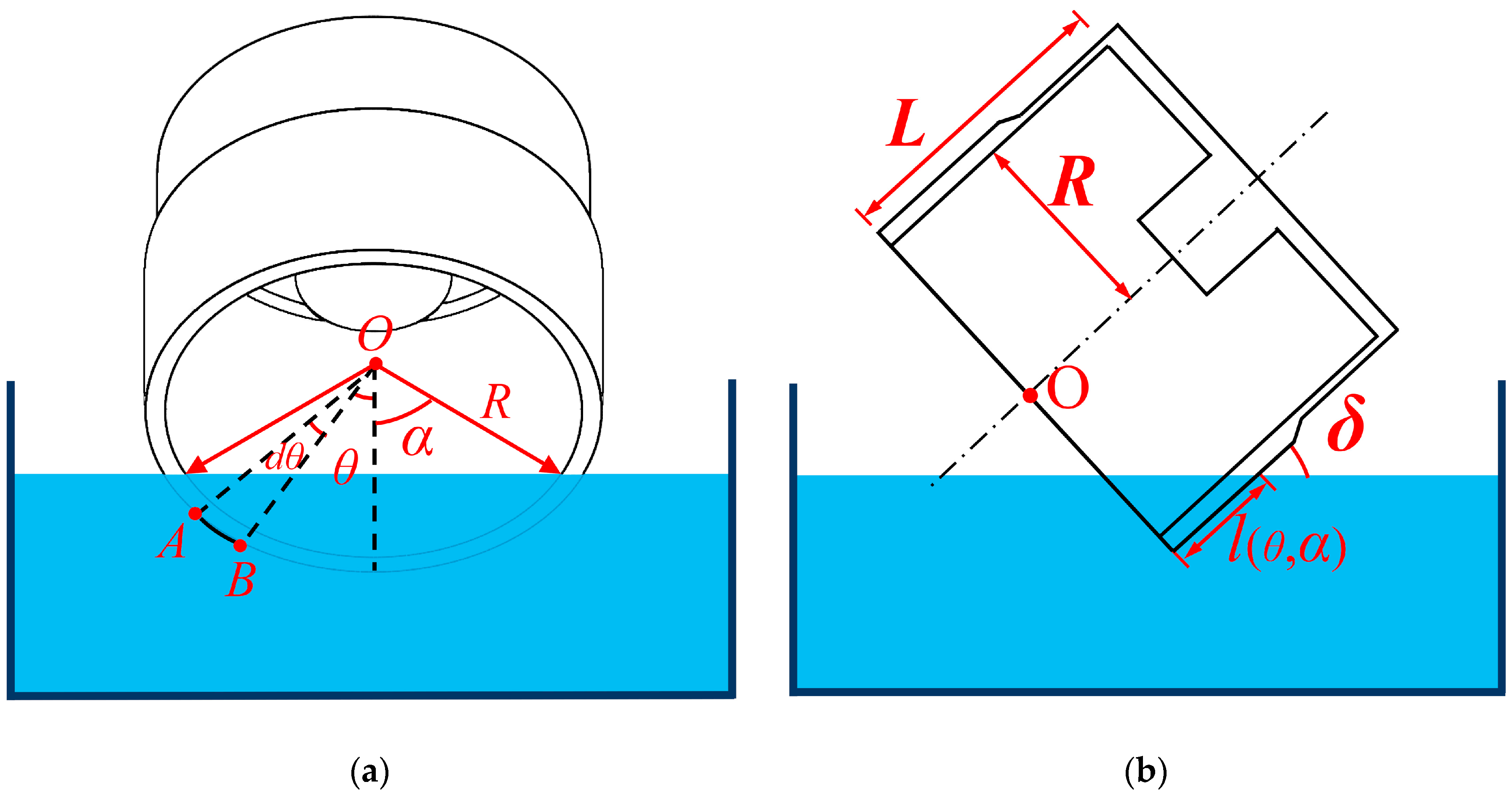
2. Chemical Trimming Principle
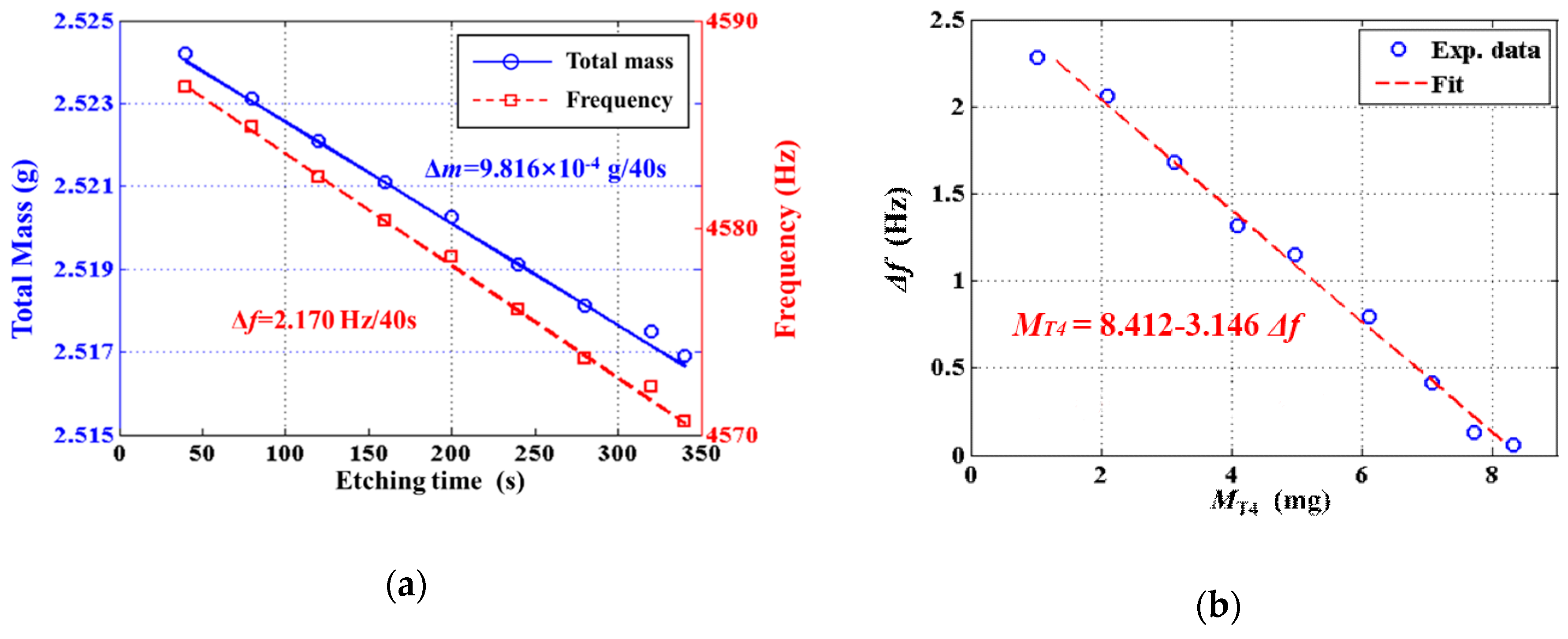
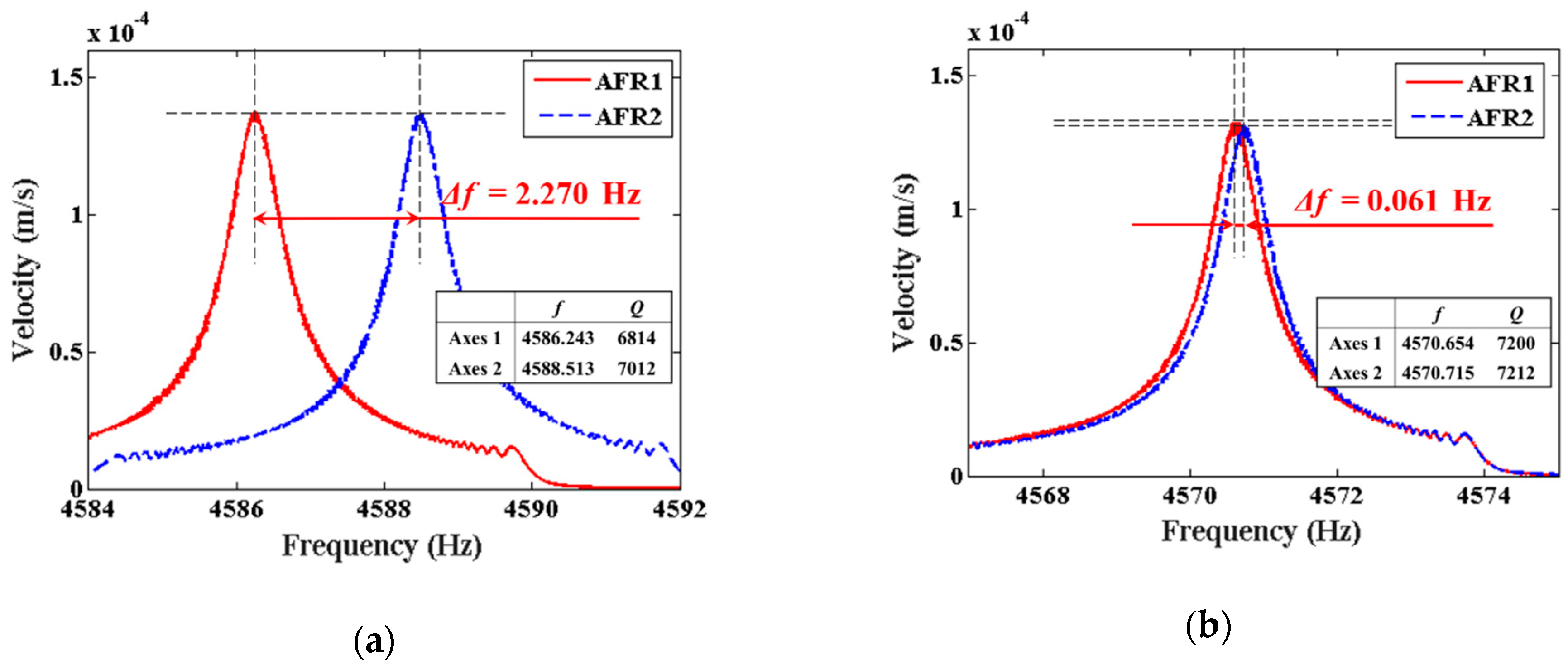
3. Experiment and Results
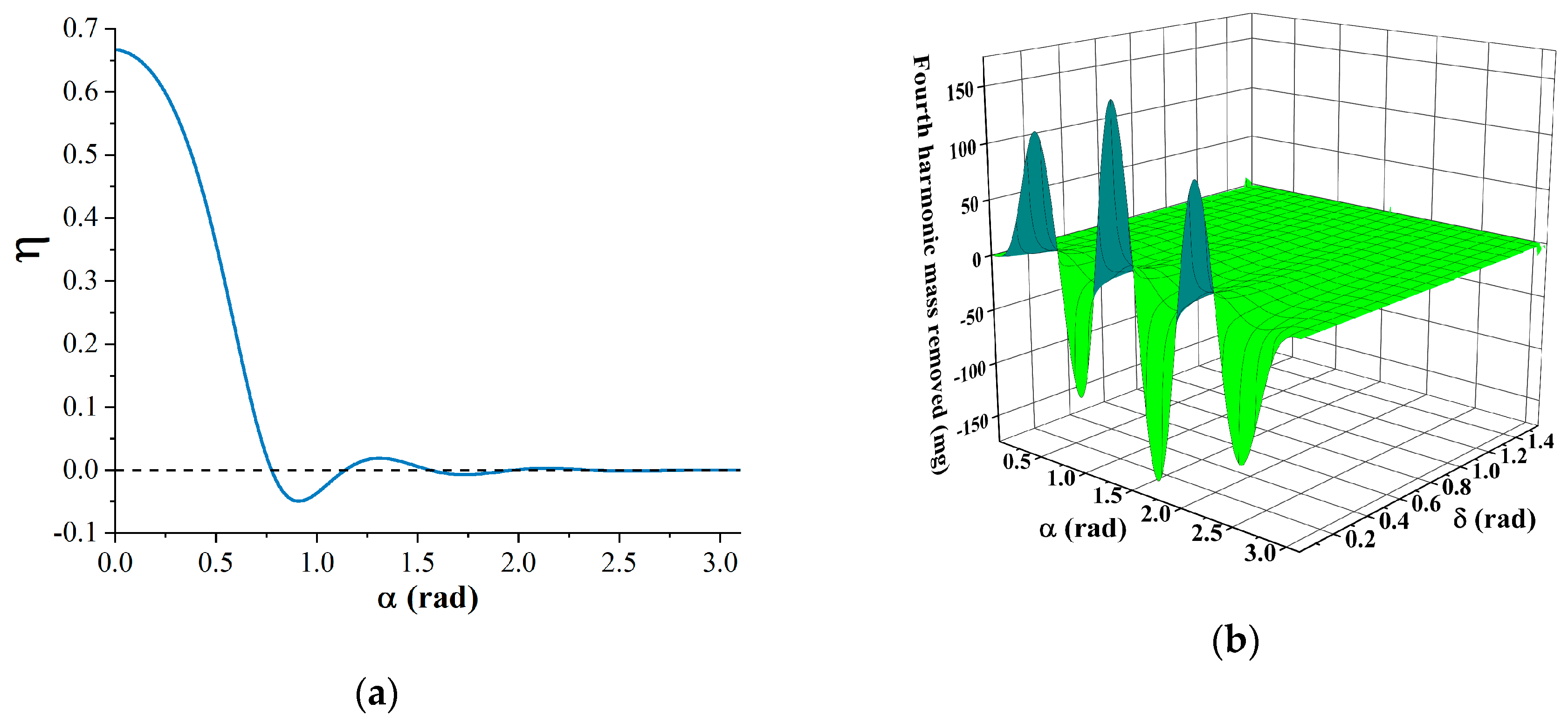
4. Discussions
5. Conclusions
Author Contributions
Funding
Acknowledgments
Conflicts of Interest
Appendix A

References
- Delhaye, F. HRG by SAFRAN: The game-changing technology. In Proceedings of the IEEE International Symposium on Inertial Sensors and Systems (INERTIAL), Milan, Italy, 26–29 March 2018; pp. 1–4. [Google Scholar]
- Rozelle, D.M.; Meyer, A.D.; Trusov, A.A.; Sakaida, D.K. In Milli-HRG inertial sensor assembly-a reality. In Proceedings of the IEEE International Symposium on Inertial Sensors and Systems (ISISS), Hapuna Beach, HI, USA, 23–26 March 2015; pp. 1–4. [Google Scholar]
- Jeanroy, A.; Bouvet, A.; Remillieux, G. HRG and marine applications. Gyroscopy. Navig. 2014, 5, 67–74. [Google Scholar] [CrossRef]
- Rozelle, D. The Hemispherical Resonator Gyro: From Wineglass to the Planets. In Proceedings of the 19th AAS/AIAA Space Flight Mechanics Meeting, Savannah, GA, USA, 8–12 February 2009; pp. 1157–1178. [Google Scholar]
- Delhaye, F.; Girault, J.P. SpaceNaute®® HRG technological breakthrough for advanced space launcher inertial reference system. In Proceedings of the 25th Saint Petersburg International Conference on Integrated Navigation Systems, St. Petersburg, Russia, 28–30 May 2018; pp. 1–5. [Google Scholar]
- Chikovani, V.V.; Okon, I.M.; Barabashov, A.S.; Tewksbury, P. In A set of high accuracy low cost metallic resonator CVG. In Proceedings of the IEEE/ION Position, Location and Navigation Symposium (PLANS ’08), Monterey, CA, USA, 6–8 May 2008; pp. 238–243. [Google Scholar]
- Pan, Y.; Wang, D.; Wang, Y.; Liu, J.; Wu, S.; Qu, T.; Yang, K.; Luo, H. Monolithic Cylindrical Fused Silica Resonators with High Q Factors. Sensors 2016, 16, 1185. [Google Scholar] [CrossRef] [PubMed]
- Pan, Y.; Qu, T.; Wang, D.; Wu, S.; Liu, J.; Tan, Z.; Yang, K.; Luo, H. Observation and analysis of the quality factor variation behavior in a monolithic fused silica cylindrical resonator. Sens. Actuators A Phys. 2017, 260, 81–89. [Google Scholar] [CrossRef]
- Luo, Y.; Qu, T.; Zhang, B.; Pan, Y.; Xiao, P. Simulations and Experiments on the Vibrational Characteristics of Cylindrical Shell Resonator Actuated by Piezoelectric Electrodes with Different Thicknesses. Shock Vib. 2017, 2017, 2314858. [Google Scholar] [CrossRef]
- Fox, C.H.J. A simple theory for the analysis and correction of frequency splitting in slightly imperfect ring. J. Sound Vib. 1990, 142, 227–243. [Google Scholar] [CrossRef]
- Bisegna, P.; Caruso, G. Frequency split and vibration localization in imperfect rings. J. Sound Vib. 2007, 306, 691–711. [Google Scholar] [CrossRef]
- Schwartz, D.; Kim, D.J.; M’Closkey, R.T. Frequency Tuning of a Disk Resonator Gyro Via Mass Matrix Perturbation. J. Dyn. Syst. Meas. Control 2009, 131, 061004. [Google Scholar] [CrossRef]
- Gallacher, B.J.; Hedley, J.; Burdess, J.S.; Harris, A.J.; Rickard, A.; King, D.O. Electrostatic correction of structural imperfections present in a microring gyroscope. J. Microelectromech. Syst. 2005, 14, 221–234. [Google Scholar] [CrossRef]
- Hu, Z.X.; Gallacher, B.J.; Burdess, J.S.; Bowles, S.R.; Grigg, H.T.D. A systematic approach for precision electrostatic mode tuning of a MEMS gyroscope. J. Micromech. Microeng. 2014, 24, 125003. [Google Scholar] [CrossRef]
- Xiao, D.; Yu, D.; Zhou, X.; Hou, Z.; He, H.; Wu, X. Frequency Tuning of a Disk Resonator Gyroscope via Stiffness Perturbation. IEEE Sens. J. 2017, 17, 4725–4734. [Google Scholar] [CrossRef]
- Remillieux, G.; Delhaye, F. In Sagem Coriolis Vibrating Gyros A vision realized. In Proceedings of the DGON Inertial Sensors and Systems (ISS), Karlsruhe, Germany, 16–17 September 2014; pp. 8–21. [Google Scholar]
- Chang, J.; Koh, K.; Min, B.K.; Lee, S.J.; Kim, J.; Lin, L. Synthesis and bidirectional frequency tuning of cantilever-shape nano resonators using a focused ion beam. ACS Appl. Mater. Interfaces 2013, 5, 9684–9690. [Google Scholar] [CrossRef] [PubMed]
- Enderling, S.; Hedley, J.; Jiang, L.; Cheung, R.; Zorman, C.; Mehregany, M.; Walton, A.J. Characterization of frequency tuning using focused ion beam platinum deposition. J. Micromech. Microeng. 2007, 17, 213–219. [Google Scholar] [CrossRef]
- Courcimault, C.G.; Allen, M.G. In High-Q mechanical tuning of MEMS resonators using a metal deposition-annealing technique. In Proceedings of the 13th International Conference on Solid-State Sensors, Actuators and Microsystems, Seoul, Korea, 5–9 June 2005; pp. 875–878. [Google Scholar]
- Wang, Y.; Asadian, M.H.; Shkel, A.M. In Predictive analytical model of fundamental frequency and imperfections in glassblown fused quartz hemi-toroidal 3D micro shells. In Proceedings of the IEEE SENSORS, Orlando, FL, USA, 30 October–3 November 2016; pp. 1–3. [Google Scholar]
- Wang, Y.; Asadian, M.H.; Shkel, A.M. In Frequency split reduction by directional lapping of fused quartz micro wineglass resonators. In Proceedings of the IEEE International Symposium on Inertial Sensors and Systems (INERTIAL), Kauai, HI, USA, 27–30 March 2017; pp. 78–81. [Google Scholar]
- Raspopov, V.Y.; Volchikhin, I.A. In Solid-state wave gyroscope ensuring the required accuracy parameters. In Proceedings of the 25th Saint Petersburg International Conference on Integrated Navigation Systems (ICINS), St. Petersburg, Russia, 28–30 May 2018; pp. 1–3. [Google Scholar]
- Tao, Y.; Xi, X.; Xiao, D.; Tan, Y.; Cui, H.; Wu, X. Precision balance method for cupped wave gyro based on cup-bottom trimming. Chin. J. Micromech. Microeng. 2012, 25, 63–70. [Google Scholar] [CrossRef]
- Zeng, K.; Hu, Y.; Deng, G.; Sun, X.; Su, W.; Lu, Y.; Duan, J. Investigation on Eigenfrequency of a Cylindrical Shell Resonator under Resonator-Top Trimming Methods. Sensors 2017, 17, 2011. [Google Scholar] [CrossRef]
- Lu, K.; Shi, Y.; Xiao, D.; Hou, Z.; Li, W.; Wu, X.; Wu, Y. In Investigation on precise frequency trimming of a micro shell resonator with T-shape masses using low-power femtosecond laser ablation. In Proceedings of the IEEE International Symposium on Inertial Sensors and Systems (INERTIAL), Milan, Italy, 26–29 March 2018; pp. 1–4. [Google Scholar]
- Basarab, M.A.; Lunin, B.S.; Matveev, V.A.; Chumankin, E.A. Balancing of hemispherical resonator gyros by chemical etching. Gyroscopy. Navig. 2015, 6, 218–223. [Google Scholar] [CrossRef]
- Basarab, M.A.; Lunin, B.S.; Matveev, V.A.; Chumankin, E.A. Static balancing of metal resonators of cylindrical resonator gyroscopes. Gyroscopy. Navig. 2014, 5, 213–218. [Google Scholar] [CrossRef]
- Wang, Y.; Pan, Y.; Qu, T.; Jia, Y.; Yang, K.; Luo, H. Decreasing Frequency Splits of Hemispherical Resonators by Chemical Etching. Sensors 2018, 18, 3772. [Google Scholar] [CrossRef] [PubMed]
- Lunin, B.S.; Torbin, S.N.; Danchevskaya, M.N.; Batov, I.V. Influence of the Damaged Surface Layer on the Q of Fused Silica Resonators. Moscow Univ. Chem. Bull. 1994, 35, 24–28. [Google Scholar]
- Lunin, B.S.; Torbin, S.N.; Danachevskaya, M.N.; Batov, I.V. On the mechanism of acoustic losses in the hydroxylated surface layer of silica glass. Moscow Univ. Chem. Bull. 2001, 56, 19–22. [Google Scholar]
- Fan, C. Axisysmmetric Shell Resonator Gyroscopes; National Defense Industry Press: Beijing, China, 2013; pp. 25–34. [Google Scholar]
- Soedel, W. Vibrations of Shells and Plates (3rd Edition, Revised and Expanded); Marcel Dekker: New York, NY, USA, 2004; pp. 157–159. [Google Scholar]


| Resonator | Before Etching | After Etching | ||||||
|---|---|---|---|---|---|---|---|---|
| f1 (Hz) | Δf (Hz) | Q1 | δQ (%) | f1 (Hz) | Δf (Hz) | Q1 | δQ (%) | |
| #I01 | 4586.243 | 2.270 | 6814 | 2.864 | 4570.654 | 0.061 | 7200 | 0.167 |
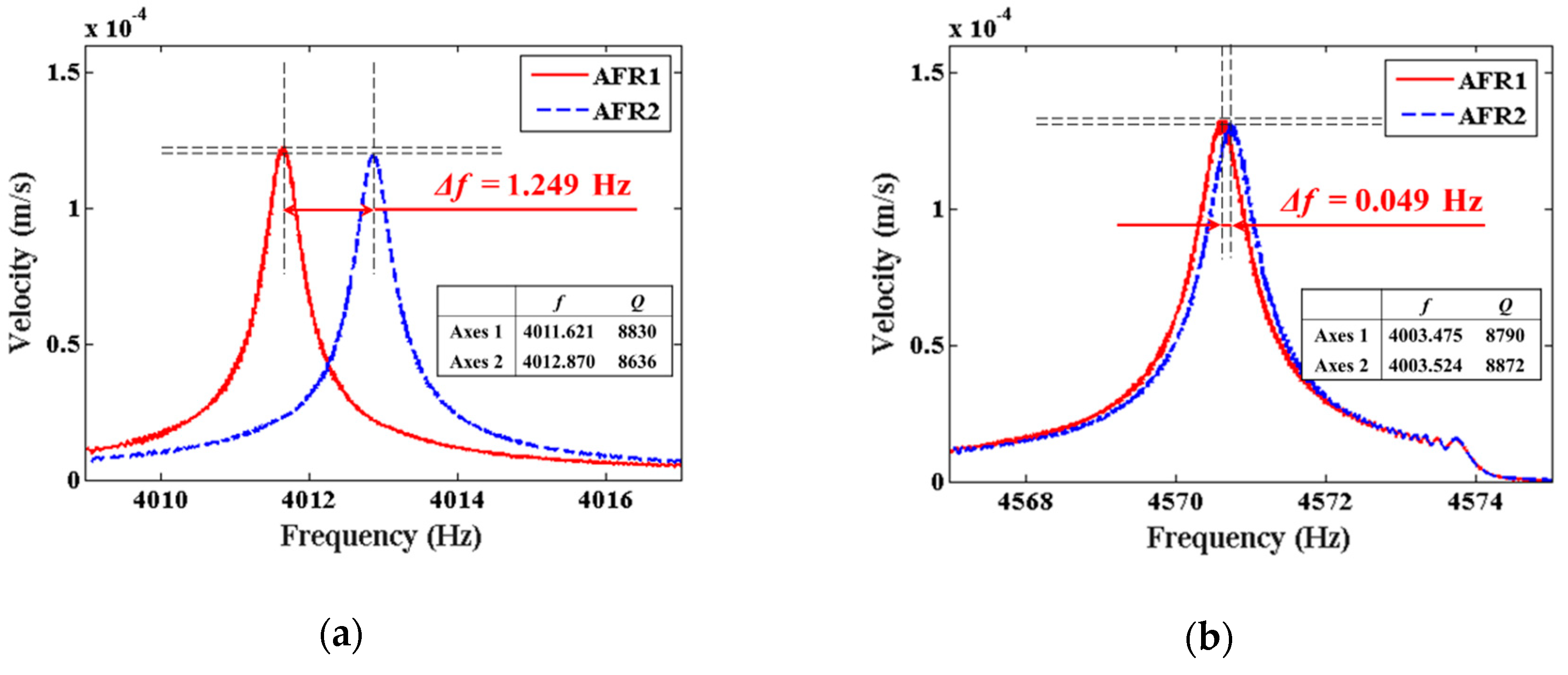
| #I02 | 4011.621 | 1.249 | 8830 | 2.221 | 4003.475 | 0.049 | 8790 | 0.929 |
| #I03 | 3961.133 | 1.318 | 8696 | 0.825 | 3954.773 | 0.061 | 9143 | 0.207 |
© 2019 by the authors. Licensee MDPI, Basel, Switzerland. This article is an open access article distributed under the terms and conditions of the Creative Commons Attribution (CC BY) license (http://creativecommons.org/licenses/by/4.0/).
Share and Cite
Tao, Y.; Pan, Y.; Jin, S.; Jia, Y.; Yang, K.; Luo, H. Trimming of Imperfect Cylindrical Fused Silica Resonators by Chemical Etching. Sensors 2019, 19, 3596. https://doi.org/10.3390/s19163596
Tao Y, Pan Y, Jin S, Jia Y, Yang K, Luo H. Trimming of Imperfect Cylindrical Fused Silica Resonators by Chemical Etching. Sensors. 2019; 19(16):3596. https://doi.org/10.3390/s19163596
Chicago/Turabian StyleTao, Yunfeng, Yao Pan, Shilong Jin, Yonglei Jia, Kaiyong Yang, and Hui Luo. 2019. "Trimming of Imperfect Cylindrical Fused Silica Resonators by Chemical Etching" Sensors 19, no. 16: 3596. https://doi.org/10.3390/s19163596
APA StyleTao, Y., Pan, Y., Jin, S., Jia, Y., Yang, K., & Luo, H. (2019). Trimming of Imperfect Cylindrical Fused Silica Resonators by Chemical Etching. Sensors, 19(16), 3596. https://doi.org/10.3390/s19163596