Analysis of Beamforming Antenna for Practical Indoor Location-Tracking Application


Abstract
:1. Introduction
2. Antenna Design and Analysis
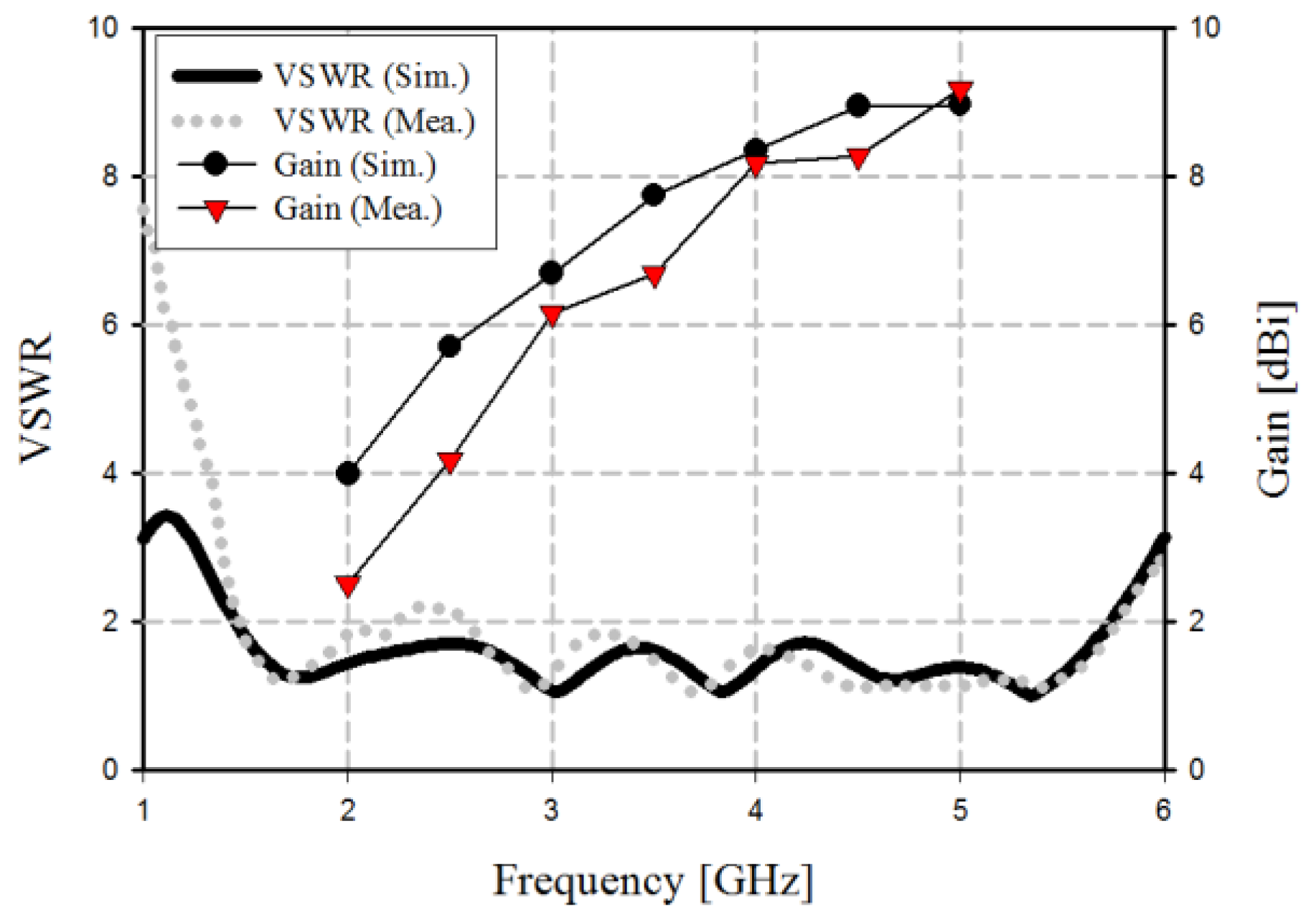
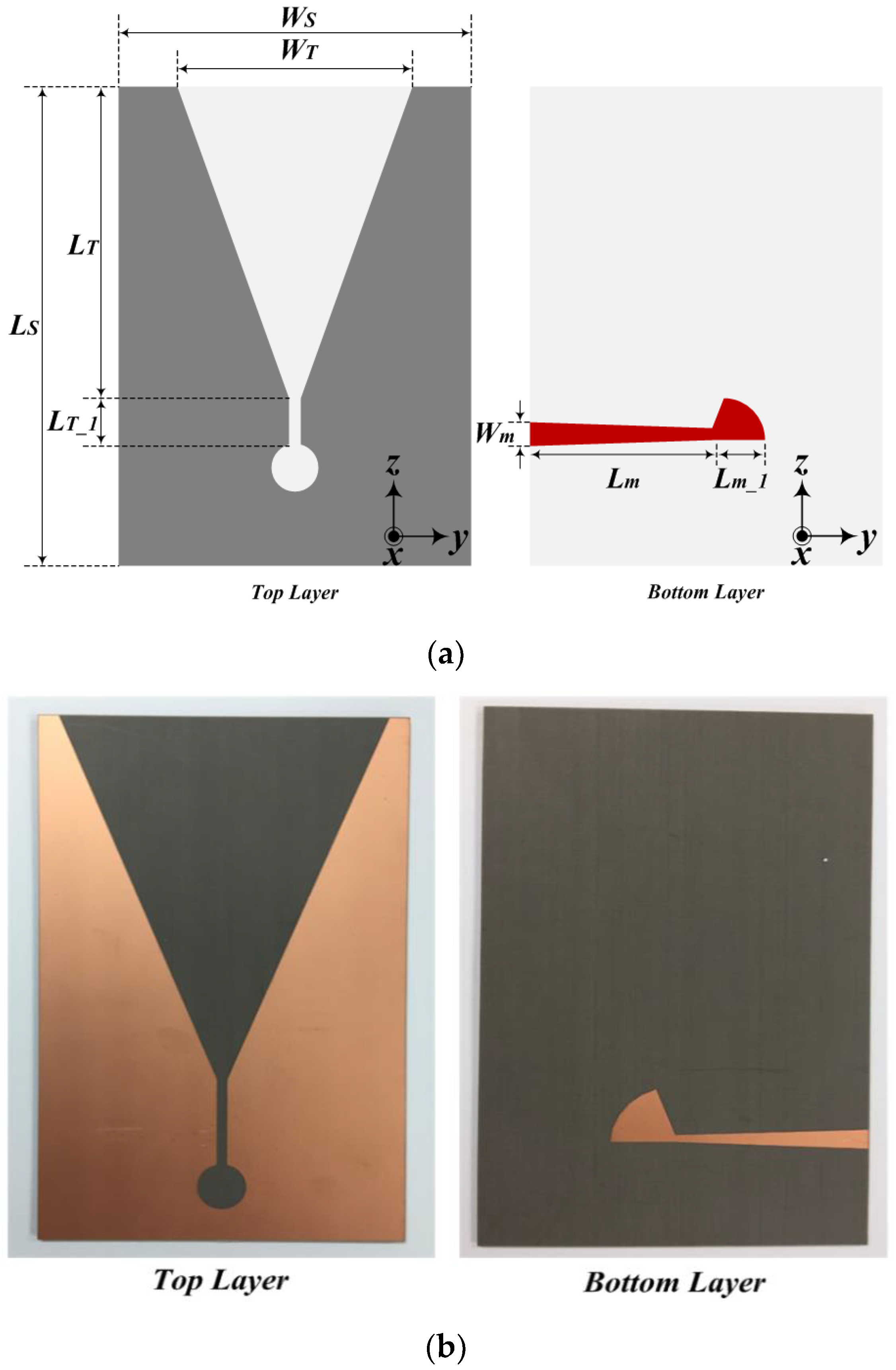
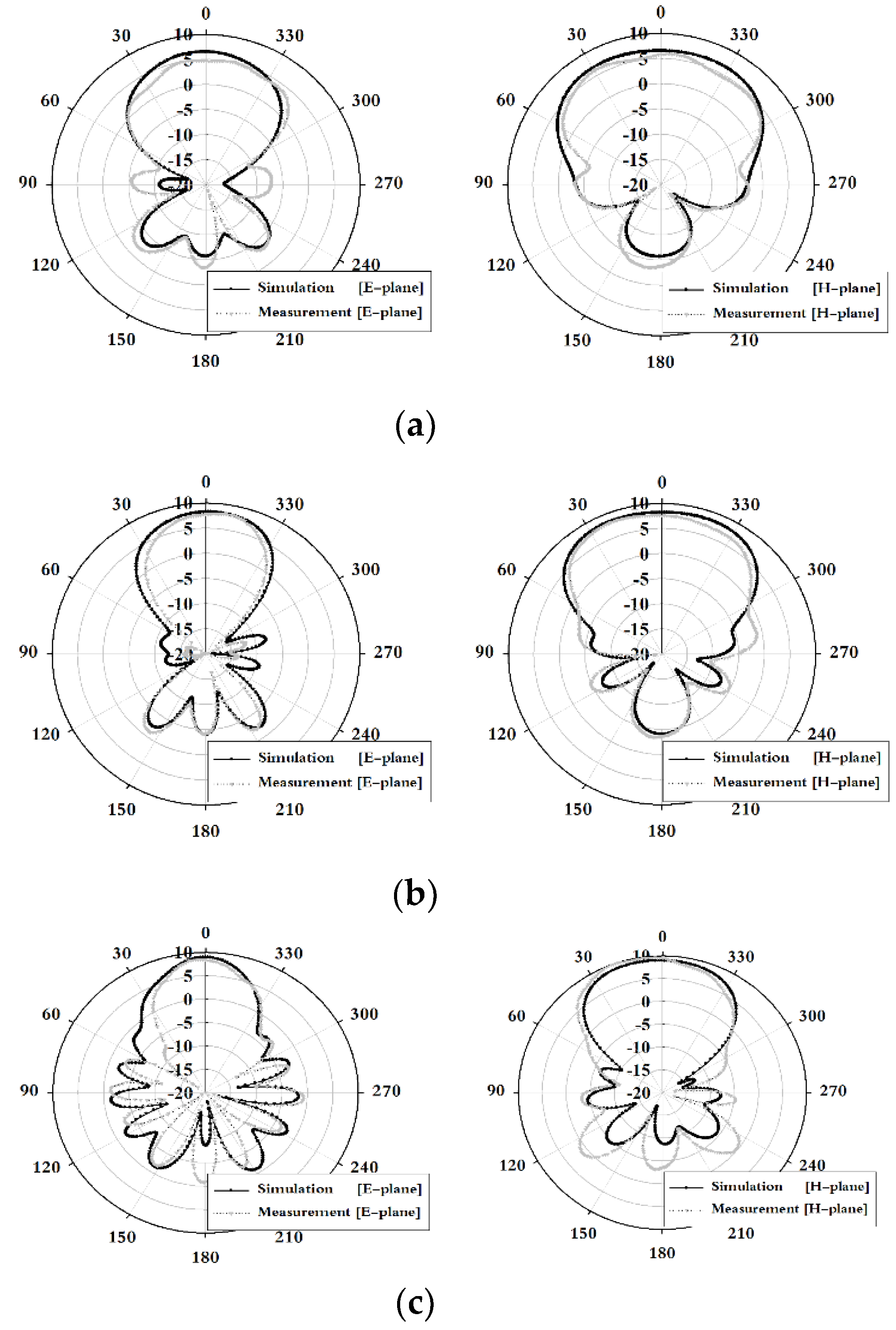
2.1. Design and Measurement of Tapered Slot Antenna (TSA)
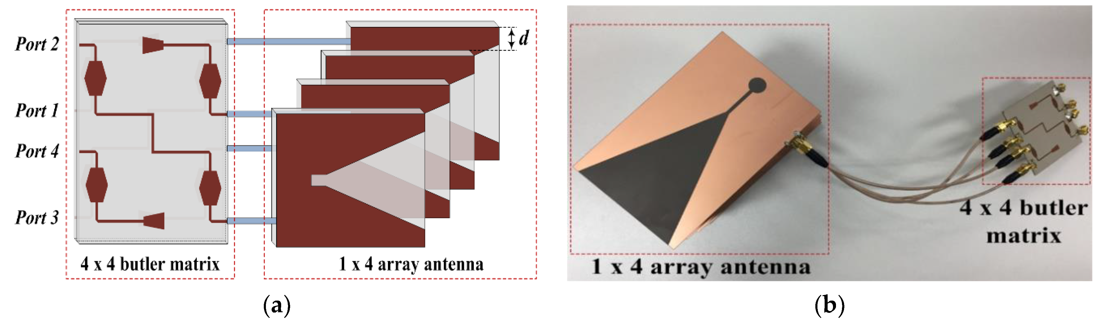
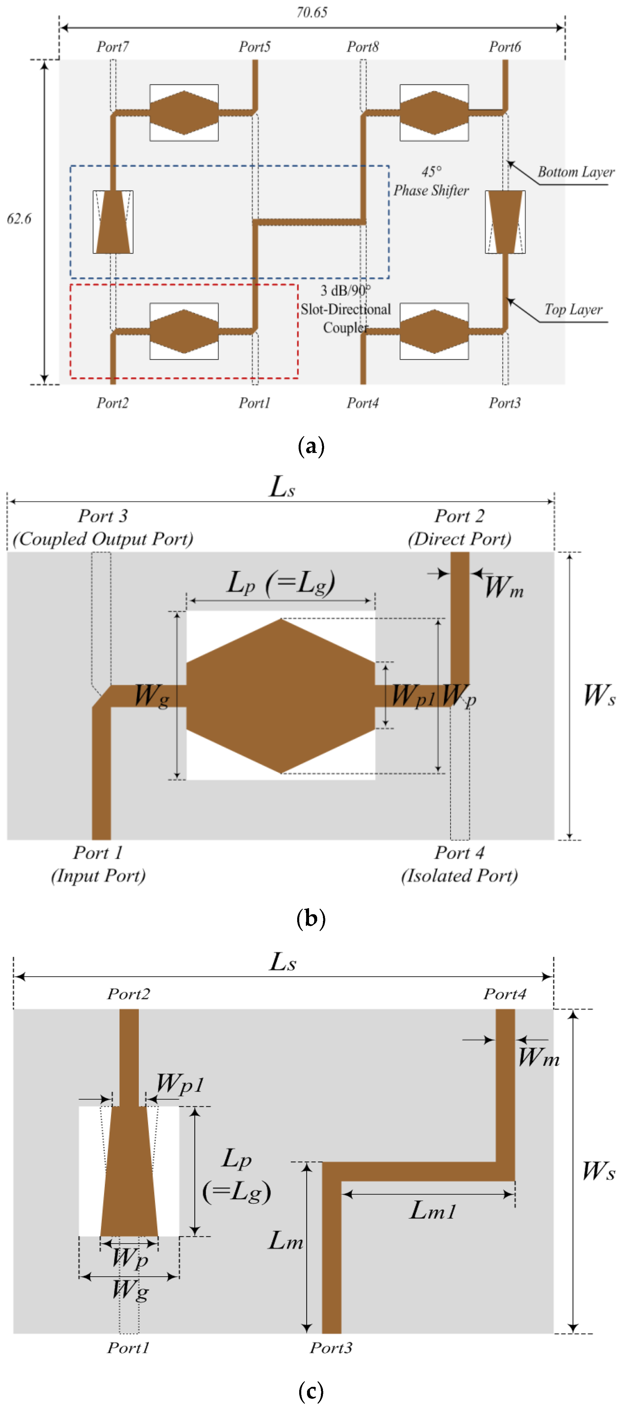
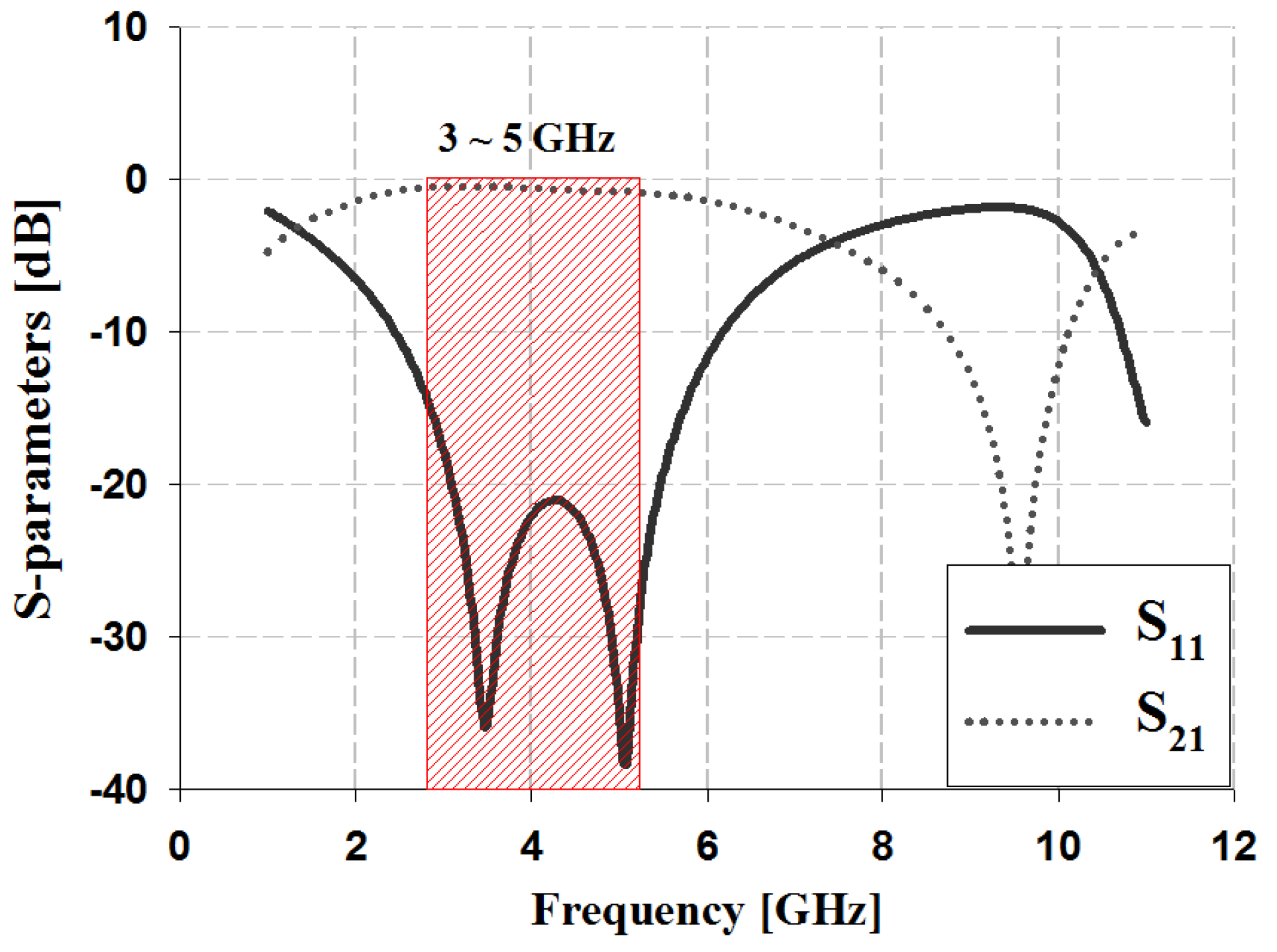
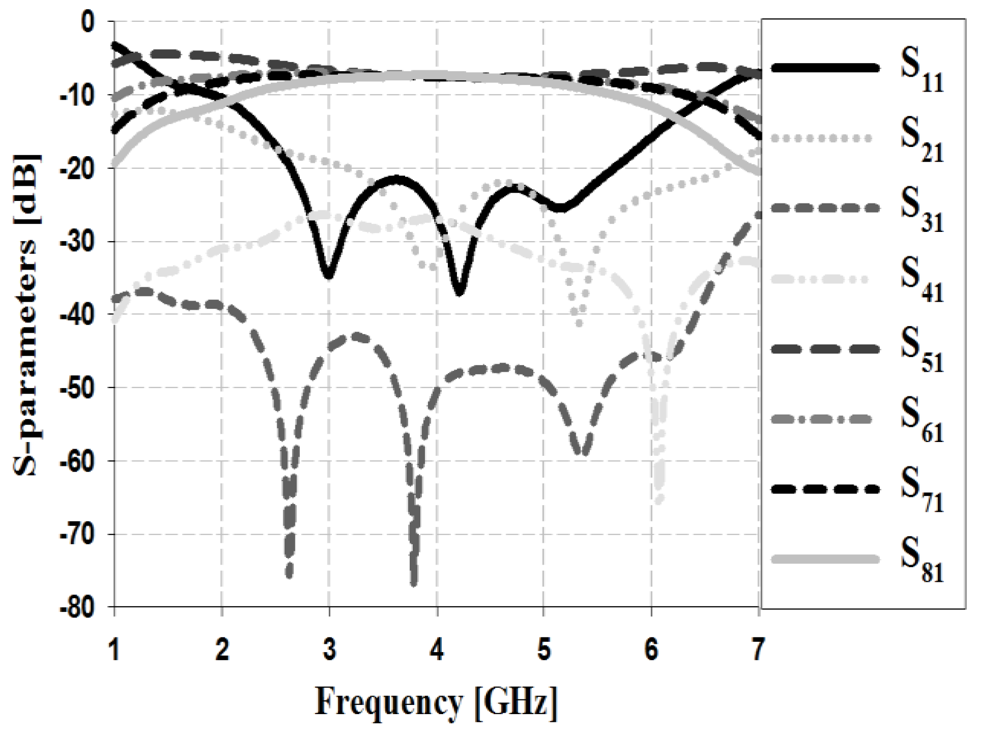
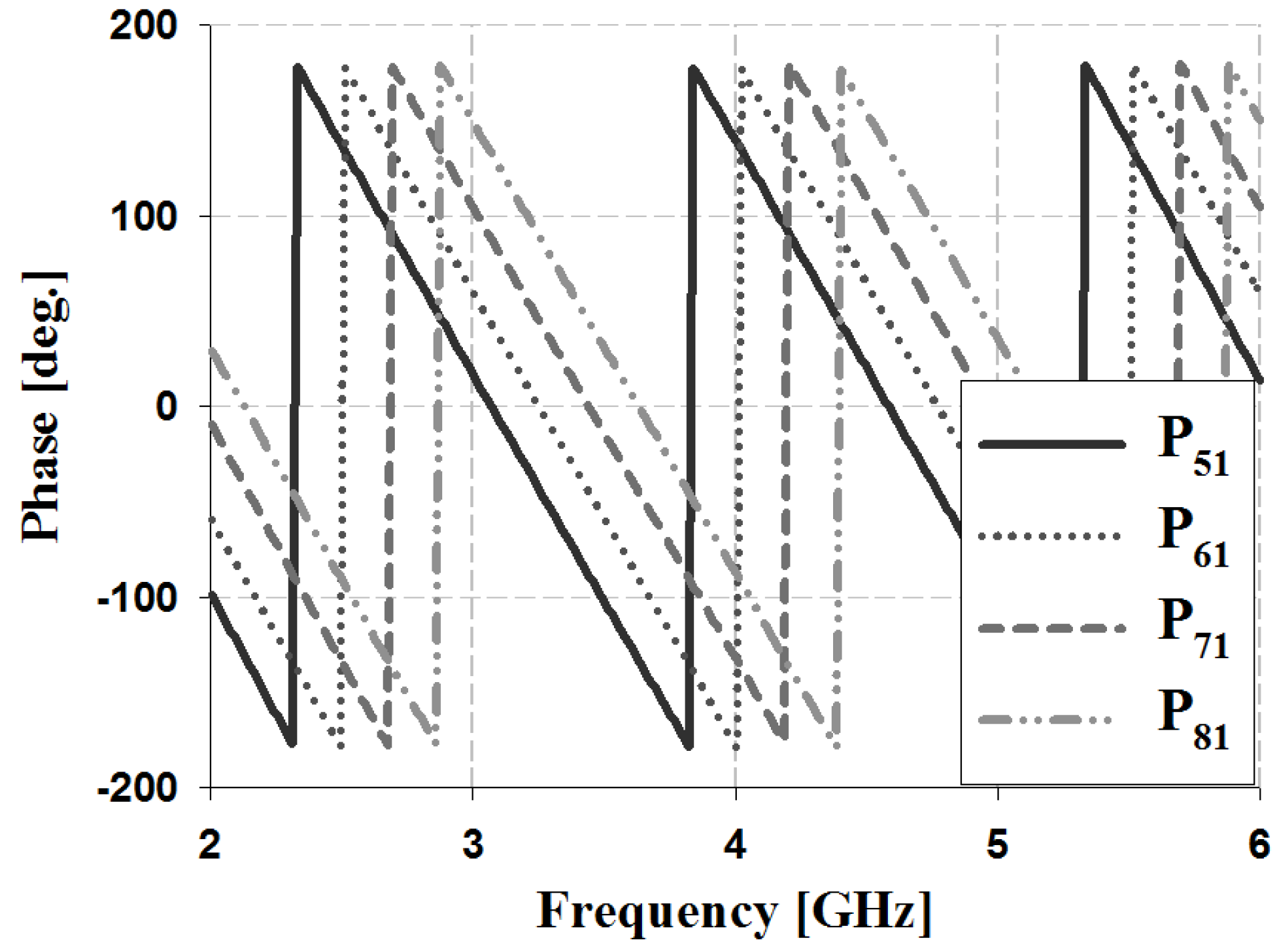
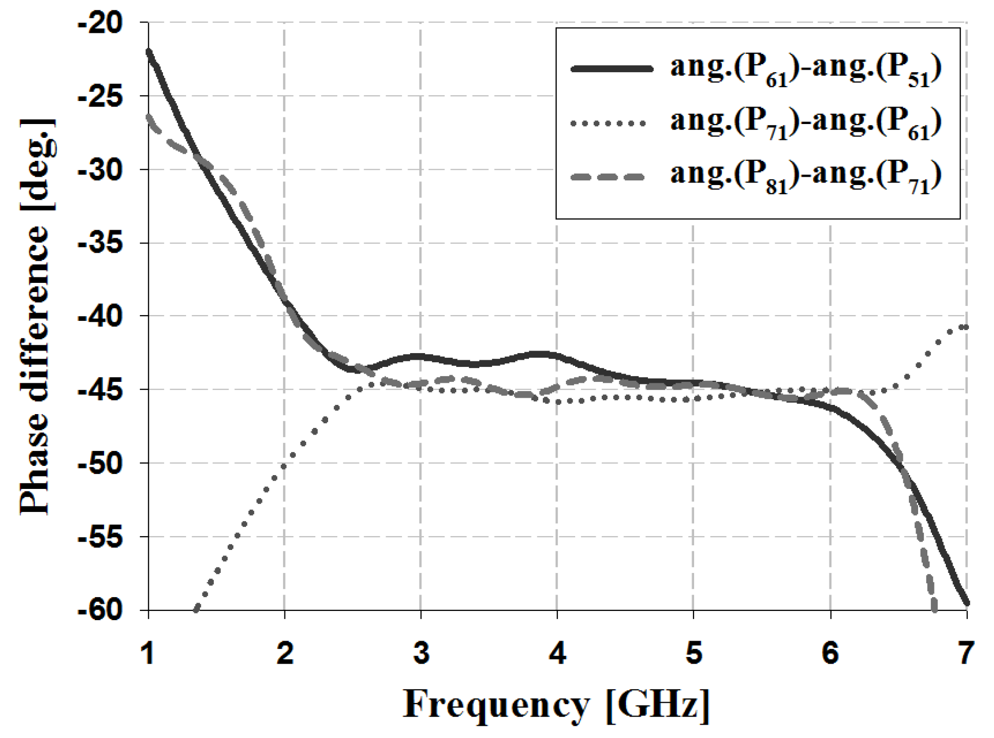
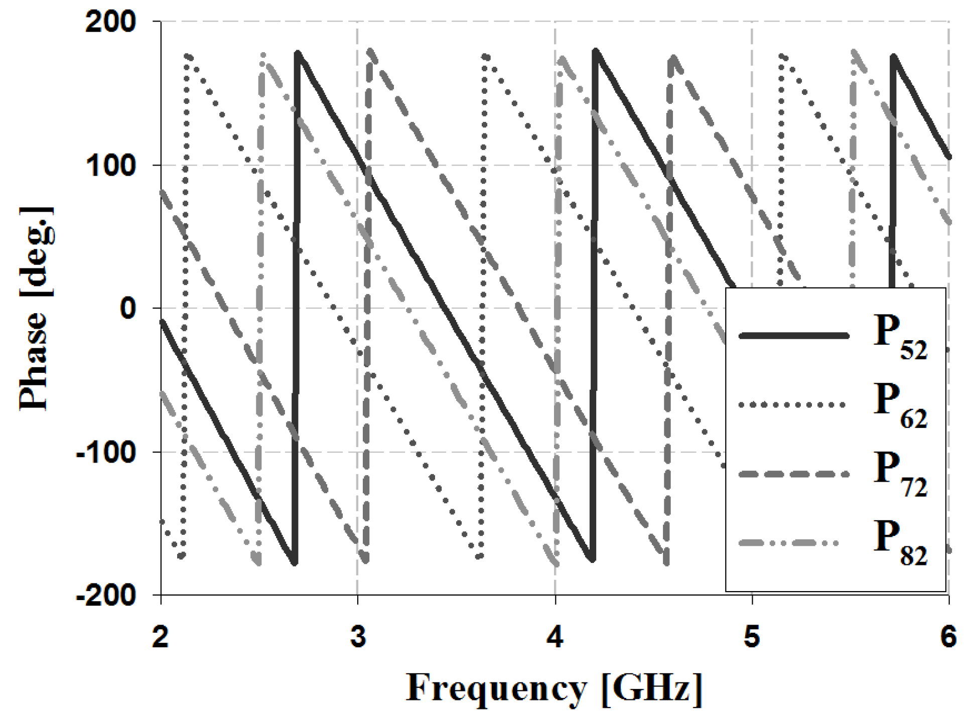
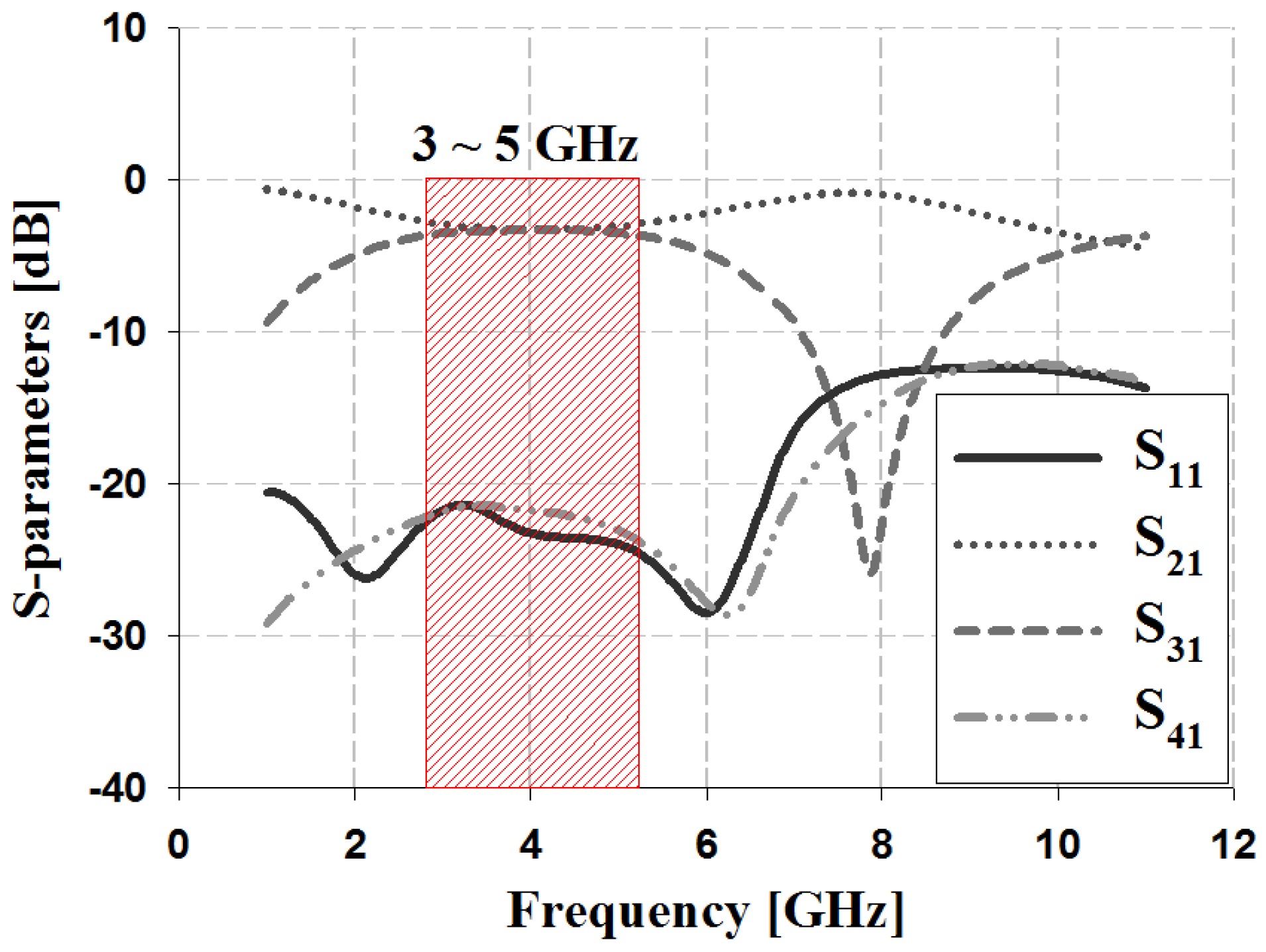
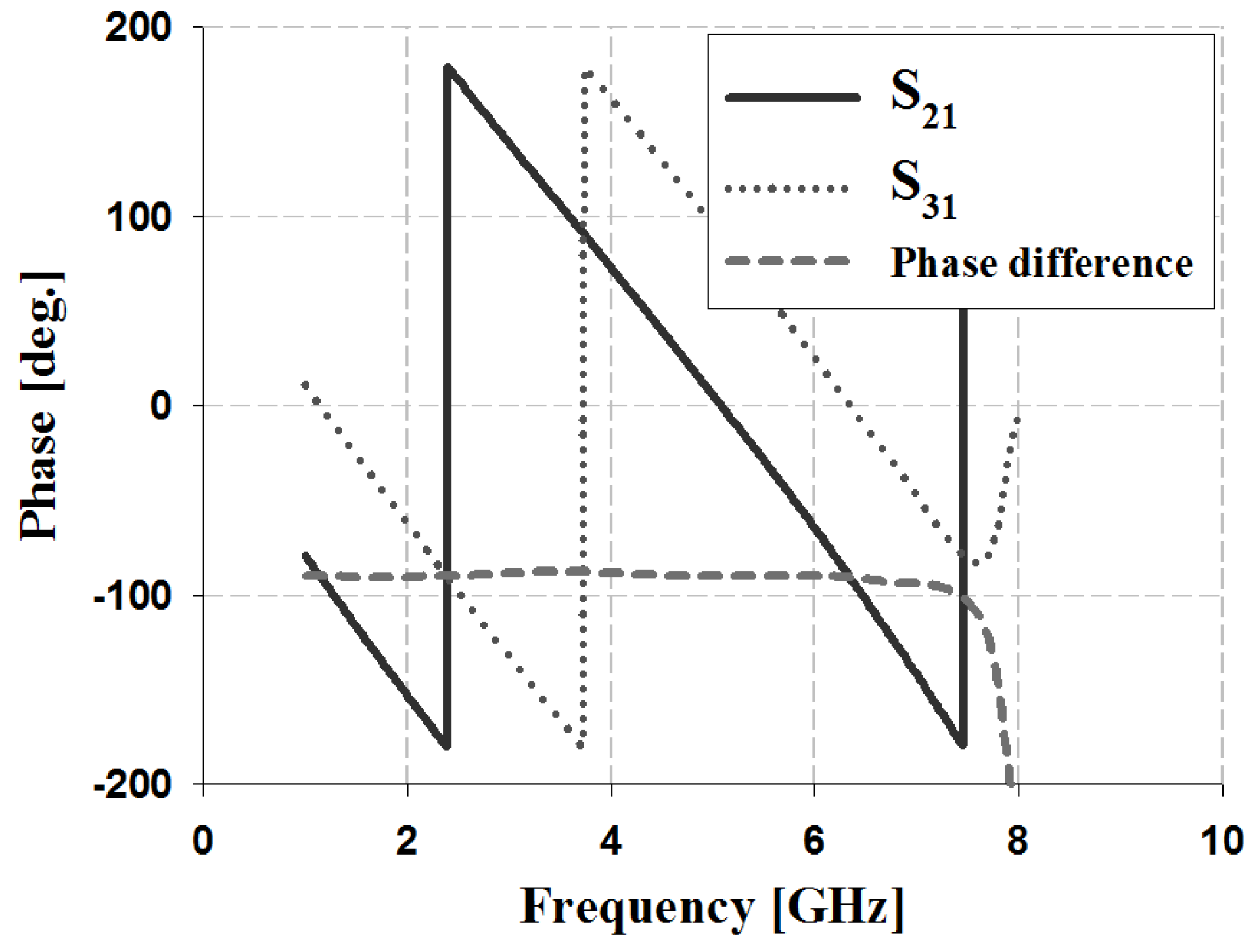
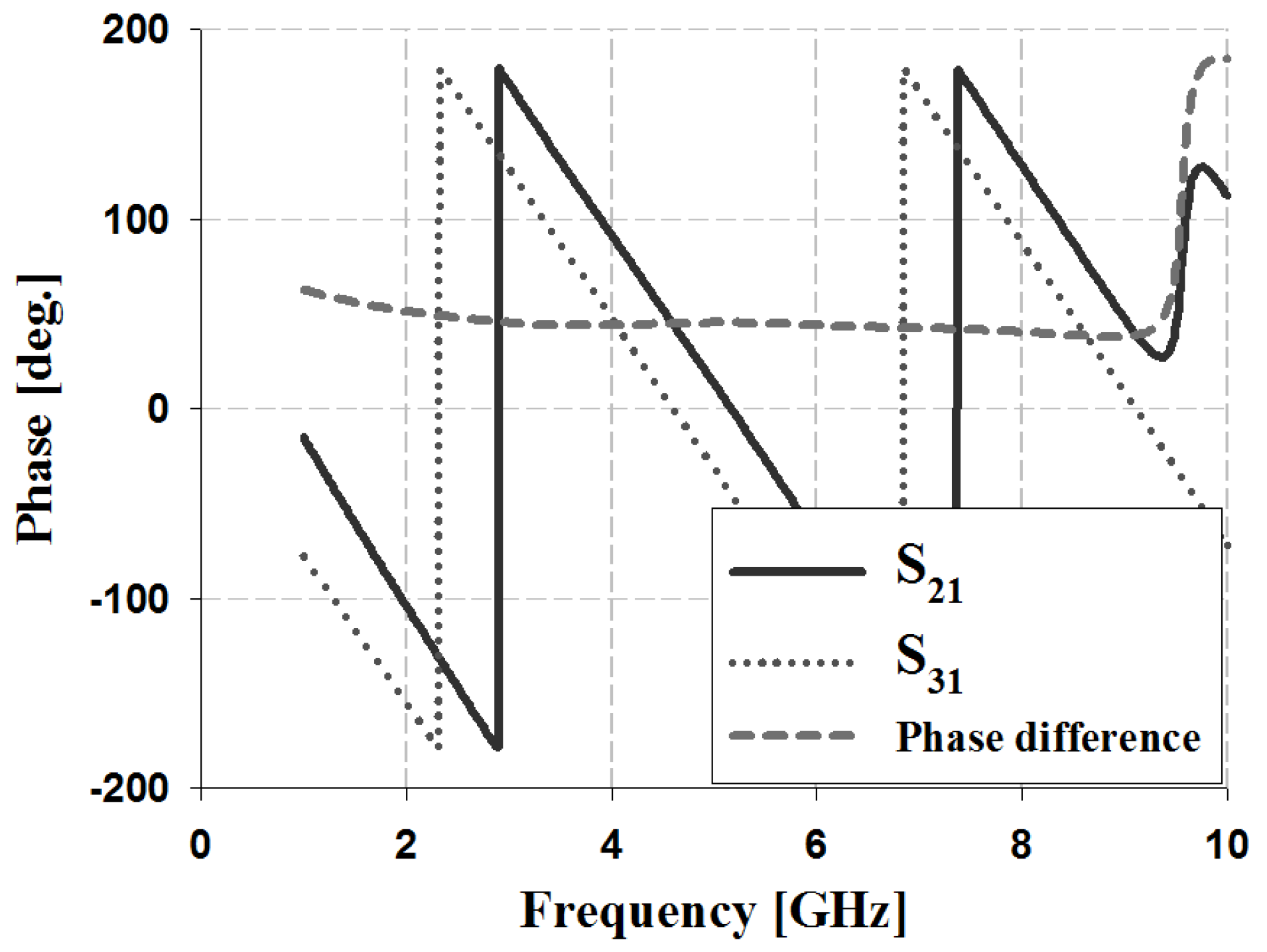
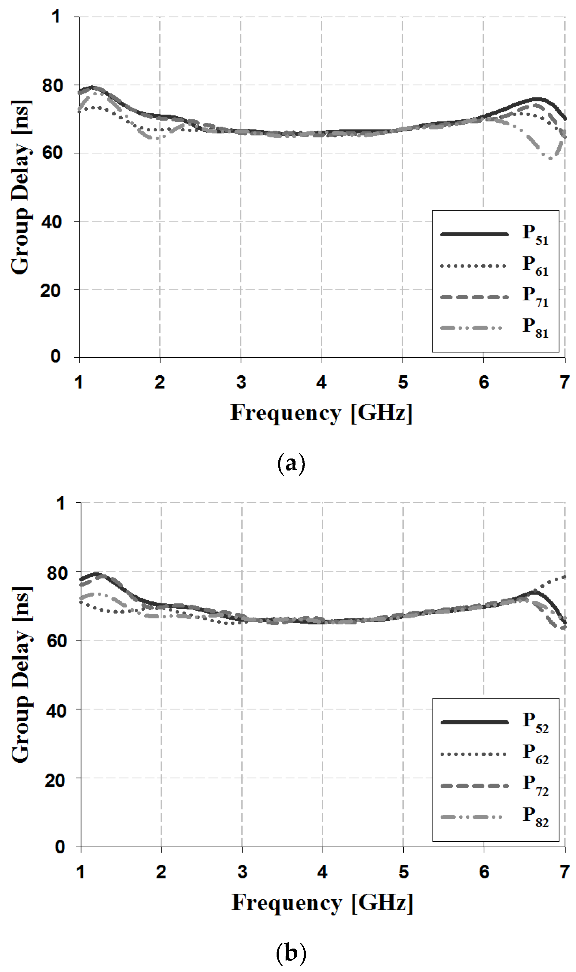
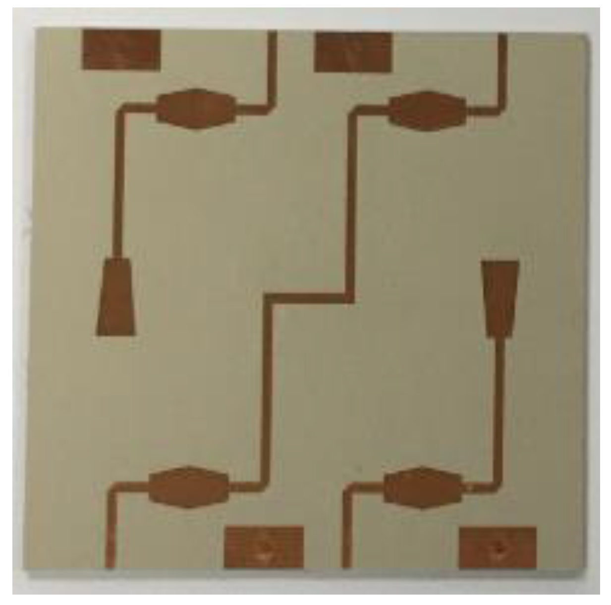
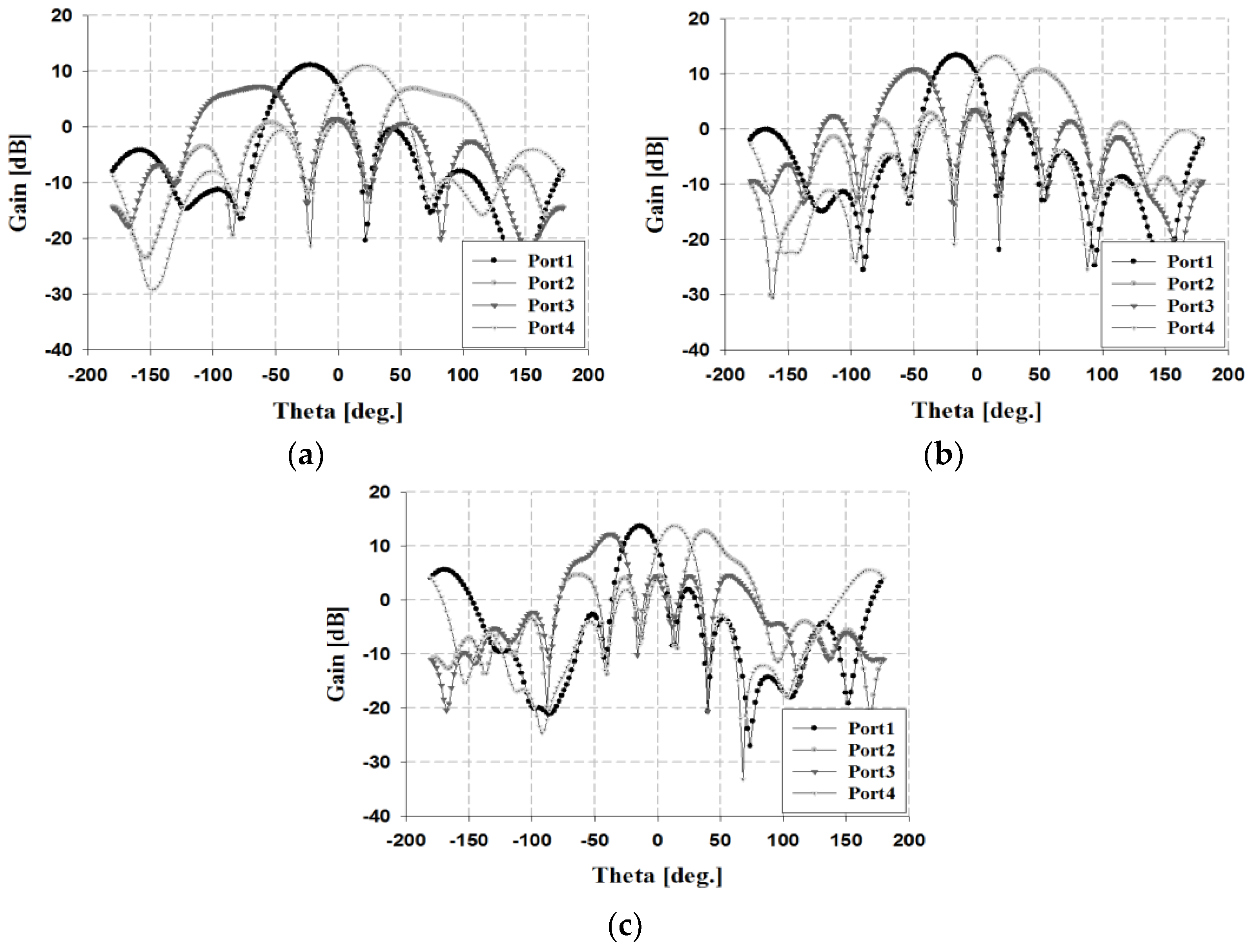
2.2. Design and Measurement of Butler Matrix
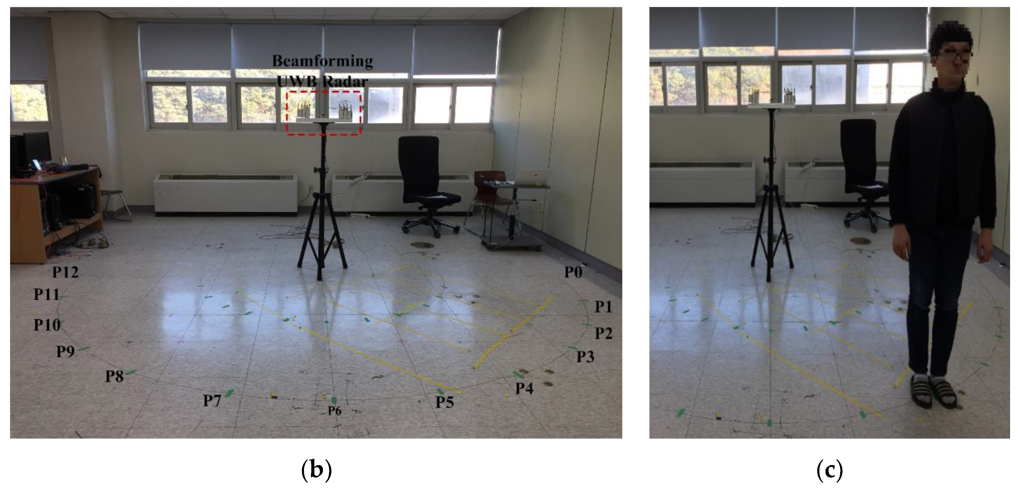
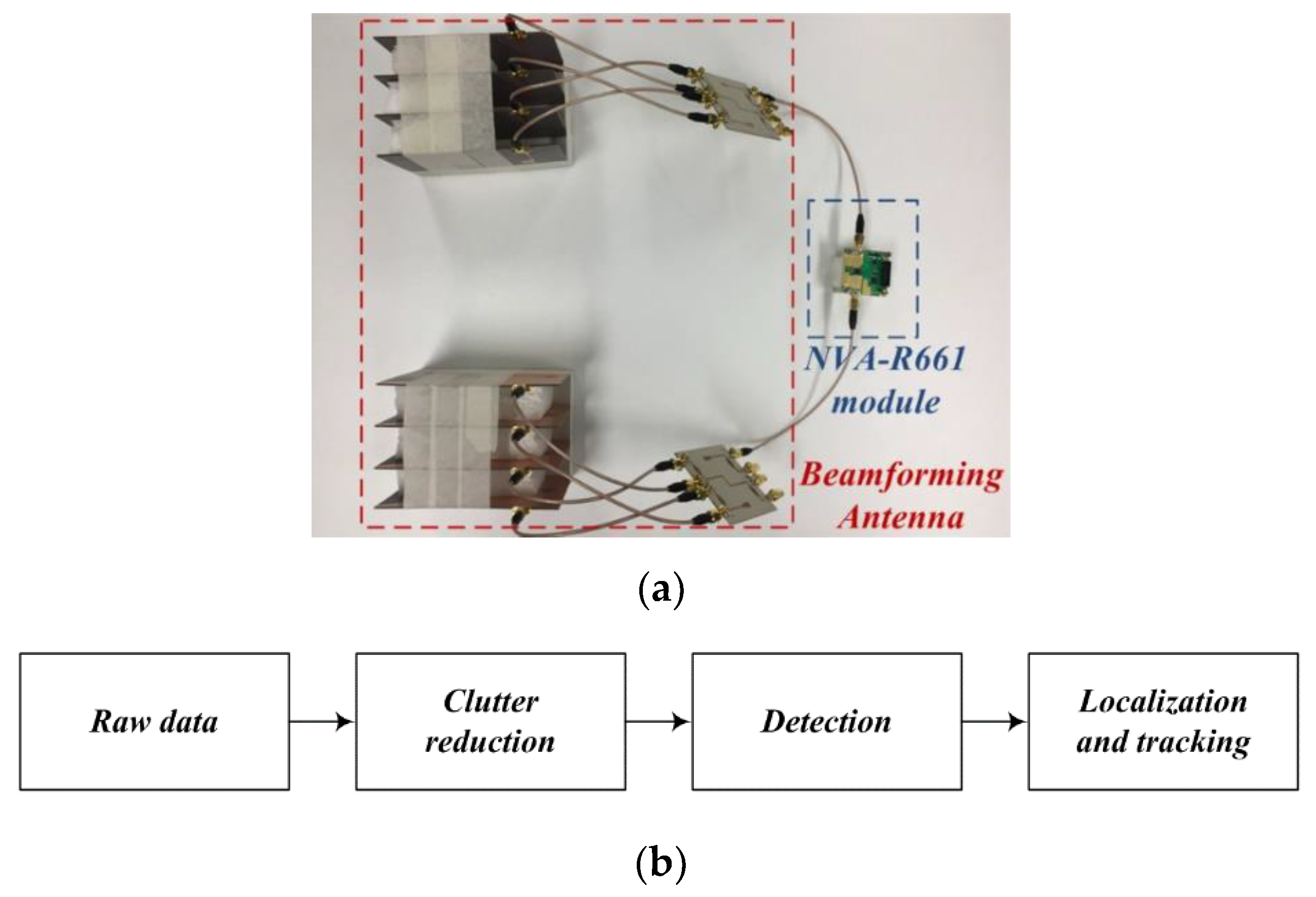
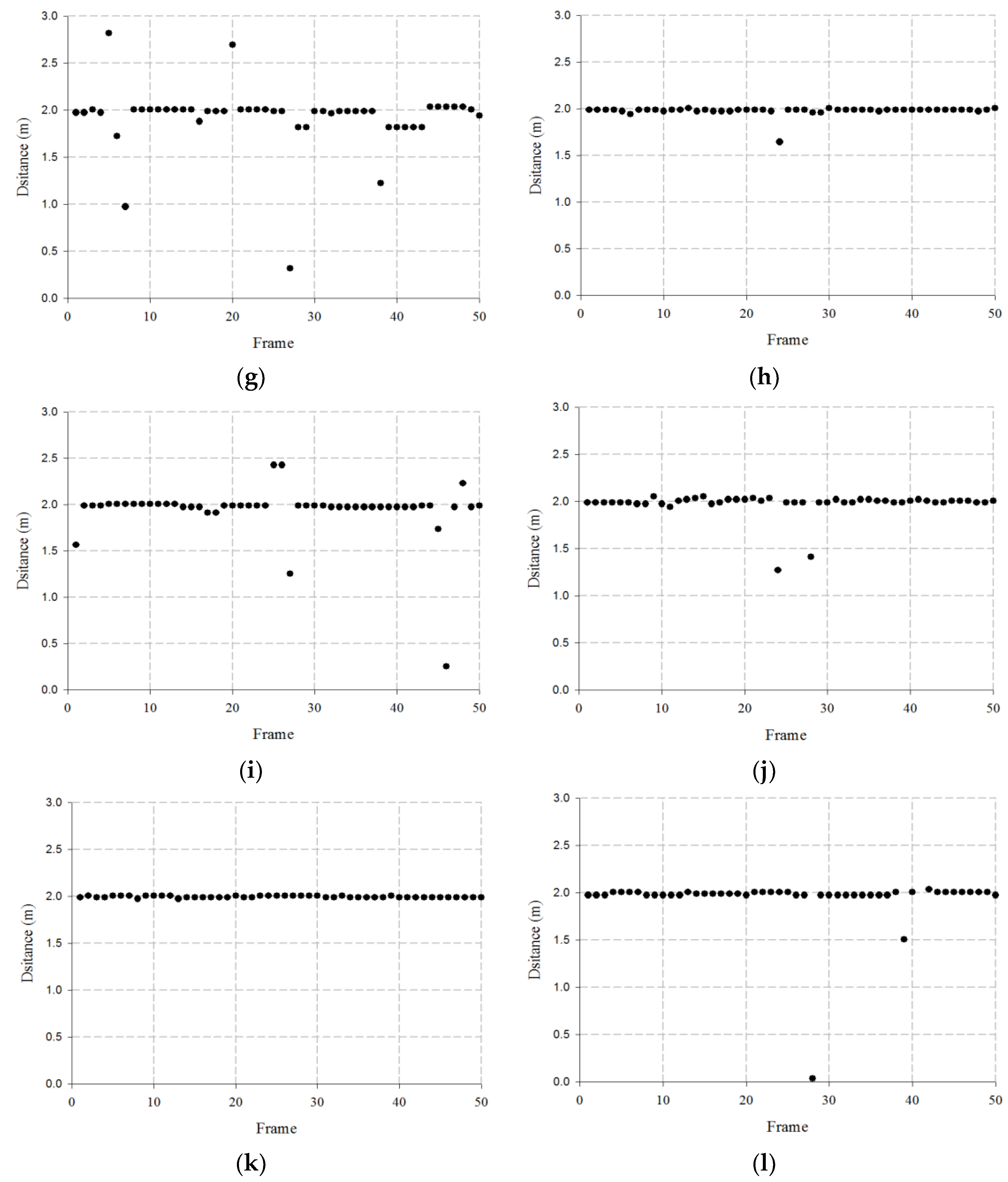
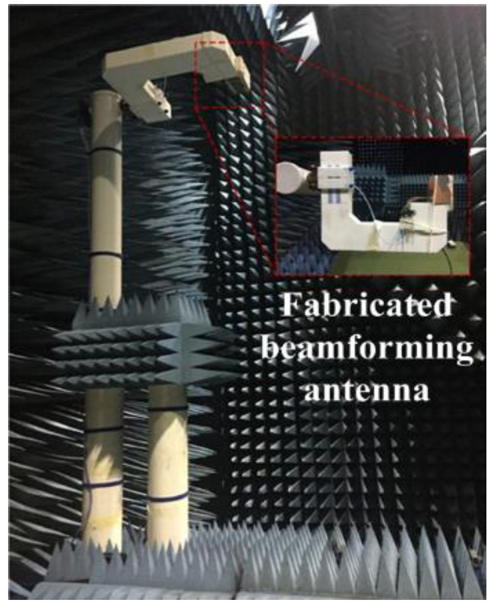
3. Target Tracking Test of Fabricated Beamforming Antenna
Test of Indoor Location Tracking for Beamforming Antenna
4. Conclusions
Author Contributions
Funding
Conflicts of Interest
References
- Kim, S.W. Implementation of Beamforming Antenna for UWB Radar Using Butler Matrix. Ph.D. Thesis, Department of Information and Communication Engineering Chosun University, Gwangju, Korea, 2018. [Google Scholar]
- Wang, Z.; Yin, Y.; Wu, J.; Lian, R. A Miniaturized CPW-Fed Antipodal Vivaldi Antenna with Enhanced Radiation Performance for Wideband Applications. IEEE Antennas Wirel. Propag. Lett. 2016, 15, 16–19. [Google Scholar] [CrossRef]
- Yang, Z.; Huang, J.; Wu, W.; Yuan, N. An antipodal Vivaldi antenna with band-notched characteristics for ultra-wideband applications. Int. J. Electron. Commun. 2017, 76, 152–157. [Google Scholar] [CrossRef]
- Rabbani, M.S.; Ghafouri-Shiraz, H. Accurate remote vital sign monitoring with 10 GHz ultra-wide patch antenna array. Int. J. Electron. Commun. 2017, 77, 36–42. [Google Scholar] [CrossRef]
- Wu, J.; Zhao, Z.; Nie, Z.; Liu, Q.H. Bandwidth Enhancement of a Planar Printed Quasi-Yagi Antenna with Size Reduction. IEEE Trans. Antennas Propag. 2014, 62, 463–467. [Google Scholar] [CrossRef]
- Yang, D.; Qu, J.; Zhao, Z.; Liu, S.; Nie, Z. Planar quasi-Yagi antenna with band rejection based on dual dipole structure for UWB. IET Microw. Antennas Propag. 2016, 10, 1708–1714. [Google Scholar] [CrossRef]
- Zhu, F.; Gao, S.; Ho, A.T.S.; See, C.H.; Abd-Alhameed, R.A.; Li, J.; Xu, J. Dual band-notched tapered slot antenna using λ/4 band-stop filters. IET Microw. Antennas Propag. 2012, 6, 1665–1673. [Google Scholar] [CrossRef]
- Chagharvand, S.; Hamid, R.M.; Kamarudin, R.M.; Ghanem, F. Reconfigurable Multiband Tapered Slot Antenna. Microw. Opt. Technol. Lett. 2015, 57, 2182–2186. [Google Scholar] [CrossRef]
- Haraz, O.M.; Sebak, A.B.; Alshebeili, A.S. Ultra-Wideband 4 × 4 Butler Matrix Employing Trapezoidal-Shaped Microstrip-Slot Technique. Wirel. Pers. Commun. 2015, 82, 2015. [Google Scholar] [CrossRef]
- Nie, W.; Fan, Y.; Luo, S.; Guo, Y. A switched-beam microstrip antenna array with miniaturized butler matrix network. Microw. Opt. Technol. Lett. 2014, 57, 841–845. [Google Scholar] [CrossRef]
- Schaubert, D.; Kollberg, E.; Korzeniowski, T.; Thungren, T.; Johansson, J.; Yngvesson, K. Endfire tapered slot antennas on dielectric substrates. IEEE Trans. Antennas Propag. 1985, 33, 1392–1400. [Google Scholar] [CrossRef]
- XETHRU. UWB Module. Available online: https://www.xethru.com/ (accessed on 11 April 2019).
- Kim, S.W.; Noh, S.K.; Yu, H.G.; Choi, D.Y. Design and Analysis of a Quasi-Yagi Antenna for an Indoor Location Tracking System. Sensors 2018, 18, 4246. [Google Scholar] [CrossRef] [PubMed]
- Verma, P.K.; Gaikwad, A.N.; Singh, D.; Nigam, M.J. Analysis of clutter reduction techniques for through wall imaging in UWB range. Prog. Electromagn. Res. B 2019, 17, 29–48. [Google Scholar] [CrossRef]
- Singh, S.; Liang, Q.; Chen, D.; Sheng, L. Sense through wall human detection using UWB radar. EURASIP J. Wirel. Commun. Netw. 2011, 2011, 1–11. [Google Scholar] [CrossRef]
- Kim, S.W.; Yu, H.G.; Choi, K.W.; Choi, D.Y. Analysis of Tapered Slot Antenna with High Gain for 2D Indoor Wireless Positioning. IEEE Access 2019, 7, 54312–54320. [Google Scholar] [CrossRef]
- Hirata, S.; Kurosawa, M.K.; Katagiri, T. Cross-correlation by single-bit signal processing for ultrasonic distance measurement. IEICE Trans. Fundam. Electron. Commun. Comput. Sci. 2008, 91, 1031–1037. [Google Scholar] [CrossRef]
- Yano, S.M. Investigating the ultra-wideband indoor wireless channel. Proc. IEEE VTC Spring Conf. 2002, 3, 1200–1204. [Google Scholar]
- Shao, J.; Fang, G.; Ji, Y.; Tan, K.; Yin, H. A novel compact tapered-slot antenna for GPR applications. IEEE Antennas Wirel. Propag. Lett. 2013, 12, 972–975. [Google Scholar] [CrossRef]
- Kim, B.-H.; Han, S.-J.; Kwon, G.-R.; Pyun, J.-Y. Signal processing for tracking of moving object in multi-impulse radar network system. Int. J. Distrib. Sens. Netw. 2015, 11, 536841. [Google Scholar] [CrossRef]


| Parameters | Simulation Results | Measurement Results | ||||
|---|---|---|---|---|---|---|
| Impedance bandwidth | 1.45–5.74 GHz | 1.46–5.78 GHz | ||||
| Antenna Beamwidth | 3 GHz | E | 70° | 3 GHz | E | 72° |
| H | 117° | H | 109° | |||
| 4 GHz | E | 58° | 4 GHz | E | 40° | |
| H | 96° | H | 84° | |||
| 5 GHz | E | 36° | 5 GHz | E | 29° | |
| H | 72° | H | 60° | |||
| Antenna gain | 3 GHz | 6.70 dBi | 3 GHz | 6.17 dBi | ||
| 4 GHz | 8.36 dBi | 4 GHz | 8.19 dBi | |||
| 5 GHz | 8.97 dBi | 5 GHz | 9.18 dBi | |||
| Output Port | Phase [Deg.] | Phase Difference [Deg.] | ||||||
|---|---|---|---|---|---|---|---|---|
| Input Port | Port 5 | Port 6 | Port 7 | Port 8 | P5x–P6x | P6x–P7x | P7x–P8x | |
| Port 1 | 3 GHz | 17 | 59 | 103 | 148 | −42 | −44 | −45 |
| 4 GHz | 139 | −177 | −133 | −88 | −44 | −44 | −45 | |
| 5 GHz | −100 | −56 | −10 | 34 | −44 | −46 | −44 | |
| Port 2 | 3 GHz | 103 | −29 | −167 | 58 | 132 | 138 | 135 |
| 4 GHz | −133 | 92 | −44 | −178 | 135 | 136 | 134 | |
| 5 GHz | −10 | −147 | 76 | −56 | 135 | 138 | 132 | |
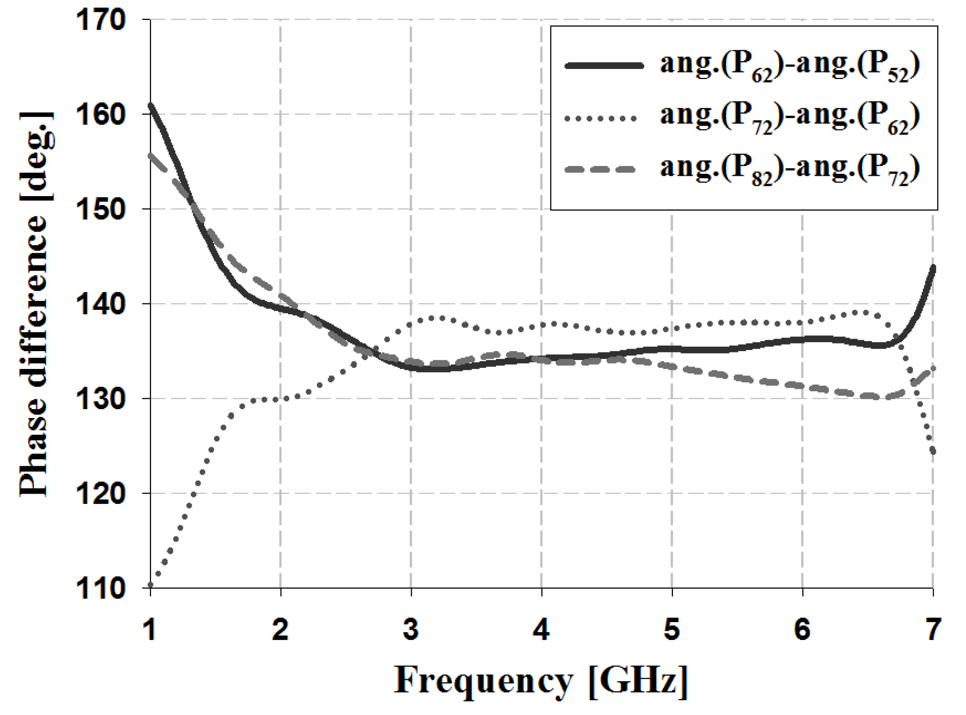
| Output Port | Phase [Deg.] | Phase Difference [Deg.] | ||||||
|---|---|---|---|---|---|---|---|---|
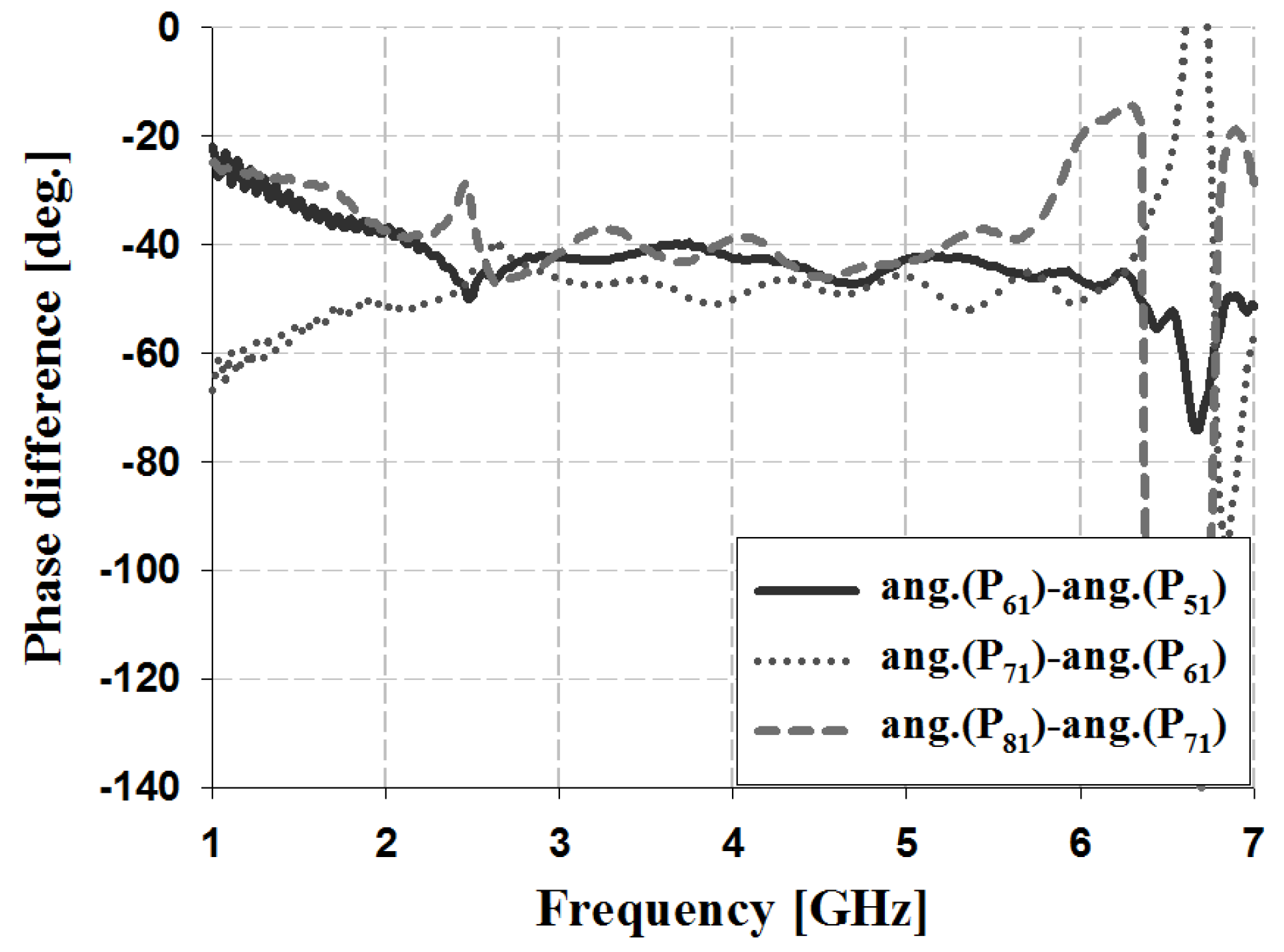
| Input Port | Port 5 | Port 6 | Port 7 | Port 8 | P5x–P6x | P6x–P7x | P7x–P8x | |
| Port 1 | 3 GHz | −68 | −25 | 20 | 62 | −43 | −45 | −42 |
| 4 GHz | 23 | 66 | 116 | 155 | −43 | −50 | −39 | |
| 5 GHz | 115 | 157 | −156 | −113 | −42 | −47 | −43 | |
| Port 2 | 3 GHz | 19 | −116 | 109 | −30 | 135 | 135 | 139 |
| 4 GHz | 115 | −25 | −156 | 58 | 140 | 131 | 146 | |
| 5 GHz | −153 | 63 | −62 | 156 | 144 | 125 | 142 | |
© 2019 by the authors. Licensee MDPI, Basel, Switzerland. This article is an open access article distributed under the terms and conditions of the Creative Commons Attribution (CC BY) license (http://creativecommons.org/licenses/by/4.0/).
Share and Cite
Kim, S.-W.; Choi, D.-Y. Analysis of Beamforming Antenna for Practical Indoor Location-Tracking Application. Sensors 2019, 19, 3040. https://doi.org/10.3390/s19143040
Kim S-W, Choi D-Y. Analysis of Beamforming Antenna for Practical Indoor Location-Tracking Application. Sensors. 2019; 19(14):3040. https://doi.org/10.3390/s19143040
Chicago/Turabian StyleKim, Sun-Woong, and Dong-You Choi. 2019. "Analysis of Beamforming Antenna for Practical Indoor Location-Tracking Application" Sensors 19, no. 14: 3040. https://doi.org/10.3390/s19143040
APA StyleKim, S.-W., & Choi, D.-Y. (2019). Analysis of Beamforming Antenna for Practical Indoor Location-Tracking Application. Sensors, 19(14), 3040. https://doi.org/10.3390/s19143040