1. Introduction
Augmented reality (AR) is in essence the art of superimposing the computer-generated graphics onto the real world, thus merging both worlds. Thus, sometimes called mixed reality (MR) or extended reality (XR) in a broader sense, AR depicts its unique characteristic compared to virtual reality (VR). In a VR setup, a user is typically completely cut off from the real world by blocking the non-screen peripheral area of a head-mounted device (HMD). In an AR environment, conversely, a user has to remain in the physical world, and virtual contents should augment, not replace, real objects. Consequently, the portion of the real world merged with the virtual world–field of view (FOV), viewing angle or interaction area in other words—heavily affects the quality of experience and sense of immersion.
Bimber and Raskar in [
1] grouped AR devices or environments into three categories by their display characteristics and locations as (1) head-mounted (head-attached), (2) mobile (hand-held) and (3) spatial AR (SAR). Recently, several HMD or mobile device (such as a smart phone)-based AR experiences have been introduced, such as Microsoft HoloLens or Apple’s ARKit. Popular as they may be, however, both types of AR devices have innate limitations of being too heavy or cumbersome for users to wear or carry all the time during long-hour usage. In addition, due to limitations in the display technology and the screen size, the effective FOV that users perceive leave room for much improvement, hindering a fully immersive AR experience.
On the other hand, SAR, which is typically implemented with projection mapping on the real world surface, demonstrates the unique characteristic that the device and display are detached from the user. This characteristic of projection-based SAR, or just projection AR, offers distinctive advantages over other types of AR. As the display device is separated from the user, a minimal or even no user instrument at all is required, allowing a more comfortable, and thus immersive and longer AR experience.
The detachment of the device also grants a much wider field of view of the user in the AR environment. A projector like any other display technologies has its own limited FOV. However, depending on the installation or configuration of the projector(s), the effective FOV that a user perceives may greatly differ. For example, a projector can be simply installed far away from the wall to increase its projection surface area. In addition, a number of projectors can be installed in combination to create unified immersive projection mapping. CAVE (Cave automatic virtual environment) itself [
2] and CAVE-like environments, such as RoomAlive [
3], are prominent examples of this immersive projection AR setups. In an CAVE-like environment, generally multiple projectors and cameras are installed around a cubic space, where four (front, right, left, floor) or more faces out of six are fully covered with projection graphics. With every surface mapped with projection images, the room itself is converted into an AR space where the effective FOV can overcome the FOV limitation of a single physical projection device.
However, if we closely examine the examples of the CAVE-like environments, other drawbacks of the AR environment setup are noticeable that could negate the initial benefits of projection AR. The foremost limitation is the excessive number of the devices needed to configure an AR space. To install a minimal form of a CAVE environment, four projectors are required to cover four surfaces of the room. In other examples such as [
4] or [
5], six projectors + eight Microsoft Kinect and five projectors + seven tracking cameras were respectively used to implement CAVE-like environments. Various restrictions sequentially stem from the large amount of hardware required for the CAVE-like environment. For instance, one just may have not enough budget to purchase all the devices. In addition, there are technical and physical challenges to install the entire system. Projectors and cameras have to be installed in a specific manner, so that they overlap and do not leave out any blind area, which all require both technical expertise and physical labor.
One solution to reduce the number of hardware required would be to utilize a steerable platform as did in Everywhere Displays [
6] or Beamatron [
7]. In both projects, a pan–tilt system was adopted to rotate the projector. The pan–tilt system allowed for augmenting rendered graphics on demand in 360° direction without using multiple projectors, which can remedy the budget limitation. If needed for the application, an RGB-D camera can be adopted to capture geometry information or track user’s interaction, comprising a projector-camera (pro-cam) unit. Then, the pro-cam unit is mounted on the steerable platform [
7].
However, exploiting the 360° rotation capability does not always guarantee an immersive AR experience. To illustrate, in [
7], the user had to stand in front of or in between the projection to interact with the system, since the only camera is rotated with the projector on the moving platform. If the user is out of the camera view, she has to manually call out command words to regain control of the system and orient it to herself. This not only limits the interaction area to the frontal area of the pro-cam system but also potentially causes blindness by the emitted projector light [
8].
In this paper, we take a hybrid approach of both CAVE-like and the steerable systems to tackle the limitations present in either methods. To keep the number of the devices to a minimum, we utilize a pan–tilt pro-cam unit for immersive projection. To cover a large portion of the interaction area as CAVE does, we adopt an external camera in addition to the steerable pro-cam system, to track and interact with the user. Named PPAP, in short for Perspective Projection Augment Platform, the proposed system fully exploits the advantage of the actuated projector, by tracking the user’s viewpoint and automatically adjusting its orientation accordingly. Consequently, the system delivers seamless 360° projection AR with wide head-coupled perspective, which we call
actuated perspective projection (
Section 3.2). Our contributions to the literature can be summarized as follows:
We propose the design and configuration of a unique projection mapping system, where a stationary camera is used jointly with a pan–tilt motorized projector-camera unit.
We describe steps to calibrate and register multiple heterogeneous devices and control methods to consequently realize actuated projection mapping with such a system.
We demonstrate how the dynamically actuated projection with widened user-perspective benefit users in terms of correctly perceiving the spatial relationship of virtual objects.
3. System Description
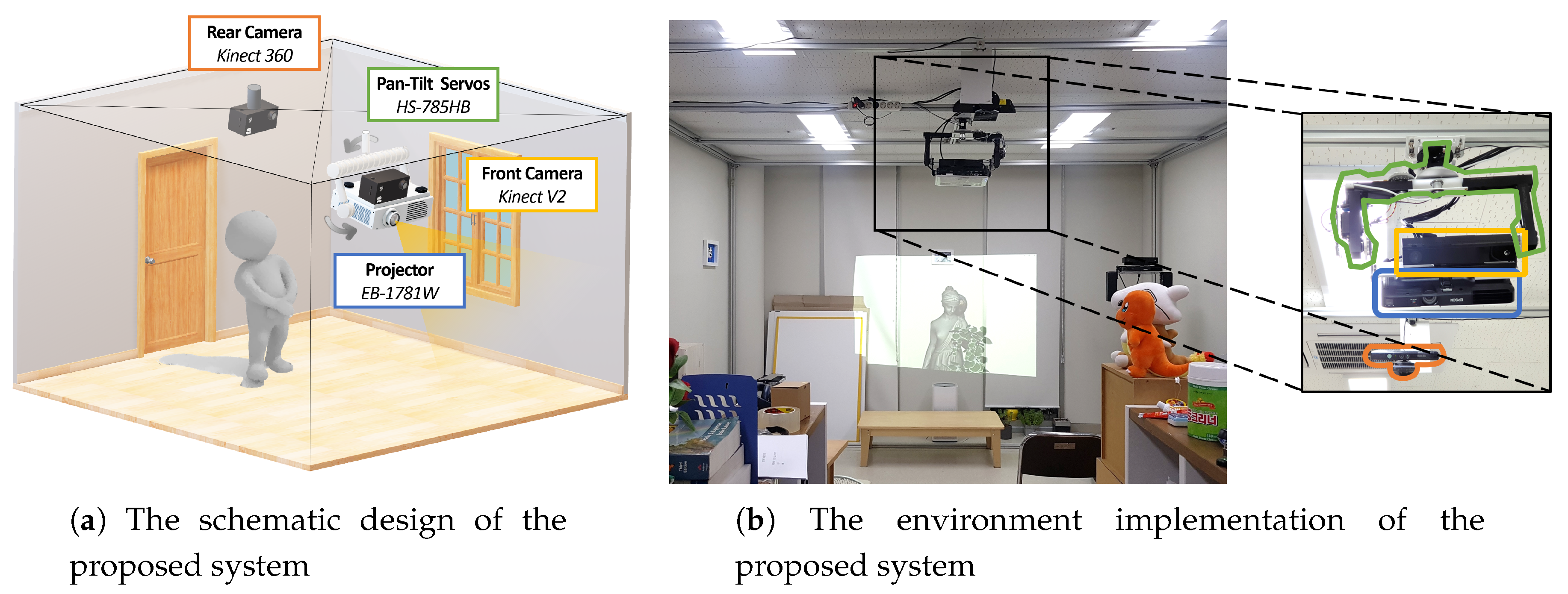
Figure 1 describes the configuration and environment setup for the proposed system. The system comprises a projector-camera unit motorized by two pan and tilt servo motors, and a rear camera, set up in a 3.7 × 4.0 × 2.25 m
(width × depth × height) cubic space. An Epson EB-1771w projector (Long Beach, CA, USA) and Microsoft Kinect V2 (Redmond, WA, USA) were assembled as a projector–camera unit and mounted on a custom-made pan–tilting platform. The platform was operated by two Hitec HS-785HB servo motors (Poway, CA, USA), which were capable of multi rotations in a standard duty cycle. Thus, 360° projection-mapping was enabled with the pan–tilt platform. Microsoft Kinect 360 was adopted for tracking and measuring a user’s position and orientation. While the pan–tilt projector-camera unit and Kinect 360 were installed on the ceiling, the former was installed in the middle of the room while the latter was installed in the rear side of the room. This positioning decision was to maintain similar projection quality in any direction or area of the room, while enabling user-tracking in a wide region with a single camera.
Both front and rear cameras, Kinect V2 and Kinect 360, provide color and depth image streams. The front camera captures the data of the surface geometry that is to be projection-mapped and the rear camera tracks the user’s position and interaction in an AR scene. The user’s viewpoint and pose combined with the geometry data are employed to ray-cast the user’s line-of-sight and determine its center on the projection surface. The system computes optimal rotation angles of pan–tilt servos to fixate the projection center to the user’s view center. Then, the front camera and projector unit on the pan–tilt platform controlled with two HS-785HB servos is steered to provide 360° projection with the correct user’s perspective. As the system consistently adjusts its attitude with regard to the user’s position and perspective, the user’s view of the virtual object can be maximized and the user can be fully immersed in the AR scene. The overall process of the proposed system to control servo rotations is described in
Section 3.2 and its effect in
Section 4.
3.1. Projector-Camera-Servo Registration
In order to seamlessly integrate the user’s perspective in both the virtual view and the real world, cameras and the projector for vision capture and projection mapping should be solidly registered in a single common coordinate system. Thus, the problem of calibrating multiple device coordinate systems in a single common coordinate system arises. The calibration process is carried out in a pairwise manner, where all the calibrations between the front camera and the projector, between the front camera and the pan–tilt platform and between the pan–tilt platform and the rear camera should be taken into account. We solve for internal and external calibration parameters with multi-camera calibration [
3] and pan–tilt rotation calibration [
16] combined.
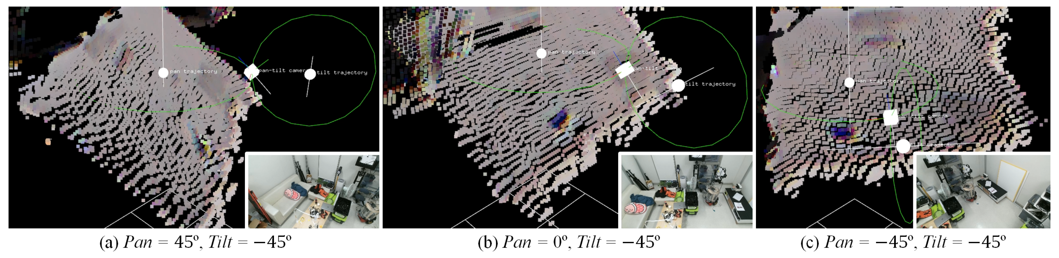
To bring all cameras and the projector to the common coordinate system, first there must be some portion of their views that are visible all among them. Therefore, the pan–tilt platform is rotated to a certain pose so that two front and rear cameras share a common view of some area of the projection. Generally, the pan servo is set to face the front and the tilt servo is set to match the pitch angle of the rear camera. In the proposed setup (
Figure 1b), the pan rotation was set to 0° to face the wall and the tilt rotation was set to 45° with regard to the floor. We define the coordinate system of the front camera at this pose as the
reference pose.
3.1.1. Projector–Camera Calibration
The
reference pose is defined to establish a common coordinate system between the front and the rear camera. Using the gray code scanning [
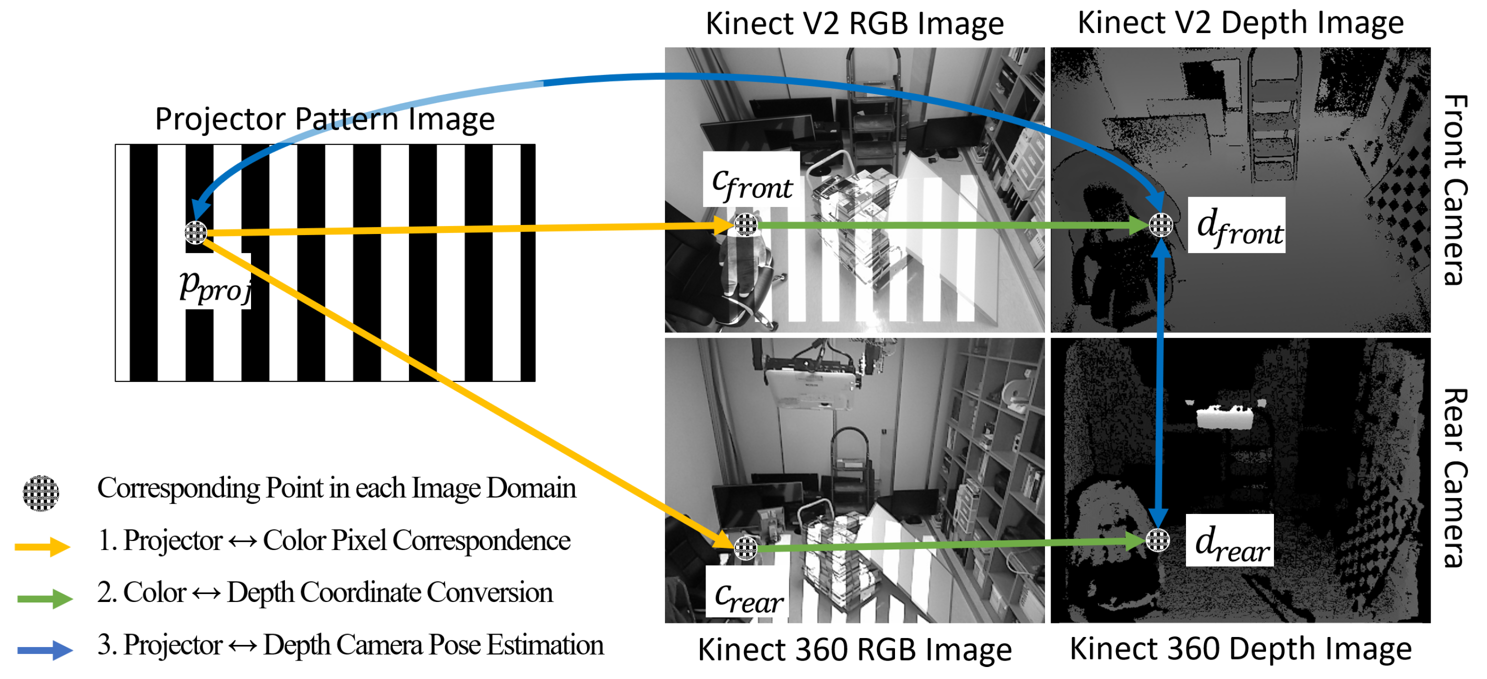
30], one can calibrate between two front and rear cameras, and between the front camera and the projector as well.
Figure 2 describes the process for the multi-camera-projector calibration. First, gray code patterns are projected, which are captured by the front and rear cameras. The pixel correspondences are computed between the projector and each color camera. The color points of the corresponding pairs are converted to depth points, which are computed with color-depth calibration data from Kinect SDKs (Software Development Kit). Then, the depth points are un-projected into the 3D space. The 3D points combined with their corresponding points in the image domains are used to calibrate cameras and the projector using Zhang’s method [
31]. We calibrate the projector as a reverse-camera model to acquire focal lengths
,
, principal points
,
and its augmented
transform matrix
, with respect the
reference pose of the front camera. The
translation and rotation matrices of the rear camera are also calibrated with respect to the
reference pose. Using the calibrated parameters, a 3D point from the rear camera’s perspective is converted to a corresponding point in the
reference coordinate as follows:
3.1.2. Camera-Servo Rotation Axis Calibration
The front camera and the projector are fixed to the pan–tilt platform. Consequently, the transformations of their poses are dependent on the rotation of the pan–tilt platform. Thus, in order to accurately estimate the poses of the front camera and the projector, one has to model the movements and trajectories of the pan–tilt servos [
16]. Following the steps described in the stated paper, a large checkerboard is placed in front against the wall. The rotation parameters of the pan–tilt platform are recovered in the
reference coordinates, based on the corner points of the checkerboard. Denoting the pan and tilt rotation angles as
and
, the rotation parameters, which are positions and orientations of the rotation axes are respectively represented as
,
,
,
. Based on the parameters, pan and tilt rotation trajectories can be modeled and the pose of the front camera on the rotation trajectories can be estimated (
Figure 3). All combined, a point captured by the front camera is represented in the
reference system as follows:
P represents a point in 3D space.
R and
t are
matrices, respectively, for rotation and translation in 3D space. For simplicity, the term
is shortened as
.
3.2. Servo Control with User Perspective
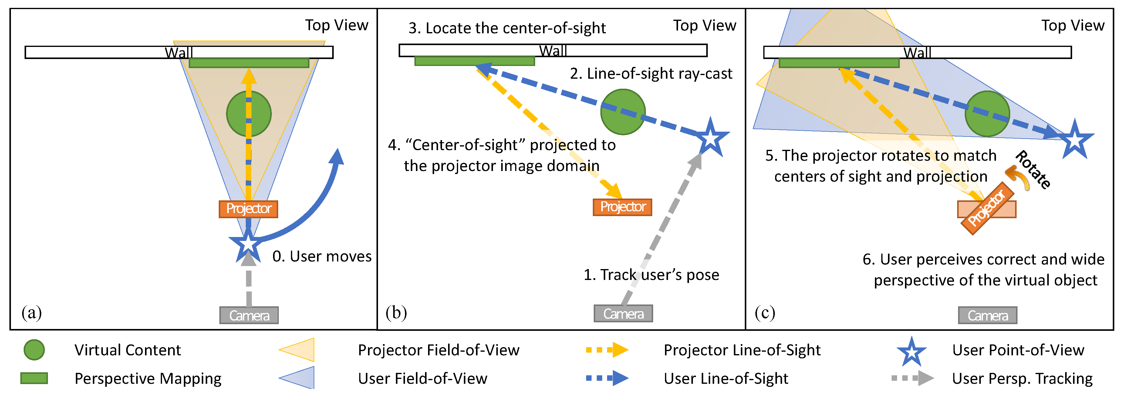
In a projection-based AR environment, the visible region of the AR scene to the user is eventually restricted, as there is a limit to the projector’s field-of-view. To overcome this limitation, the proposed system provides motorized projection mapping, which is coupled with the user’s perspective in the AR scene. The overall process is illustrated in
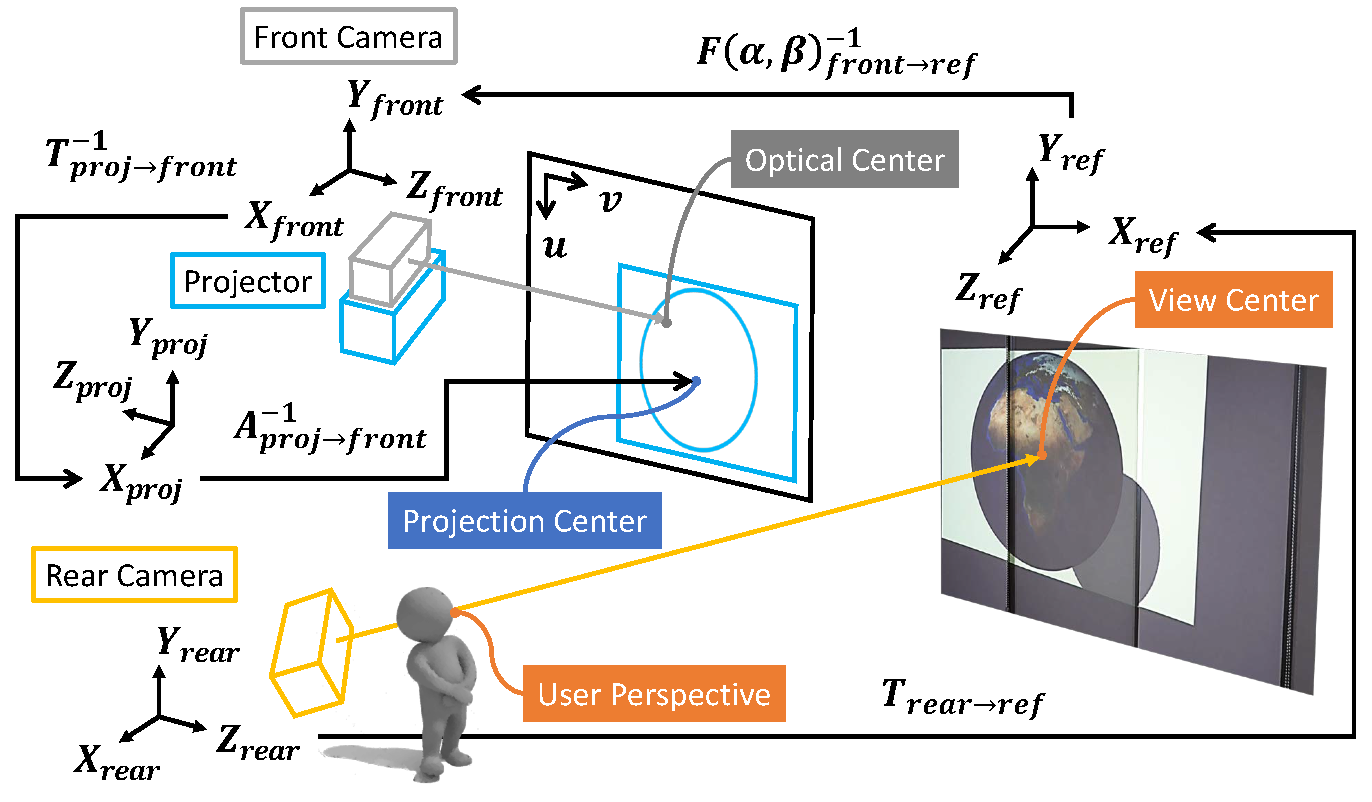
Figure 4. First, the rear camera of the system consistently tracks the user’s position and orientation and computes the user’s line-of-sight. Next, the user’s line-of-sight is ray-casted to determine the user’s view center on the object-of-interest in the AR scene. The view center is then projected on the image domain of the projector. Given the
perspective matrix
and the pose matrix
matrices of the projector, a point in 3D space is projected to a normalized 2D point on the projection image plane as follows (
Figure 5):
Here, s represents the scale factor in homogeneous coordinates. are focal lengths and are principal points of the calibrated projector. are respectively width and height pixels of the rendered projection image. All combined, they consist of the perspective matrix for the projector:
The pan–tilt platform is rotated to match the view center and the projection center, so that the user can perceive the augmented content in a more widened viewing angle. Then, the goal is to find the rotation angles
and
that minimize the following displacement error in Euclidean distance:
Points are calculated on the normalized image domain. Thus, the image center is at the origin,
. Thus, we directly minimize the squared distance of the projected user’s view center from the origin. We solve this optimization problem based on the inverse kinematics approach, by extending the method of [
16] for controlling servo motors to work with the projection point.
Since
,
and
are all parameters with calibrated or given values, we can adopt the inverse kinematics algorithm in [
16] by simply modifying the error and parameter vectors as
and
, respectively. By computing Jacobian matrix
of Equation (
3) of the current pose, we can iteratively solve for two arguments
,
of
.
3.3. Actuated Projection with Perspective Mapping
In the proposed system, the geometry information of the projection surface is acquired by the front camera and the user’s viewpoint and orientation are acquired by the rear camera. Microsoft Kinect V2 SDK’s skeleton tracking and PoseNet human pose estimation [
32] were combined to respectively acquire the head position and eye positions. Then, the orientation vector is computed with triangulation of the three points. The user’s line-of-sight ray is casted from the head position, following the orientation vector’s direction. If eye positions are not available, the ear positions are used instead to determine the head orientation.
The user’s viewpoint and orientation are converted to
reference points using Equations (
2) and (
1). The user’s perspective is then ray-casted to the surface geometry to compute the center of projection. The inverse kinematics algorithm [
16] with the center point of Equation (
3) determines the pan–tilt rotation angles
and
. With user’s perspective projection matrix
formed as [
33], Algorithm 1 is established to realize actuated perspective projection.
| Algorithm 1 Actuated Perspective Projection |
for each frame do Receive 3D points and the user’s viewpoint Compute pan–tilt angles and with Equation ( 3) Configure and with Equations ( 2) and ( 1) Configure the perspective matrix from Render the view from [ 33] as texture projTex Set rendered result as projTex for projective texture for each in do Compute texture coordinate projCoord Map projTex onto with projCoord
|
4. User Experiments
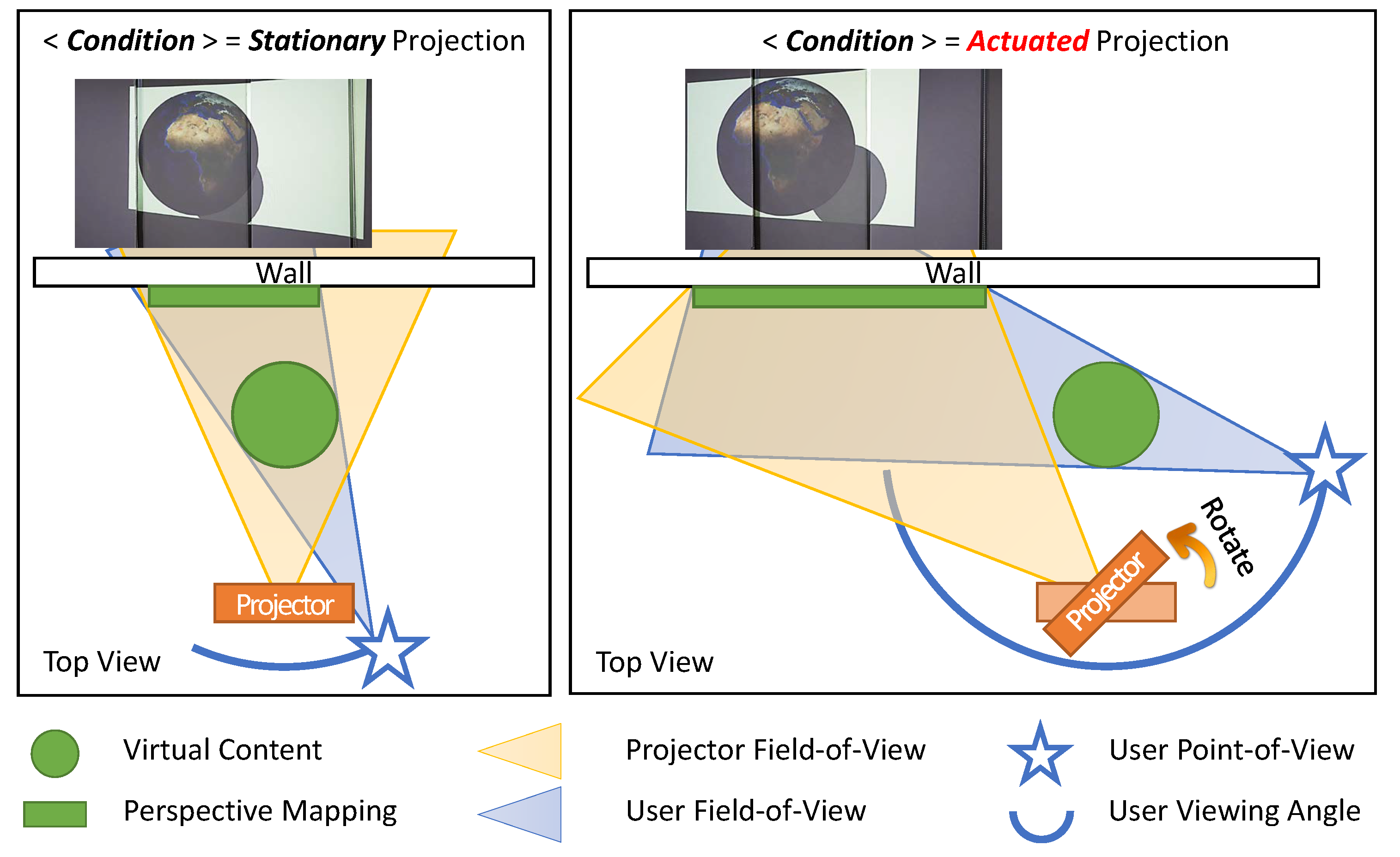
As illustrated in
Figure 6, the
actuated perspective projection enabled by the proposed system provides the user with a much wider view in the projected augmented environment, when compared to the
stationary projection environment such as [
27]. Note that the
stationary projection does not mean that the projection itself is static. It is the projector that is stationary, and the rendering is still coupled to the user’s head. To evaluate the effectiveness and usefulness of the proposed
PPAP system, we conducted a user experiment that can demonstrate its characteristic, which is the widened viewing angle in a projection AR scene.
In monoscopic projection AR, the augmented virtual scene is mapped onto the real world surface, without the stereopsis effect that boosts the spatial perception. In such cases, various spatial cues can aid subjects with perceiving spatial relationships in an AR scene, including perspective projection, shading, shadow mapping and motion parallax [
24,
26]. In the experiment, we focused on examining the effectiveness of increased motion parallax on a user’s sense of the virtual object’s spatial presence in the monoscopic perspective projection AR environment. Specifically, we examined whether users can perceive spatial relationships of the projected object as spatial in mid-air, rather than as merely projected on the surface, and which factors affected their perception.
We recruited 11 participants aged from 25 to 31 (mean = 27.1 years, standard deviation = 1.8 years). All participants completed the experiment and were asked to give their subjective opinions on their experience with the proposed system and the experiment. The total session including the experiment and the interview took approximately 30 min to complete.
4.1. Experiment Design
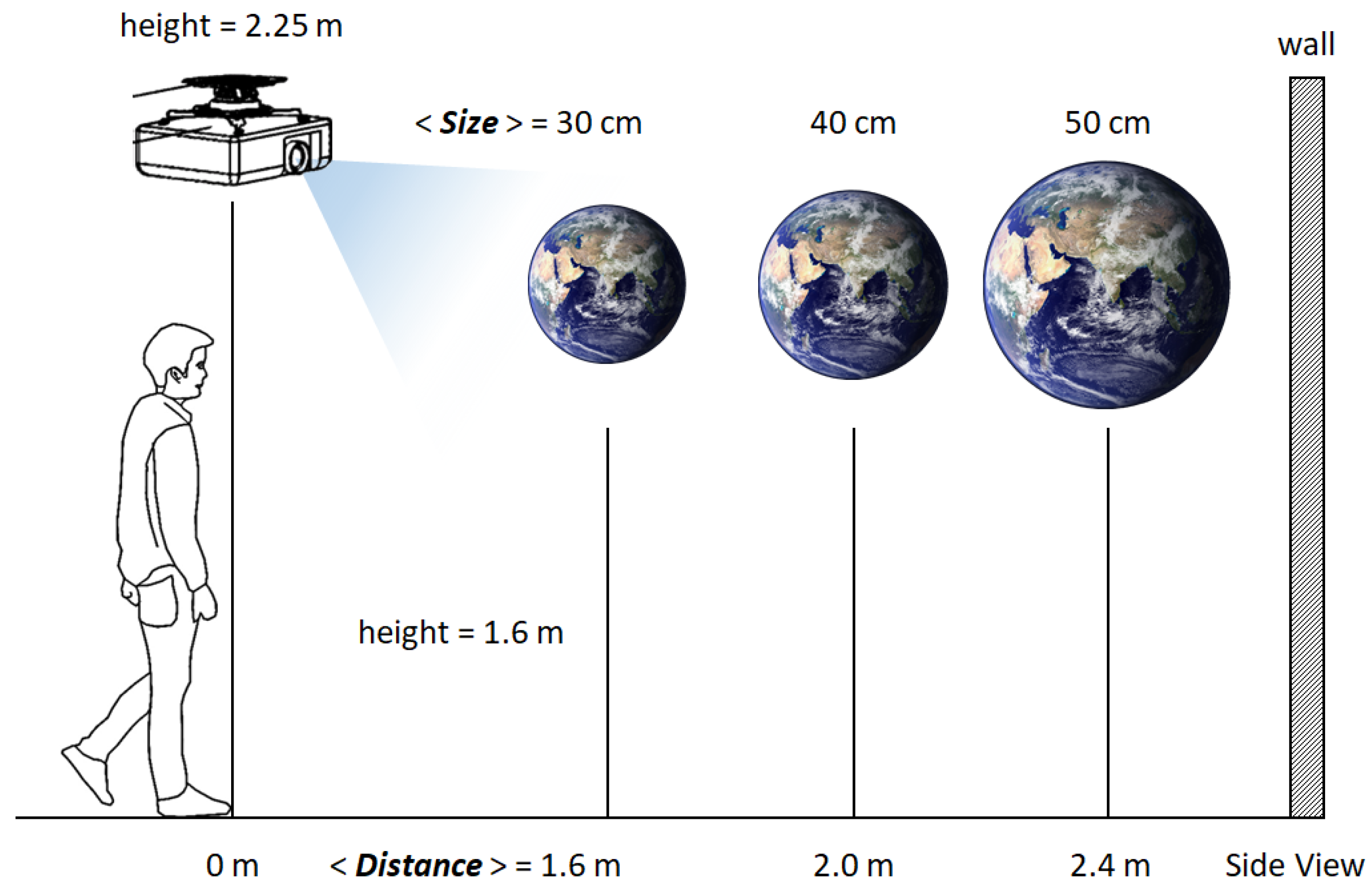
To measure how users perceive the spatial presence of a virtual object, the participants were asked to rate the size and distance of the virtual objects, similar to the experiment design of [
27]. As illustrated in
Figure 7, a globe was chosen as the test object and was projected with three different sizes (30 cm, 40 cm and 50 cm radii) and three different distances (1.6 m, 2.0 m and 2.4 m away) virtually hovering at 1.6 m height. The back wall on which virtual objects were projected was approximately 2.8 m away from the origin. The sizes and distances were designed so that the objects with different size*distance configurations may be perceived as roughly the same by the users. For example, the largest yet farthest object and the smallest yet closest object appear as if they are of roughly the same scale. These confusions were intentionally designed to minimize obvious answers and robustly evaluate the effect of the experiment conditions on user’s spatial perception. We imposed much harsh conditions (less discernable size*distance configurations) than those of [
27] to better manifest factors that influence correct spatial perception.
The main purpose of the experiment was to analyze the effect of the
actuated perspective projection, where the projector unit rotates itself to match the user’s view center and the projection center so that users can view larger parts of the virtual object before it goes out of the projection range. Thus, in addition to different size*distance combinations, the experiment was conducted with two different conditions, namely
stationary and
actuated (
Figure 6). In the
stationary condition, the pan–tilt head remained stationary throughout the experiment. In the
actuated condition, which is the proposed system, the pan–tilt head continuously steered to match the centers of the user’s view and the projection.
In [
27], two different conditions “with physical markers” and “without physical markers” were used to evaluate the effectiveness of the projected SAR system proposed in the stated paper. In this paper, no physical markers were used throughout the experiment. The rationale behind this decision was two-fold. First, we assumed that users could perceive spatial relationship in an AR scene without the aid of physical markers, as no statistical importance was found between “with” and “without” conditions in [
27]. Second, we wanted to observe the sole influence of the projection condition, which is whether the projection is
stationary or
actuated, on the user’s spatial perception performance. Without any other affecting factors, the effect of the proposed system could be well manifested.
Through this experiment, we aimed to verify the following hypotheses:
H1. The participants are able to perceive spatial representation of the virtual objects, which are projection-augmented.
H2. The participants are able to rate the size and distance more correctly if they can view wider range of the augmented object.
H3. The actuation of projection can enhance the depth perception, which is attenuated as the projection surface is distanced.
To summarize, the experiment was designed to have 18 configurations (Size (3) × Distance (3) × Condition (2)). For each participant, three trials of the 18 configurations were performed, which yielded total 54 ratings. We note that the experiment was designed as within-subjects. Thus, participants were randomly partitioned into two half groups and the presentation order of stationary and actuated conditions were counterbalanced between groups.
4.2. Experiment Procedure
Before the experiment began, the participants were briefed about the experiment including the system description, experiment goals, their rights, limitations and so on. The descriptions were given both verbally and in literal forms on their information sheets.
The participants were then asked to stand at the origin point, which we defined as the perpendicular foot of the projector-camera unit to the floor. They were given a session to familiarize with the system and practice before the actual experiment began. In the practice session, nine size*distance configurations of the earth globe projection with correct answers were presented to the participant, in the stationary projection condition. The rationale behind this decision was that the proposed actuated projection was a superset of the stationary projection and the test group. Thus, it would be only fair for users to familiarize with the system in the stationary projection condition. No time limit was imposed on the practice sessions, yet all practice sessions took less than two minutes to complete.
As noted earlier, the presentation order of stationary and actuated conditions was counterbalanced between two half groups, in order to minimize the learning effects caused due to the ordering. For both groups, participants carried out two conditions in a sequence. Between conditions, participants were given a short break while the coordinator gathered the results. For each condition, the presentation orders of the projection conditions were randomized beforehand, and fixed throughout the experiment for all participants.
In the experiment, the participants rated the size and distance of the the projected virtual earth globe verbally, using terms “small”, “medium” and “large” for the size and “near”, “middle” and “far” for the distance. For each size*distance configuration, a 15-second time limit was imposed on the participants. The time limit was relatively loose when compared to that of [
27] (5 s). This design decision was made to reflect the characteristic of the proposed system, where the effective FOV of the projection could be enlarged by orienting the projector in accordance with the participants’ viewpoint (
Figure 6). Thus, the participants were given ample amount of time to, and were encouraged to, actively move around and investigate various regions of the virtual earth globe.
The participants were directed to give their ratings when they felt confident. They were waited until the allotted time expired. Then, the projection was turned off (rendered black) and participants were urged to report their ratings as quickly as possible. The reported ratings were recorded by the coordinator. Then, the trial with the next configuration was carried out. The time for participants to make their decisions was not measured, as we rationalized that the 15-second time limit was generous enough for participants to make thorough decisions and thus their response time held low significance.
4.3. Results and Analysis
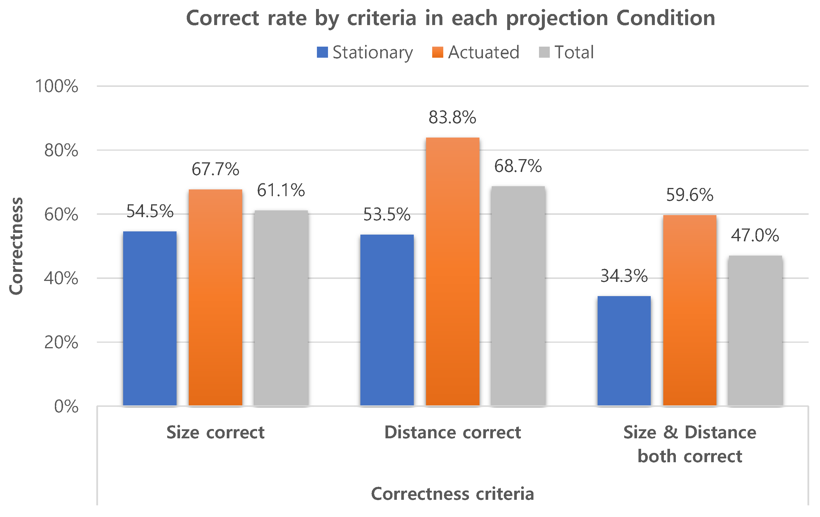
4.3.1. Hypotheses H1 and H2
Figure 8 summarizes the experiment results on how users accurately perceived the sizes and distances of the virtual object. For the hypothesis H1, we only investigate the total results in the graph. The participants were able to correctly rate 61.1% of the size variations and 68.7%of the distance variations. If we assess the overall correctness, that is, when both the size and distance are correct, the participants were able to correctly rate 47.0% of all size*distance combinations. Since there were nine size*distance combinations of the virtual object, a random guess would have 11.1% (1 out of 9) chance of being correct. The overall correct rate of 47.0% is significantly higher than the random guess probability 11.1%. These results confirm our first hypothesis H1 that participants can correctly perceive the presented spatial relationship of the virtual objects, which are projection-augmented by the proposed system.
We constructed confusion matrices, predictions vs. ground truth, from the participants’ ratings of size and distance. We found that only 4.7% of the total ratings missed by more than one option, such as mistaking a “near” distance as “far”. The low percentage of missed-by-more-than-one-option answers is important in two things. First, it is another piece of evidence for hypothesis H1 in which participants are able to perceive virtual objects’ presence correctly, at least indirectly. Second, it lays the groundwork for encoding participants’ responses into a binary scale, either “correct” or “incorrect”. The binarization of responses allows us to analyze the performance results using binomial regression, which simplifies the interpretation and analysis of H2 and H3. Since the experiment was designed as a within-subject study and categorical responses were collected, the repeated measures logistic regression should be employed [
27]. We used Generalized Estimating Equations (GEE) of IBM SPSS Statistics v25 (Armonk, NY, USA) to analyze for correctness of user’s ratings. The correlation between the experiment configuration parameters—size, distance and projection condition—and the binary correctness variable were computed. Wald Chi-Square (
) was calculated to evaluate the statistical significance of each predictor to the model.
Three variables, Size, Distance and Condition, were chosen as predictors to analyze the overall correctness and tested for correlations on the model. We set significance level as = 0.05, Thus, we found something statistically significant and rejected the null hypothesis, if the associated p-value was p ≤ 0.05. The condition, whether the projection was stationary or actuated, was found to have the statistically high significance ( = 12.431, df = 1, p < 0.001), while the size ( = 2.139, df = 2, p = 0.343) and distance ( = 5.201, df = 2, p = 0.074) were found otherwise.
Figure 8 summarizes correct rates in each projection condition. The overall correctness results grouped by condition were 34.3% with the
stationary projection, and 59.6% with the
actuated projection. The statistical significance of the projection condition, and the difference in the overall correctness between projection conditions firmly support hypothesis H2, that the participants are able to rate the size and distance more correctly when the viewing angle of the augmented object is wider. These results also support hypothesis H1. Since different results were produced when the projection condition was changed, it would be rational to conclude that the participants’ answers were neither random, nor memorized from their training sessions, but the results of spatial perception.
During the subjective feedback session, participants reported that they were more comfortable and immersed in the actuated perspective projection condition, and thus it was more easy to notice the spatial relationship of virtual object, which coincides with the quantitative assessment. We conjecture that the actuated perspective projection widened the viewing angle, and consequently results in greater motion parallaxes and more shadow mapping effects. Combined with the statistical analysis results, we conclude that the proposed system (actuated projection) improved the spatial perception and presence of the projection mapped AR contents.
4.3.2. Hypothesis H3
Previously, several research papers on projection AR have reported that the projection quality degrades as the projection surface is distant, and users find augmented objects less present as a result [
27,
34]. Hypothesis H3 was designed to test whether the proposed
actuated perspective projection can mitigate the effect of the projection quality degradation, and enhance virtual objects’ spatial presence. Thus, we analyzed subsets of result data and investigated in detail how the projection condition affected users’ depth perception by the distance.
Statistical analysis showed that the Distance factor was significant with both the
stationary projection (
= 9.695, df = 2, p = 0.008) and the
actuated projection (
= 5.992, df = 2, p = 0.049). However, distributions of two subset results were found to be quite different from each other, as shown in
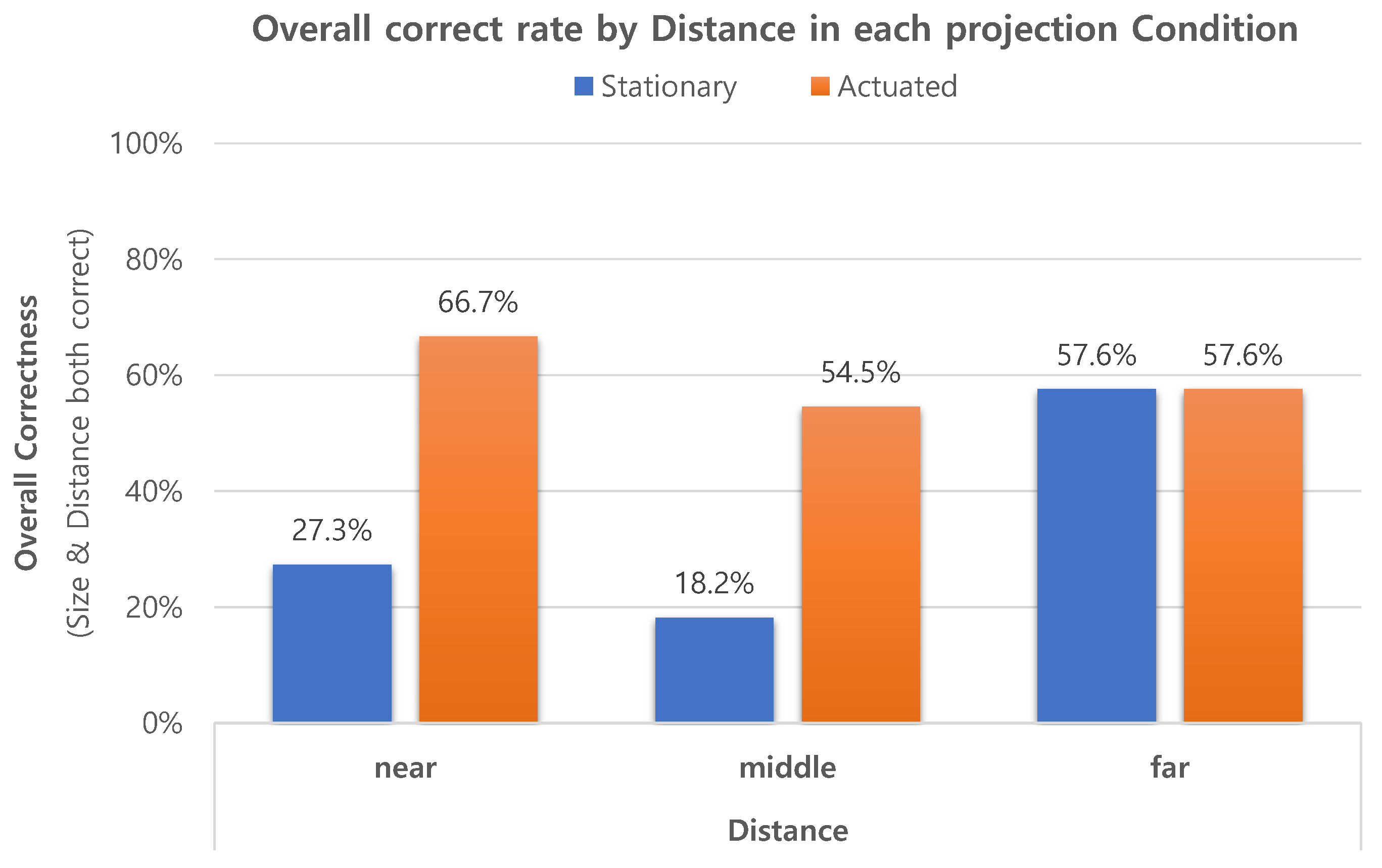
Figure 9. In the
stationary condition, the correct rates were 27.3%, 18.2% and 57.6%, respectively, for “near”, “middle” and “far”, the experiment configuration and result distribution of which are similar to [
27]. On the contrary, in the
actuated condition, the correct rates were 66.7%, 54.5% and 57.6%, respectively, for “near”, “middle” and “far” in the
actuated condition, showing the opposite distribution, where the better performance was achieved as the distance was closer.
The discrepancies in correct rates between stationary and actuated conditions indicate clear improvements of the participants’ spatial perception in “near” and “middle” distances, while they performed the same in the far distance. We conjecture that the actuated projection mapping of the proposed system negated the degradation of the virtual presence in projection AR, and boosted the participants’ spatial perception, even if the virtual object was far detached from the projection surface.
The accompanying rationale is illustrated in
Figure 10. In the
stationary projection, the visible angle of the virtual object becomes greatly limited as it is located closer to the user. This is because the projector’s FOV is fixed, and thus the visible area of the virtual object is limited depending on the projection distance. On the contrary, in the
actuated projection, the projector can be rotated, which increases the effective FOV of the projection. Thus, regardless of the virtual object’s position, provided that the user’s perspective view of the object is within the bound of pan–tilt servo rotations, the projector can augment the object with correct spatial presence and perspective.
4.4. Discussion and Limitations
Monoscopic projection is well known for its wider viewing angle and for its freeing users from the instrumentation, which are two major limitations in other types of AR, especially in the case of mobile AR and HMD. However, it is also reported that the projection of the virtual content that was far from the surface degraded in quality [
34], and it resulted in users’ under-performance in perceiving spatial presence of virtual objects as they were distanced from the surface [
27].
We believe that the proposed system can boost the strength and mitigate the weakness of the monoscopic projection AR, since all three hypotheses of the actuated projection are validated through user experiments. The actuated projection increases the viewing angle in an AR scene over the physically limited field-of-view of the projector, to the scope of 360° by steering and coinciding the display region of interest with that of the user. Moreover, the actuated projection not only delivers the spatial presence of virtual objects in ideal conditions, i.e., the projection is close to the surface, but also preserves it comparably in harsh conditions where the projection is distanced from the surface. Since improved spatial perception leads to enhanced spatial presence, we believe that the proposed system can ultimately promote immersion in an AR environment.
While all is promising, there is still room for improvement in the proposed method. As the proposed actuated projection anchors to a specific user’s viewpoint, it may not be ideal for hosting multiple users in a shared virtual environment. In such a scenario, we believe a couple of strategies from the literature can be applied to support multiple users and provide good perspective in the shared AR environment.
Firstly, the “master” user strategy of [
5] could be adopted in the proposed system. The paper introduced the concept of the “master” user for projection mapping in a CAVE-like environment. In the environment, dinosaur-related contents such as anatomy and habitat were presented to users, via projection mapping. As virtual contents were projection-mapped onto a real physical model of a dinosaur, self-shadowing was inevitable. To reduce visible shadows, the position of the “master”, chosen among viewers, was correlated with the projectors’ frustums. Other users were were guided to an
ideal viewpoint with good perspective positions, using color-coded circles with an additional arrow. Since the
actuated projection is optimized for a single user’s perspective, the “master” user strategy can be directly applied to the proposed method for multi-user scenarios.
Secondly, the Dynamic Zoning approach proposed in [
35] could be adopted in the proposed system. The Dynamic Zoning approach tackles the problem of rendering multiple users’ views in a surrounding virtual environment. Particularly, in a specific case when two users are looking in the same direction, the scene is rendered from the “democratized” point between users’ head positions. If applied to the proposed system, the wide-area camera can track multiple users’ viewpoints, and average the viewpoints. Rendered from midpoint, the equal experiences can be provided to all users.
4.5. Possible Application
The proposed system is capable of tracking a user’s viewpoint, and dynamically augmenting virtual objects with actuated projection. Thus, the proposed system has the advantages in projection AR environments, where a solo or key user is allocated with a focused view of the AR scene. In such environments, the proposed system may be adopted to replace the existing hardware, or to extend the function of the current installation. We believe the characteristic of the proposed system raises many potential possibilities and applications for the projection mapping.
For example, Gallery Invasion [
36], which was a projection-based art installation in an art gallery, was implemented with a projector with a moving mirror to provide three-sided wall projection mapping. Although the projection was immersive and magical, the viewpoint in the rendered graphics remained fixed throughout the play, limiting the chance of participatory experiences. This is because there was no equipment for user tracking, and the system had to assume that the user always stands at a predesignated point.
The used hardware is similar to the proposed system in that they all support 360° projection mapping. However, the proposed system is also capable of capturing 360° geometry information and tracking users’ positions and perspectives in a wide area. Thus, if the proposed system had been adopted instead, we believe the viewer could have experienced the projected contents in full, as they were able to move and engage freely in the AR environment.

