Towards an Efficient Identification Process for Large-Scale RFID Systems †


Abstract
1. Introduction
2. Related Work
2.1. Multi-Reader Scheme: MR-Scheme
- Reader-to-reader collisions. This problem, also known as frequency interference, occurs whenever a reader tries to catch a signal from a tag and is masked by the signal from a nearby reader.
- Reader-to-tag collisions. This problem occurs when two or more readers try to simultaneously access a tag. This phenomenon may occur when the tag is in the coverage area of more than one reader, i.e., within an overlapping area.
- Anti-collision algorithms based on coverage. These types of algorithms aim to minimize the overlapping areas between the readers. To do this, each reader adjusts its transmit power in order to adapt its communication range. A central node is needed to coordinate the whole set of readers.
- Anti-collision algorithms based on resource allocation. They reserve and allocate the resources available to a reader, e.g., frequency, time, bandwidth. Resource allocation is made according to the application requirements or as fair as possible.
- Anti-collision algorithms based on control mechanisms. These algorithms use control packets to indicate that a reader is communicating with a set of tags.
2.2. Distributed RFID Sensing
- Illuminator. This device is very similar to an RFID reader. An Illuminator does not receive responses from the tags, it just energizes them and sends queries. The Illuminator is envisioned to account with more transmission power than an RFID reader, and therefore, a larger coverage range.
- Listener. The main function of this new device is to collect responses from the tags. In order to do so, firstly the RFID listener needs to decode the Illuminator’s commands. To collect the tags’ responses, an RFID listener may use cooperative reception techniques as is discussed in [8]. These kinds of techniques enable the RFID listener to retrieve useful information from a collision. Thus, the RFID listener acts as an intermediary between the Illuminator and tags since it can decode signals coming from both of them and is able to relay information from the tags to the Illuminator. This last feature makes the RFID listener a very helpful device during the deployment of an RFID network.
- Tags. These are devices with a unique ID, they are attached to the objects to be identified. They are very limited on storage, communication, and processing power.
Cooperative Reception Techniques
- Collision recovery. These mechanisms take advantage of collisions by seeing such phenomenon as an advantage. Surprisingly, RFID tag collisions are destructive and useless [12]. In the literature, there is work focused on multipacket reception for RFID systems [13]; however, most of such contributions suppose important modifications to the RFID devices in the network, and these modifications need to be implemented on the reader [14].
- Interference cancellation. Mechanisms for interference cancellation provide the reader with the ability to suppress the known signals from a colliding one [15], allowing the correct decoding of more than one signal. On one hand, such a function assumes additional features on the reader, e.g., extra memory to store the obtained results from previous queries, while on the other hand it increases the reading rate at an additional cost on processing time [16]. There exist several interference cancellation techniques such as the capture effect [17] that allows identification of an RFID tag even during a collision. Another example is successive interference cancellation [18] that allows identification of an RFID tag by storing a colliding signal and subtracting from it a known one.
2.3. Discussion
3. Towards an Extended Distributed RFID Sensing Protocol
3.1. System Model
3.2. Anti-Collision Protocols for Distributed Sensing
3.2.1. The EPC Class 1 Generation 2 Protocol
- No response. There is no response to the current query, which means that no tag selected the current slot in the frame.
- Unique response. Only one tag selects the current slot, allowing a correct decoding of the RN16 packet in the reader. When this happens, the reader sends an ACK packet to indicate to the corresponding tag that it has been identified. In turn, the tag responds to the reader with its ID, which completes the identification of such tag.
- Collision. If more than one tag responds in the current slot, a collision will be produced. In this case, the reader is not able to decode the RN16 packet sent by the tags.
3.2.2. The EPCGen2-LS Protocol
| Algorithm 1 Pseudo-code of the EPC Gen2 protocol for large scale RFID systems [9]. | ||
| Illuminator procedure | ||
| 1: | ← Initial Q value | |
| 2: | ||
| 3: | ||
| 4: | while (∃ Tag to be identified) do | |
| 5: | ← Estimated number of tags in listener k | |
| 6: | ← Q value for the k-th listener | |
| 7: | ← Number of empty slots for listener k | |
| 8: | ← Number of single slots for listener k | |
| 9: | ← Number of collision slots for listener k | |
| 10: | ← Frame length | |
| 11: | for to L do | |
| 12: | for all RFID listeners do | |
| 13: | ||
| 14: | if () then | |
| 15: | if () then | |
| 16: | ||
| 17: | else | |
| 18: | ||
| 19: | else | |
| 20: | ||
| 21: | ||
| 22: | ||
| 23: | ||
| 24: | for all RFID listeners do | |
| 25: | ← Estimation function [28] | |
| 26: | ← Select the optimal value of Q [29] | |
| 27: | ||
| 28: | ||
| Listener procedure | ||
| 29: | while () do | |
| 30: | ||
| 31: | if then | |
| 32: | ||
| 33: | if () then | |
| 34: | if () then | |
| 35: | ← Collision event | |
| 36: | if (Can be recovered?) then | |
| 37: | for all identifications do | ← Could be one or two identifications |
| 38: | ← The RN16 is reported to the transmitter | |
| 39: | ||
| 40: | if () then | |
| 41: | ← Wait for an ID from a tag | |
| 42: | ← The ID is reported to the transmitter | |
| 43: | else | ← Identification case |
| 44: | ||
| 45: | ||
| 46: | if () then | |
| 47: | ||
| 48: | ||
| 49: | else | |
| 50: | ← No response case | |
| Tag procedure | ||
| 51: | Detected = false | |
| 52: | while not Detected do | |
| 53: | Receive(Message); | |
| 54: | if (Message == Query|QueryAdj) then | |
| 55: | f = 2Q − 1 | |
| 56: | k = U(0, f) | |
| 57: | else if (Message == QueryRep) then | |
| 58: | k = k − 1 | |
| 59: | else if (Message = ACK) then | |
| 60: | Send(ID) | |
| 61: | Detected = true | |
| 62: | if (k == 0) then | |
| 63: | Send(RN16); | |
4. Evaluation
4.1. System Model
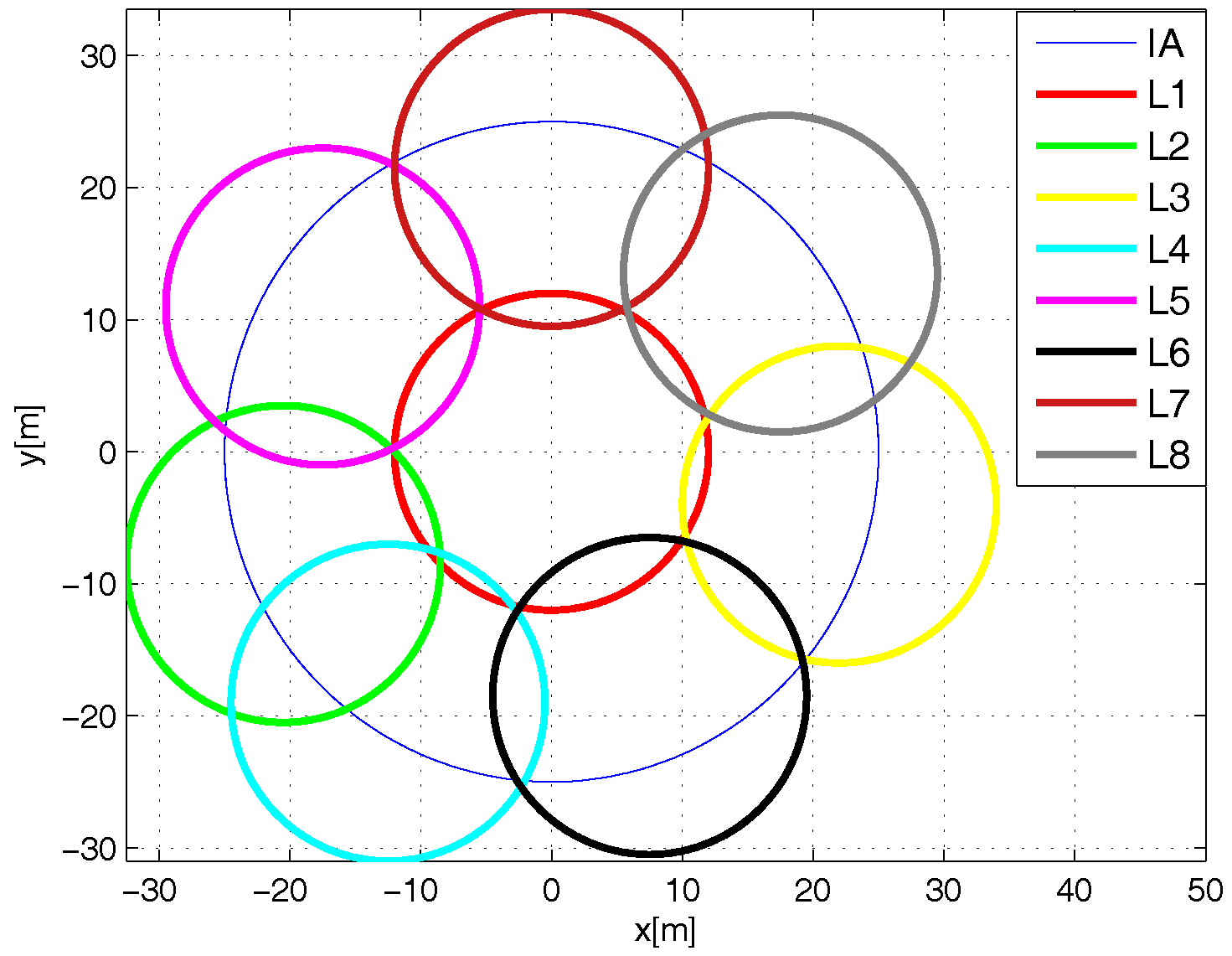
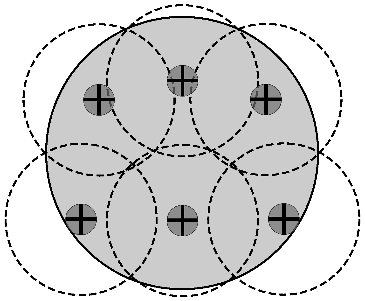
Network Deployment
- Best. For the L-Scheme, the number of tags in the sensing range of an RFID listener is the same for each of these devices. Regarding the Multi-Reader scheme, the best case occurs when the number of tags in the coverage range of an RFID reader is the same for each RFID reader. Additionally, there are no tags in the overlapping areas. This case eliminates the reader-to-tag collision events that occur with the MR-Scheme, which is not very representative of an RFID application.
- Worst. The whole set of tags is in the sensing range of an RFID listener for the L-Scheme or it is in the coverage range of only one RFID reader for the MR-Scheme. On one hand, this case vanishes the multi-reader concept. On the other hand, this case does not make any sense for a comparison between distributed identification schemes.
- Average. For the L-Scheme, the number of tags in the sensing range of an RFID listener is proportional to its coverage area. For the MR-Scheme, the number of tags in the coverage area of an RFID reader is proportional to its coverage area. In this case, there are overlapping areas and tags in such areas. On one hand, this produces reader-to-reader collisions and reader-to-tag collisions on the MR-Scheme. On the other hand, this allows the exploitation of cooperative reception techniques from the L-Scheme. Thus, this is the general case regarding the number of tags per coverage area and, therefore, the most interesting case to evaluate.
4.2. Anti-Collision Protocols and Simulation Parameters
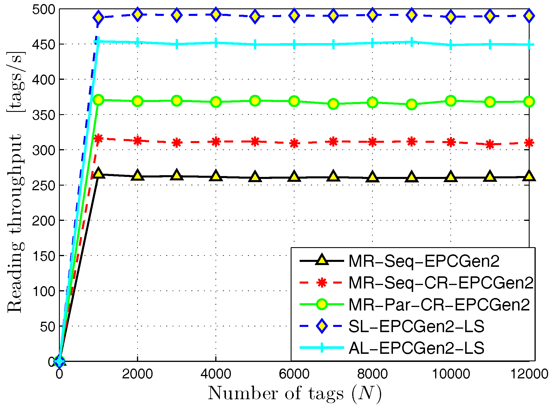
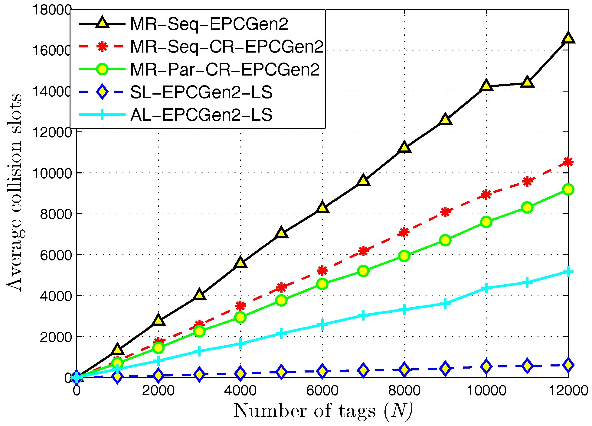
5. Numerical Results
5.1. MR-Scheme vs. L-Scheme and AL-Scheme
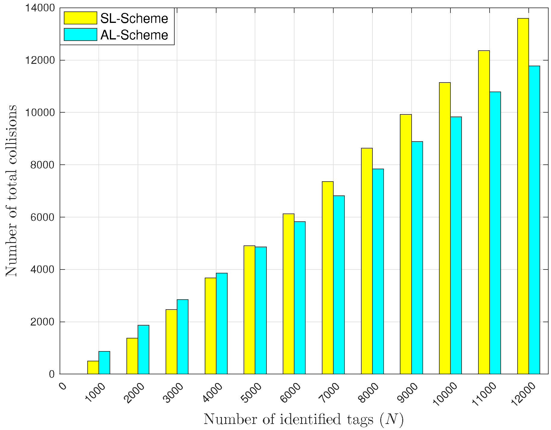
5.2. L-Scheme and AL-Scheme
6. Conclusions
Author Contributions
Funding
Conflicts of Interest
References
- Das, R. RFID Forecasts, Players and Opportunities 2017–2027. The Complete Analysis of the Global RFID Industry. Available online: https://www.idtechex.com/research/reports/rfid-forecasts-players-and-opportunities-2017-2027-000546.asp (accessed on 20 June 2018).
- De Donno, D.; Ricciato, F.; Catarinucci, L.; Tarricone, L. Design and applications of a software-defined listener for UHF RFID systems. In Proceedings of the IEEE International Microwave Symposium Digest (MTT), Baltimore, MD, USA, 5–10 June 2011. [Google Scholar] [CrossRef]
- Ali, K.; Hassanein, H.; Taha, A.E.M. RFID Anti-collision Protocol for Dense Passive Tag Environments. In Proceedings of the IEEE Local Computer Networks (LCN), Dublin, Ireland, 15–18 October 2007; pp. 819–824. [Google Scholar] [CrossRef]
- Alsalih, W.; Ali, K.; Hassanein, H. Optimal distance-based clustering for tag anti-collision in RFID systems. In Proceedings of the IEEE Local Computer Networks (LCN), Montreal, QC, Canada, 14–17 October 2008; pp. 266–273. [Google Scholar] [CrossRef]
- Tseng, D.F.; Lin, Z.C. An Anti-Collision Algorithm in RFID Systems Based on Interference Cancellation and Tag Set Partitioning. In Proceedings of the IEEE Vehicular Technology Conference (VTC-Spring), Singapore, 11–14 May 2008; pp. 1609–1614. [Google Scholar] [CrossRef]
- Ali, K.; Hassanein, H. Distributed receiving in RFID systems. In Proceedings of the 34th IEEE Conference on Local Computer Networks (LCN), Zurich, Switzerland, 20–23 October 2009; pp. 69–76. [Google Scholar] [CrossRef]
- Sanchez, L.; Ramos, V. Efficient distributed identification for RFID systems. Wirel. Personal Commun. 2017, 94, 1751–1775. [Google Scholar] [CrossRef]
- De-Donno, D.; Ricciato, F.; Catarinucci, L.; Coluccia, A.; Tarricone, L. Challenge: Towards distributed RFID sensing with software-defined radio. In Proceedings of the 16th ACM Annual International Conference on Mobile Computing and Networking (MobiCom), Chicago, IL, USA, 20–24 September 2010; pp. 97–104. [Google Scholar] [CrossRef]
- Sanchez, L.; Ramos, V. An EPC Class-1 Generation-2 anti-collision protocol for RFID tag identification in augmented systems. In Proceedings of the International EURASIP Workshop on RFID Technology (EURFID), Rosenheim, Germany, 22–23 October 2015; pp. 36–43. [Google Scholar] [CrossRef]
- Li, Z.; He, C.; Tan, H.Z. Survey of the advances in reader anti-collision algorithms for RFID systems. In Proceedings of the 50th IEEE Conference on Control and Decision (CCDC), Orlando, FL, USA, 12–15 December 2011; pp. 3771–3776. [Google Scholar] [CrossRef]
- EPCGlobal. EN 302 208-1: Electromagnetic Compatibility and Radio Spectrum Matters; Technical Report; ETSI: Sophia Antipolis, France, 2011. [Google Scholar]
- Castiglione, P.; Ricciato, F.; Popovski, P. Pseudo-random ALOHA for inter-frame soft combining in RFID systems. In Proceedings of the 18th International Conference on Digital Signal Processing (DSP), Fira, Greece, 1–3 July 2013; pp. 1–6. [Google Scholar] [CrossRef]
- Fyhn, K.; Jacobsen, R.M.; Popovski, P.; Scaglione, A.; Larsen, T. Multipacket Reception of Passive UHF RFID Tags: A Communication Theoretic Approach. IEEE Trans. Signal Process. 2011, 59, 4225–4237. [Google Scholar] [CrossRef]
- De Donno, D.; Tarricone, L.; Catarinucci, L.; Lakafosis, V.; Tentzeris, M.M. Performance enhancement of the RFID EPC Gen2 protocol by exploiting collision recovery. Prog. Electromagn. Res. B 2012, 43, 53–72. [Google Scholar] [CrossRef]
- Ricciato, F.; Castiglione, P. Pseudo-Random ALOHA for Enhanced Collision-Recovery in RFID. IEEE Commun. Lett. 2013, 17, 608–611. [Google Scholar] [CrossRef]
- Kumar, R.; La Porta, T.F.; Maselli, G.; Petrioli, C. Interference Cancellation-based RFID Tags Identification. In Proceedings of the 14th ACM International Conference on Modeling, Analysis and Simulation of Wireless and Mobile Systems (MSWiM), Miami, FL, USA, 31 October–4 November 2011; pp. 111–118. [Google Scholar] [CrossRef]
- Kim, J.H.; Lee, J.K. Capture effects of wireless CSMA/CA protocols in Rayleigh and shadow fading channels. IEEE Trans. Veh. Technol. 1999, 48, 1277–1286. [Google Scholar] [CrossRef]
- Halperin, D.; Anderson, T.; Wetherall, D. Taking the Sting out of Carrier Sense: Interference Cancellation for Wireless LANs. In Proceedings of the 14th ACM International Conference on Mobile Computing and Networking (MobiCom), San Francisco, CA, USA, 14–19 September 2008; pp. 339–350. [Google Scholar] [CrossRef]
- Nikitin, P.V.; Rao, K.V.S. Performance limitations of passive UHF RFID Systems. In Proceedings of the International Symposium on Antennas & Propagation (ISAP), Guilin, China, 26–29 October 2006; pp. 1011–1014. [Google Scholar] [CrossRef]
- Alien Technology Inc. Available online: http://www.alientechnology.com (accessed on 16 April 2018).
- Impinj Inc. Available online: http://www.impinj.com (accessed on 16 April 2018).
- Impinj Speedway UHF RFID Reader. Available online: https://www.impinj.com/platform/connectivity/speedway-r420/ (accessed on 16 April 2018).
- Threshold FS Antenna Datasheet. Available online: https://support.impinj.com/hc/en-us/articles/202755648-Brickyard-Antenna-Datasheet (accessed on 16 April 2018).
- Monza 5 UHF RFID TAG CHIPS. Available online: https://support.impinj.com/hc/en-us/articles/202756948-Monza-5-Tag-Chip-Datasheet (accessed on 16 April 2018).
- EPCGlobal. EPC Radio-Frequency Identity Protocols Class 1 Generation-2 UHF RFID Air Interface Protocol for Communications at 860 MHz–690 Mhz; Technical Report, Version 1.2.0; EPCGlobal: Lawrenceville, NJ, USA, 2008. [Google Scholar]
- Cha, J.R.; Kim, J.H. Novel anti-collision algorithms for fast object identification in RFID system. In Proceedings of the 11th International Conference on Parallel and Distributed Systems, Fukuoka, Japan, 20–22 July 2005; IEEE: Piscataway, NJ, USA, 2005; Volume 2, pp. 63–67. [Google Scholar] [CrossRef]
- Klair, D.K.; Wu Chin, K.; Raad, R. On the Accuracy of RFID Tag Estimation Functions. In Proceedings of the International Symposium on Communications and Information Technologies (ISCIT), Sydney, NSW, Australia, 17–19 October 2007; pp. 1401–1406. [Google Scholar] [CrossRef]
- Schoute, F.C. Dynamic Frame Length ALOHA. IEEE Trans. Commun. 1983, 31, 565–568. [Google Scholar] [CrossRef]
- Bueno-Delgado, M.V.; Vales-Alonso, J.; González-Castaño, F. Analysis of DFSA anti-collision protocols in passive RFID enviroments. In Proceedings of the IEEE International Conference of the Industrial Electronics Society (IECON), Porto, Portugal, 3–5 November 2009; pp. 2610–2617. [Google Scholar] [CrossRef]
- Verblunsky, S. On the Least Number of Unit Circles Which Can Cover a Square. J. Lond. Math. Soc. 1949, s1–s24, 164–170. [Google Scholar] [CrossRef]
- Friedman, E. Disk Covering Problem. Available online: http://www2.stetson.edu/$\sim$efriedma/circovcir/ (accessed on 16 April 2018).
- Bonuccelli, M.A.; Lonetti, F.; Martelli, F. Instant collision resolution for tag identification in RFID networks. Ad Hoc Netw. 2007, 5, 1220–1232. [Google Scholar] [CrossRef]
- Lee, S.R.; Joo, S.D.; Lee, C.W. An enhanced dynamic framed slotted ALOHA algorithm for RFID tag identification. In Proceedings of the 2nd International Annual Conference on Mobile and Ubiquitous Systems: Networking and Services, San Diego, CA, USA, 17–21 July 2005; pp. 166–172. [Google Scholar] [CrossRef]
- Bueno-Delgado, M.V.; Ferrero, R.; Gandino, F.; Pavon-Marino, P.; Rebaudengo, M. A Geometric Distribution Reader Anti-Collision Protocol for RFID Dense Reader Environments. IEEE Trans. Autom. Sci. Eng. 2013, 10, 296–306. [Google Scholar] [CrossRef]
- Farahani, S. Zigbee Wireless Networks and Transceivers; Elsevier Newnes: Amsterdam, The Netherlands, 2008. [Google Scholar]


| Parameter | Reader | Tag |
|---|---|---|
| Model | Speedway revolution | Monza 5 |
| Sensitivity | −82 dBm | −17.8 dBm |
| Gain | 5 dBi | 2 dBi |
| Transmission power | 1–3 W | – |
| Command | Code | Length | Description |
|---|---|---|---|
| Illuminator | |||
| Query | 1000 | 22 bits | Command sent at the beginning of the identification process |
| QueryRep | 00 | 4 bits | Command sent at the beginning of a slot |
| QueryAdjust | 1001 | 9 bits | Command sent at the beginning of an identification cycle |
| ACK | 01 | 18 bits | Command sent by the illuminator after a successful identification |
| Tag | |||
| RN16 | – | 16 bits | Command sent by the tag as a response to a Query, QueryRep or QueryAdjust command. |
| ID-EPC | – | 21–528 bits | Command sent by a tag as a response to an ACK command. |
| RFID listener | |||
| RN16 | – | 16 bits | Retransmission of the RN16 command. |
| ID-EPC | – | 21–258 bits | Retransmission of the ID-EPC command. |
| Reply | – | 4 bits | Command sent to indicate a collision or no response event. |
© 2018 by the authors. Licensee MDPI, Basel, Switzerland. This article is an open access article distributed under the terms and conditions of the Creative Commons Attribution (CC BY) license (http://creativecommons.org/licenses/by/4.0/).
Share and Cite
Sanchez, L.; Ramos, V. Towards an Efficient Identification Process for Large-Scale RFID Systems. Sensors 2018, 18, 2350. https://doi.org/10.3390/s18072350
Sanchez L, Ramos V. Towards an Efficient Identification Process for Large-Scale RFID Systems. Sensors. 2018; 18(7):2350. https://doi.org/10.3390/s18072350
Chicago/Turabian StyleSanchez, Leonardo, and Victor Ramos. 2018. "Towards an Efficient Identification Process for Large-Scale RFID Systems" Sensors 18, no. 7: 2350. https://doi.org/10.3390/s18072350
APA StyleSanchez, L., & Ramos, V. (2018). Towards an Efficient Identification Process for Large-Scale RFID Systems. Sensors, 18(7), 2350. https://doi.org/10.3390/s18072350