Analysis of the Scalability of UWB Indoor Localization Solutions for High User Densities


Abstract
1. Introduction
2. Related Work
2.1. Scientific Literature
2.2. Scalability of Commercial Solutions
3. UWB Regulations and PHY Considerations
3.1. Detect And Avoid (DAA)
3.2. Low Duty Cycle (LDC)
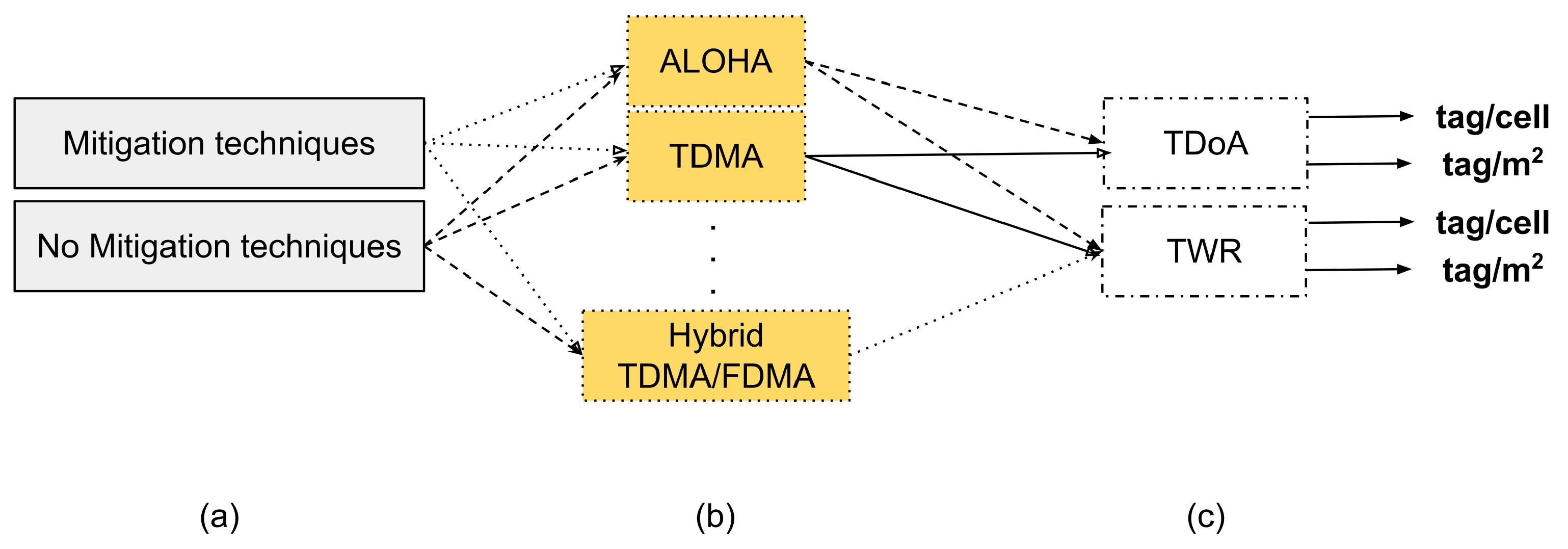
4. Localization Schemes and MAC Considerations
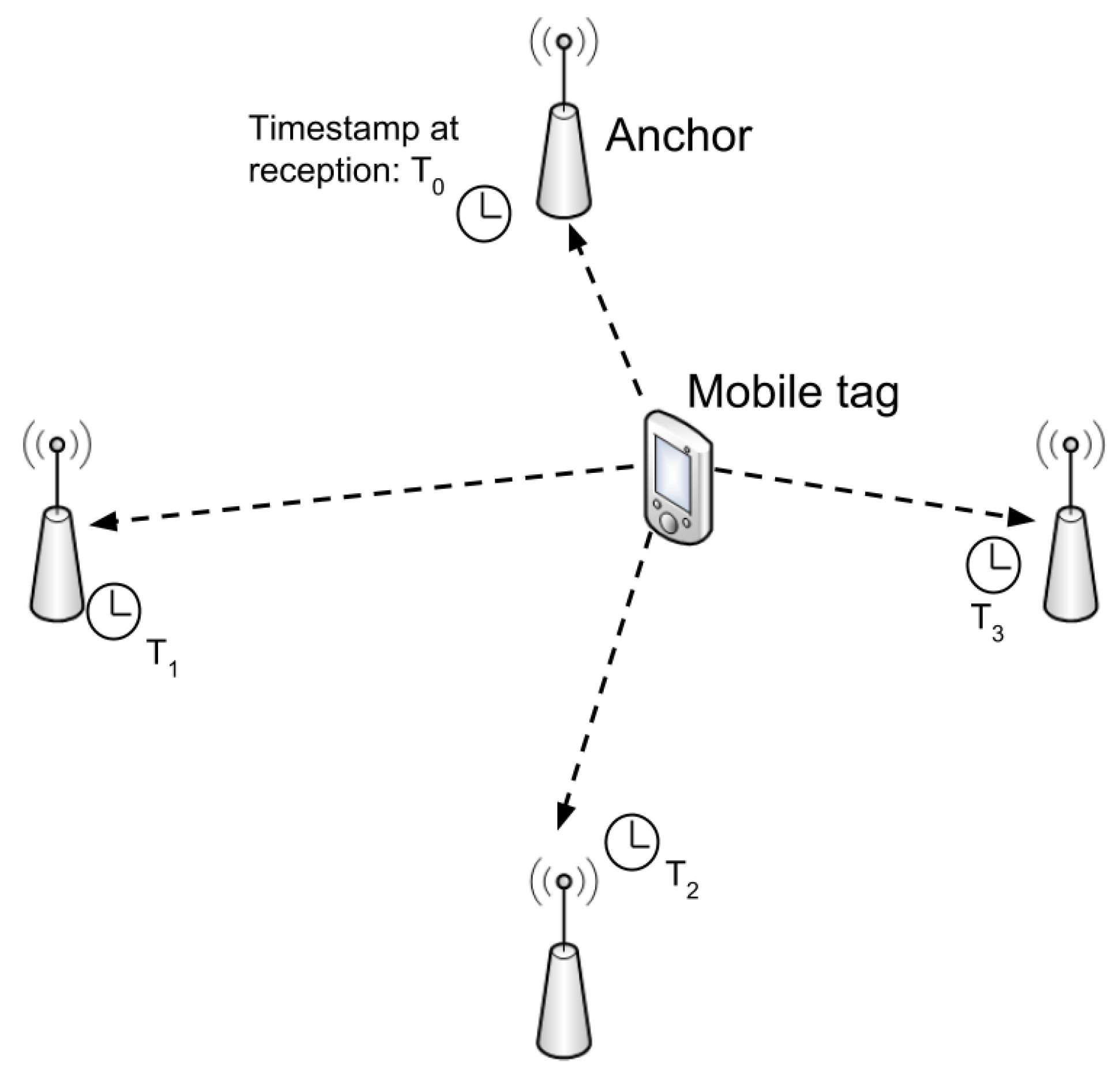
4.1. Time Difference of Arrival
- Tags need to send only one packet per position estimate, decreasing energy consumption.
- The server has more computational power than the infrastructure/mobile nodes, resulting in faster position estimation.
- All anchors in range can be used for positioning, so we obtain more accurate results.
- Anchors must be synchronized accurately, which causes synchronization beacons overhead.
- The calculated positions are unknown to the tag, so the estimated position must be communicated via a second network.
- Since the mobile tags are only transmitting and not receiving, data aggregation or collaborative localization is not possible.
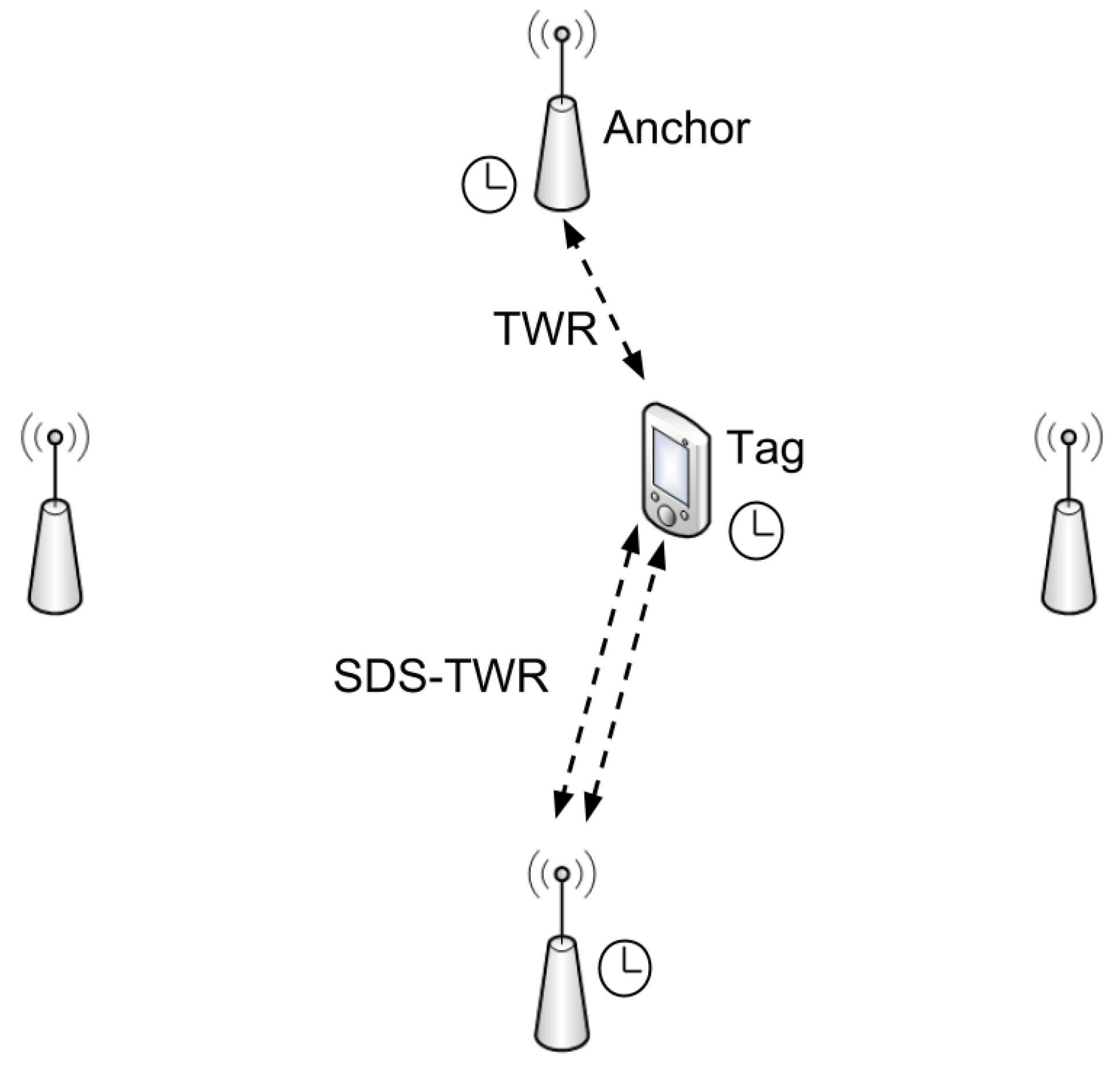
4.2. Two-Way Ranging
- Location could be computed by the mobile nodes.
- Anchors do not have to be synchronized.
- More energy consumption.
- More complex implementation, e.g., selecting the best anchors set, roaming management.
- More messages required for localization.
4.3. MAC Considerations
4.3.1. ALOHA
4.3.2. TDMA
4.3.3. Hybrid TDMA/FDMA
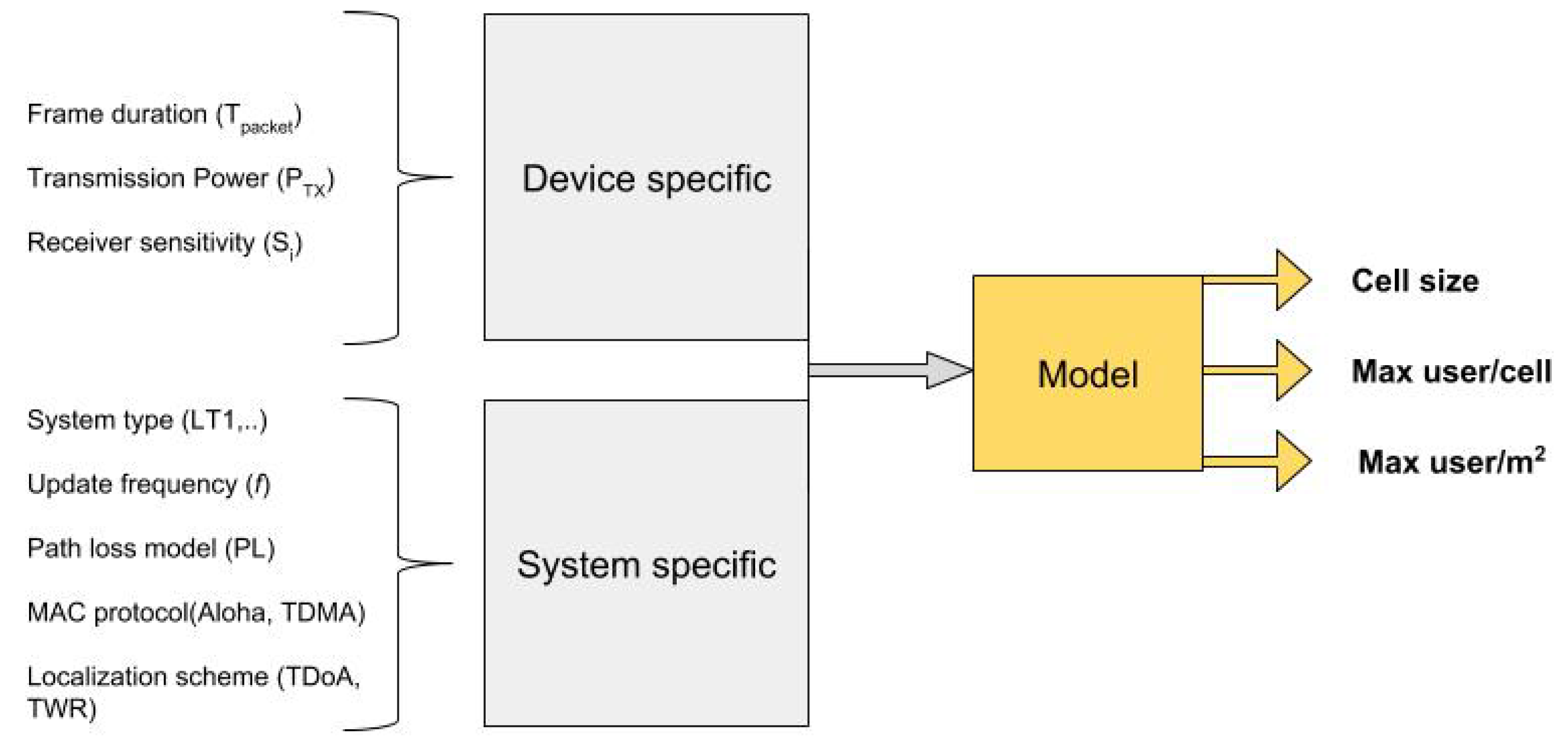
5. Scalability Model
5.1. Model Steps
5.1.1. Analyze system requirements
- Specify the type of system, e.g., LT1, LT2 or LAES. Implications of this are explained in Section 3.
- Specify the radio channel, e.g., 6 channels are available with DW1000.
- Upon previous decisions, investigate possible mitigation techniques effects. DAA and LDC are describe in Section 3.1 and Section 3.2, respectively.
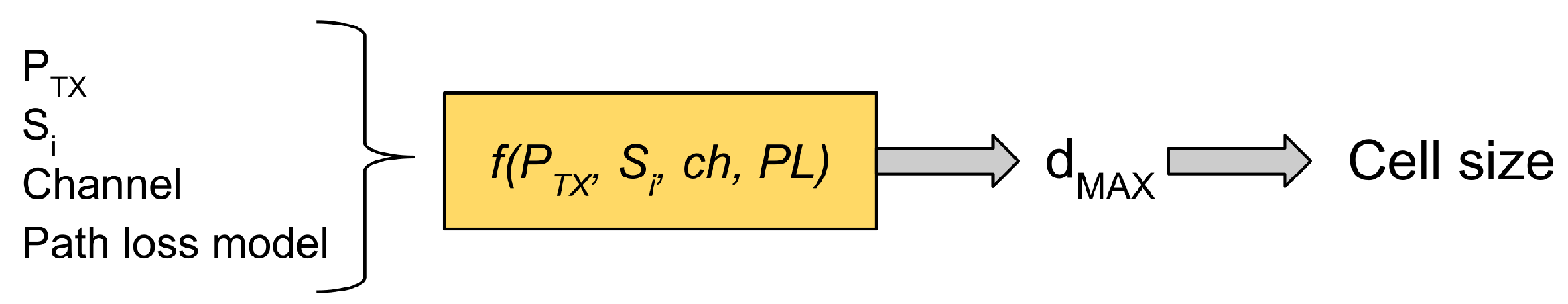
5.1.2. Achievable Range
5.1.3. Allocate System Resources
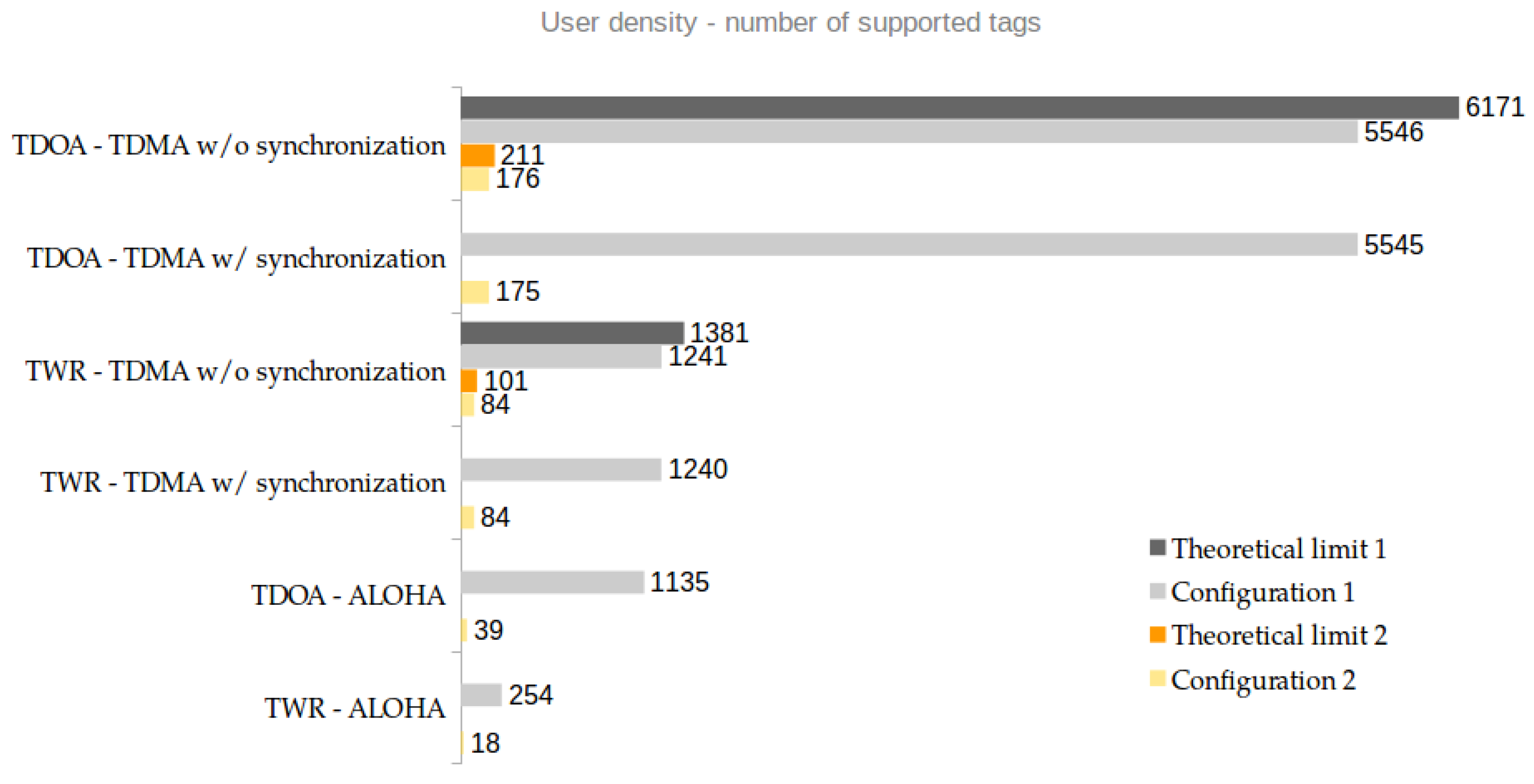
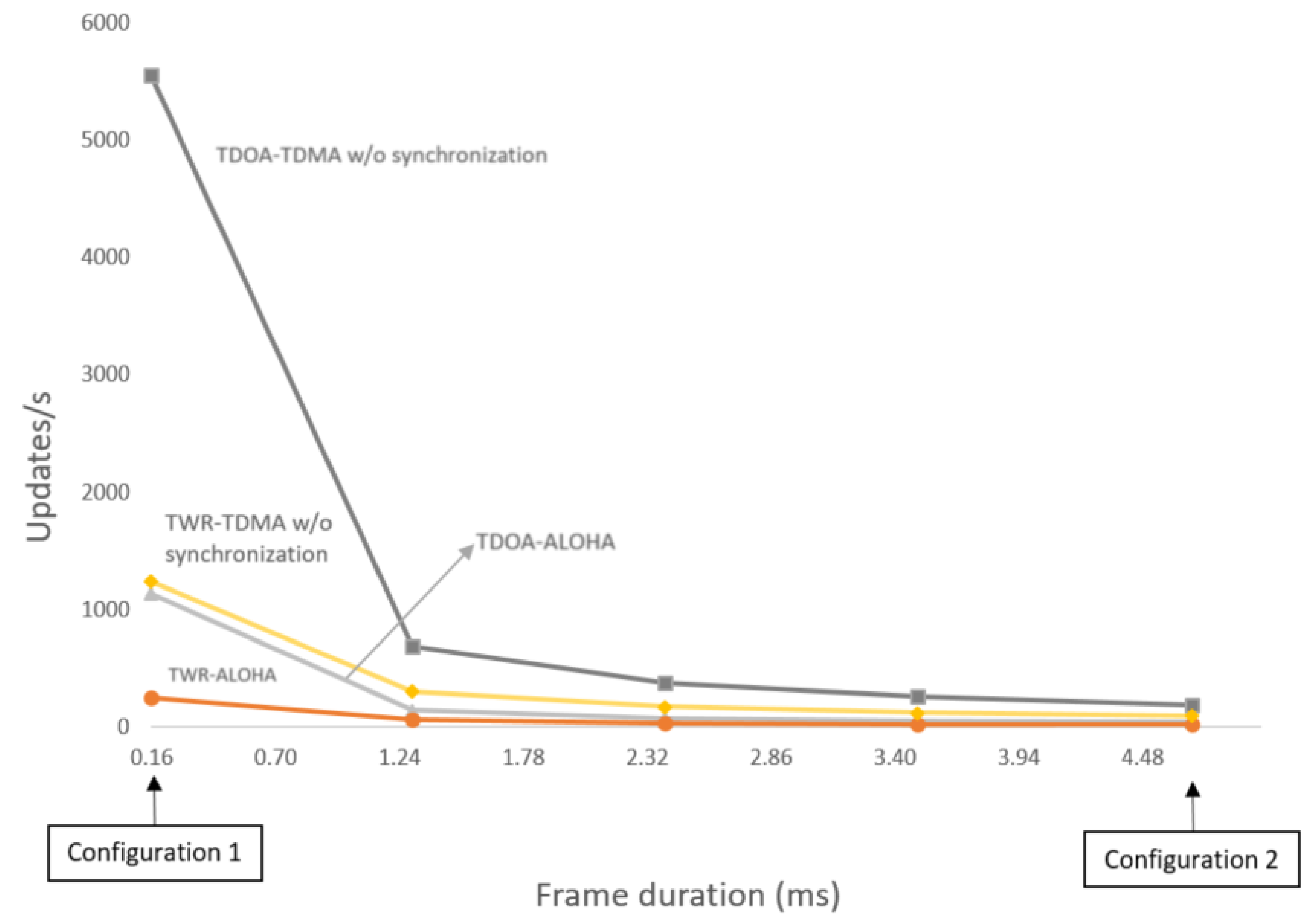
6. Application of the Scalability Model
- System type: LT1
- Channel: 5 (center frequency = 6489.6 MHz and bandwidth = 500 MHz)
- bitrate: 6.81 Mbps
- Preamble: 128 symbols
- PRF: 16 MHz
- Payload: 3 bytes
- Number of anchors: 4
- System type: LT1
- Channel: 5
- bitrate: 110 kbps
- Preamble: 4096 symbols
- PRF: 64 MHz
- Payload: 3 bytes
- Number of anchors: 4
- s
- ms
- (no synch) or
- with max payload (1023 bytes)
7. Conclusions
Author Contributions
Acknowledgments
Conflicts of Interest
Abbreviations
References
- Guvenc, I.; Gezici, S.; Sahinoglu, Z. Ultra-wideband range estimation: Theoretical limits and practical algorithms, in Ultra-Wideband. In Proceedings of the 2008 IEEE International Conference on Ultra-Wideband (ICUWB), Hannover, Germany, 10–12 September 2008. [Google Scholar]
- Silva, B.; Pang, Z.; Åkerberg, J.; Neander, J.; Hancke, G. Experimental Study of UWB-based High Precision Localization for Industrial Applications. In Proceedings of the 2014 IEEE International Conference on Ultra-WideBand (ICUWB), Paris, France, 1–3 September 2014. [Google Scholar]
- Lo, A.; Yarovoy, A.; Bauge, T.; Russell, M.; Harmer, D.; Kull, B. An Ultra-Wideband Ad Hoc Sensor Network for Real Time Indoor Localization of Emergency Responders; Delft University of Technology, Thales Research and Technology Limited and IMST GmbH: Delft, The Netherlands, 2011. [Google Scholar]
- Rowe, N.C.; Fathy, A.E.; Kuhn, M.J.; Mahfouz, M.R. A UWB Transmit-Only Based Scheme for Multi-Tag Support in a Millimeter Accuracy Localization. In Proceedings of the IEEE Topical Conference on Wireless Sensors and Sensor Networks (WiSNet), Austin, TX, USA, 20–23 January 2013. [Google Scholar]
- Barrett, T.W. History of Ultra-WideBand (UWB) Radar & Communications: Pioneers and Innovators. In Proceedings of the Progress in Electromagnetics Symposium, Cambridge, MA, USA, 5–14 July 2000. [Google Scholar]
- Koyuncu, H.; Yang, S.H. A survey of indoor positioning and object locating systems. In Proceedings of the International Conference on Innovations in Information Technology, Abu Dhabi, UAE, 25–27 April 2011; pp. 121–128. [Google Scholar]
- Ding, J.; Zhao, L.; Medidi, S.R.; Sivalingam, K.M. MAC protocols for ultra-wide-band (UWB) wireless networks: Impact of channel acquisition time. In Proceedings of the SPIE 4869, Emerging Technologies for Future Generation Wireless Communications, Boston, MA, USA, 12 November 2002. [Google Scholar]
- Gupta, A.; Mohapatra, P. A survey on Ultra Wide Band Medium Access Control Schemes. Comput. Netw. 2007, 51, 2976–2993. [Google Scholar] [CrossRef]
- Janssen, M.; Busboom, A.; Schoon, U.; Koch, C.; Colln, G.V. A Hybrid MAC Layer for Localization and Data. In Proceedings of the IEEE 17th Conference on Emerging Technologies and Factory Automation (ETFA), Krakow, Poland, 17–21 September 2012. [Google Scholar]
- Subramanian, A.; Lim, J.G. A Scalable UWB Based Scheme for Localization in Wireless Networks. In Proceedings of the Conference Record of the Thirty-Ninth Asilomar Conference on Signals, Systems and Computers, Pacific Grove, CA, USA, 30 October–2 November 2005. [Google Scholar]
- Kuhn, M.J.; Mahfouz, M.R.; Turnmire, J.; Wang, Y.; Fathy, A.E. A Multi-Tag Access Scheme for Indoor UWB Localization Systems used in Medical Environments. In Proceedings of the 2011 IEEE Topical Conference on Biomedical Wireless Technologies, Networks, and Sensing Systems (BioWireleSS), Phoenix, AZ, USA, 16–19 January 2011. [Google Scholar]
- Kolakowski, M.; Djaja-Josko, V. TDoA-TWR based positioning algorithm for UWB localization system. In Proceedings of the 2016 21st International Conference on Microwave, Radar and Wireless Communications (MIKON), Krakow, Poland, 9–11 May 2016. [Google Scholar]
- Hammer, F.; Yudanto, R.; Neumann, K.; Pichler, M.; Cockx, J.; Niestroj, C.; Petré, F. Performance Evaluation of 3D-Position Estimation Systems. IEEE Sens. J. 2016, 16, 6416–6424. [Google Scholar] [CrossRef]
- Ridolfi, M.; Van de Velde, S.; Steendam, H.; De Poorter, E. WiFi Ad-Hoc Mesh Network and MAC Protocol Solution for UWB Indoor Localization System. In Proceedings of the 23rd IEEE Symposium on Communications and Vehicular Technology in the Benelux (SCVT), Mons, Belgium, 22 November 2016. [Google Scholar]
- Alcock, P.; Roedig, U.; Hazas, M. Combining Positioning and Communication Using UWB Transceivers. In Proceedings of the 5th IEEE International Conference, DCOSS 2009, Marina del Rey, CA, USA, 8–10 June 2009. [Google Scholar]
- OpenRTLS. Available online: https://openrtls.com/ (accessed on 15 January 2018).
- sewio. Available online: https://www.sewio.net/ (accessed on 15 January 2018).
- BeSpoon. Available online: http://bespoon.com/ (accessed on 15 January 2018).
- Time Domain. Available online: https://timedomain.com/ (accessed on 18 May 2018).
- Monica, S.; Ferrari, G. Low-complexity UWB-based collision avoidance system for automated guided vehicles. ICT Express 2016, 2, 53–56. [Google Scholar] [CrossRef][Green Version]
- Bai, Y.; Lu, X. Research on UWB Indoor Positioning Based on TDoA Technique. In Proceedings of the 2009 9th International Conference on Electronic Measurement & Instruments, Beijing, China, 16–19 August 2009. [Google Scholar]
- Djaja-Josko, V.; Kolakowski, J. A new method for wireless synchronization and TDoA error reduction in UWB positioning system. In Proceedings of the 2016 21st International Conference on Microwave, Radar and Wireless Communications (MIKON), Krakow, Poland, 9–11 May 2016. [Google Scholar]
- McElroy, C.; Neirynck, D.; McLaughlin, M. Comparison of wireless clock synchronization algorithms for indoor location systems. In Proceedings of the 2014 IEEE International Conference on Communications Workshops (ICC), Sydney, Australia, 10–14 June 2014. [Google Scholar]
- De Nardis, L.; Di Benedetto, M.G. Medium Access Control Design for UWB communication systems. J. Commun. Netw. 2003, 5, 386–393. [Google Scholar] [CrossRef]
- IEEE Standard for Local and Metropolitan Area Networks–Part 15.4: Low-Rate Wireless Personal Area Networks (LR-WPANs). Available online: https://standards.ieee.org/findstds/standard/802.15.4-2011.html (accessed on 25 January 2018).
- Abramson, N. The ALOHA system—Another Alternative for Computer Communications. In Proceedings of the Fall Joint Computer Conference, Houston, TX, USA, 17–19 November 1970. [Google Scholar]
- ScenSor DW1000. Available online: http://www.decawave.com/products/ dw1000 (accessed on 17 January 2018).
- Buehrer, R.M.; Davis, W.A.; Safaai-Jazi, A.; Sweeney, D. Characterization of the ultra-wideband channel. In Proceedings of the IEEE Conference on Ultra Wideband Systems and Technologies, Reston, VA, USA, 16–19 November 2003; pp. 26–31. [Google Scholar]


| Solution | Approach | User Density | Other Notes |
|---|---|---|---|
| Subramanian and Lim, 2005 [10] | RSSI distributed localization | 200 tags | Results of simulation |
| Khun et al.; 2011 [11] | TDoA | 30 tags | Real life experiments with TDMA protocol |
| Kolakpwski and Djaja-Josko, 2016 [12] | Hybrid TDoA-TWR | Not evaluated | Improved system accuracy |
| Monica and Ferrari, 2016 [20] | TWR | 22 tags | Industrial warehouse |
| OpenRTLS [16] | TDoA, TWR | 7500 updates/s | Communication range 20 m |
| Sewio [17] | TDoA | 1000 updates/s | Communication range 30 m |
| Be Spoon [18] | TDoA, TWR, AoA | 750 updates/s | Office like environment |
| Time Domain [19] | TWR | Unknown | Proprietary MAC protocols |
| Frequency (GHz) | Maximum Mean Power Spectral Density (e.i.r.p.) (dBm/MHz) | ||
|---|---|---|---|
| LT1 | LT2 | LEAS | |
| −90 | −90 | −90 | |
| −85 | −85 | −85 | |
| −70 | −70 | −70 | |
| −70 | −70 (−41.3 with DAA) 1 | −70 (−41.3 with DAA) 1 | |
| −80 | −41.3 1,2 (see note 1 for fixed outdoor) | −21.3 1 | |
| −70 | −41.3 1,2 (see note 1 and 3 for outdoor) | −21.3 1 | |
| −70 | −41.3 1,2 (see note 1 and 3 for outdoor) | −41.3 1 | |
| −70 | −70 | −70 | |
| −41.3 | −70 | −70 | |
| −64 (−41.3 with DAA) | −70 | −70 | |
| −65 | −70 | −70 | |
| f >10.6 | −85 | −85 | −85 |
| Frequency (GHz) | Maximum Peak Power Spectral Density (e.i.r.p.) (dBm in 50 MHz) | ||
|---|---|---|---|
| LT1 | LT2 | LEAS | |
| −50 | −50 | −50 | |
| −45 | −45 | −45 | |
| −36 | −36 | −36 | |
| −36 | −36 (0 with DAA) 1 | −36 (0 with DAA) 1 | |
| −40 | 0 1,2 (see note 1 for fixed outdoor) | 20 1 | |
| −60 | 0 1,2 (see note 1 and 3 for outdoor) | 20 1 | |
| −60 | 0 1,2 (see note 1 and 3 for outdoor) | 0 1 | |
| −30 | −30 | −30 | |
| 0 | −30 | −30 | |
| −25 (0 with DAA) | −70 | −30 | |
| −25 | −30 | −30 | |
| f > 10.6 | −45 | −45 | −45 |
| Parameters | Restrictions |
|---|---|
| Max transmitter on time | 5 ms |
| Mean transmitter off time | ≥38 ms (averaged over 1 s) |
| Sum transmitter off time | >950 ms per second |
| Sum transmitter on time | <18 s per hour |
| Time Difference of Arrival | Two Way Ranging | |
|---|---|---|
| Anchors Synchronization | Yes | No |
| Energy Overhead | Low | High |
| Hybrid MAC Protocol Flexibility | Low | High |
| Position Information Availability | At Infrastructure Side | At Both Sides |
| Symbol | Variable Name | Unit | |
|---|---|---|---|
| Radio | Frame duration | ms | |
| Synchronization header (SHR) duration | ms | ||
| PHY header (PHR) duration | ms | ||
| PHY service data unit duration | ms | ||
| Preamble length | symbols | ||
| Start of frame delimiter (SFD) length | bits | ||
| Reed Solomon bits | bits | ||
| Data length | bits | ||
| SHR symbols duration | ms | ||
| PHR symbols duration | ms | ||
| Data symbols duration | ms | ||
| Pulse repetition frequency | Hz | ||
| Transmission power | dBm | ||
| Receiver sensitivity | dBm | ||
| Channel number | unitless | ||
| Path loss model | unitless | ||
| MAC | Reply time in TWR | ms | |
| Transmission duration | ms | ||
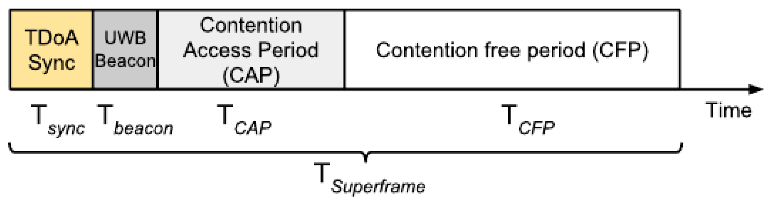
| Synchronization beacon duration | ms | ||
| Beacon duration | ms | ||
| Contention Access Period (CAP) duration | ms | ||
| Contention Free Period (CFP) duration | ms | ||
| Superframe duration | ms | ||
| Resources available | unitless | ||
| Number of anchors | unitless | ||
| Number of message exchanges | unitless | ||
| N | Number of supported tags | unitless | |
| Position update frequency | Hz | ||
| LDC | Transmitter on time | ms | |
| Transmitter off time | ms | ||
| DAA | Power level threshold | dBm | |
| Transmit power of victim system | dBm | ||
| I | Minimum needed isolation | dBm |
| Data Rate (Mbps) | PRF (MHz) | SHR (ns) | PHR (ns) | Data (ns) |
|---|---|---|---|---|
| 0.11 | 16 | 993.59 | 8205.13 | 8205.13 |
| 0.11 | 64 | 1017.63 | 8205.13 | 8205.13 |
| 0.85 | 16 | 993.59 | 1025.64 | 1025.64 |
| 0.85 | 64 | 1017.63 | 1025.64 | 1025.64 |
| 6.81 | 16 | 993.59 | 1025.64 | 128.21 |
| 6.81 | 64 | 1017.63 | 1025.64 | 128.21 |
© 2018 by the authors. Licensee MDPI, Basel, Switzerland. This article is an open access article distributed under the terms and conditions of the Creative Commons Attribution (CC BY) license (http://creativecommons.org/licenses/by/4.0/).
Share and Cite
Ridolfi, M.; Van de Velde, S.; Steendam, H.; De Poorter, E. Analysis of the Scalability of UWB Indoor Localization Solutions for High User Densities. Sensors 2018, 18, 1875. https://doi.org/10.3390/s18061875
Ridolfi M, Van de Velde S, Steendam H, De Poorter E. Analysis of the Scalability of UWB Indoor Localization Solutions for High User Densities. Sensors. 2018; 18(6):1875. https://doi.org/10.3390/s18061875
Chicago/Turabian StyleRidolfi, Matteo, Samuel Van de Velde, Heidi Steendam, and Eli De Poorter. 2018. "Analysis of the Scalability of UWB Indoor Localization Solutions for High User Densities" Sensors 18, no. 6: 1875. https://doi.org/10.3390/s18061875
APA StyleRidolfi, M., Van de Velde, S., Steendam, H., & De Poorter, E. (2018). Analysis of the Scalability of UWB Indoor Localization Solutions for High User Densities. Sensors, 18(6), 1875. https://doi.org/10.3390/s18061875