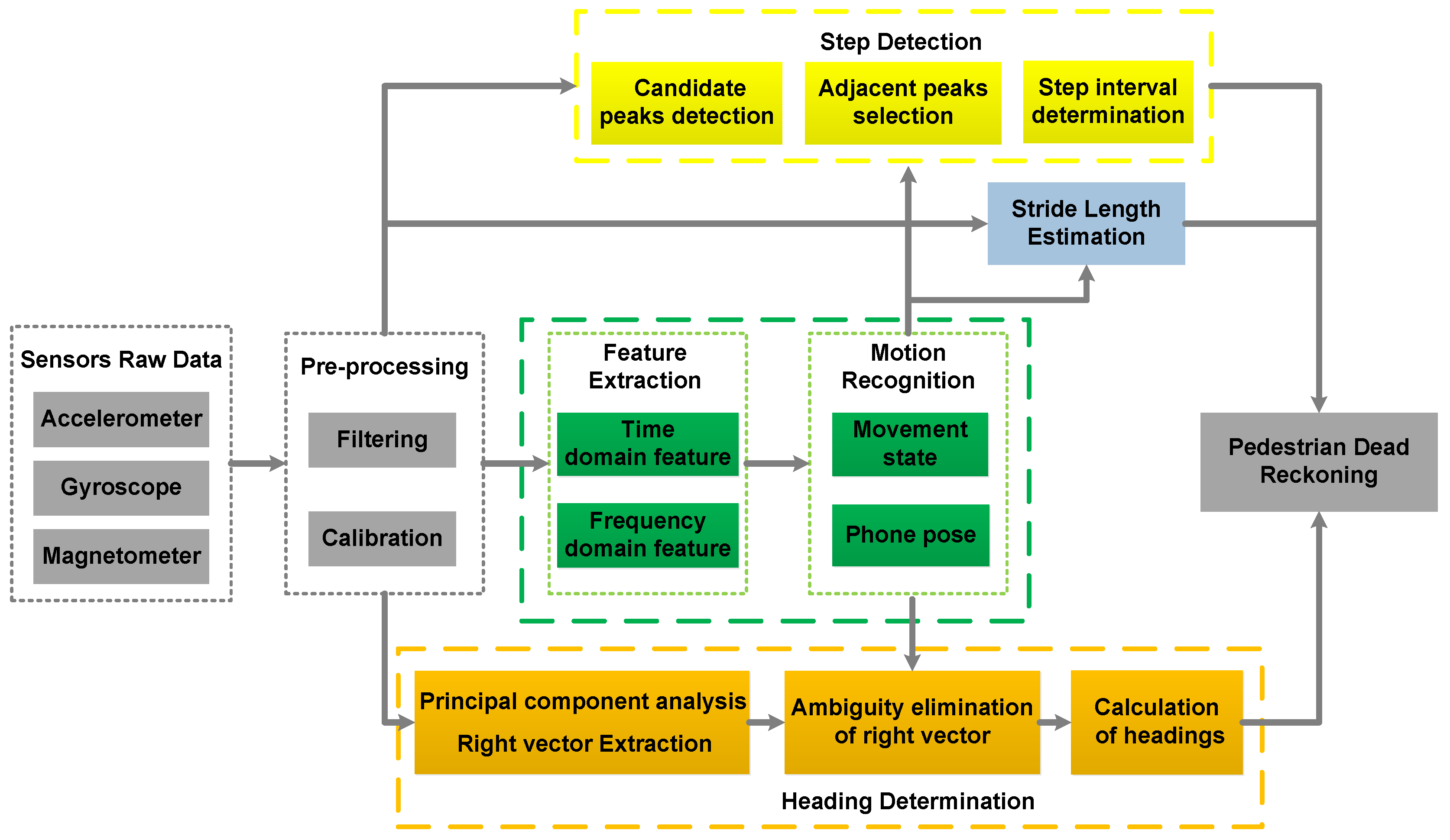
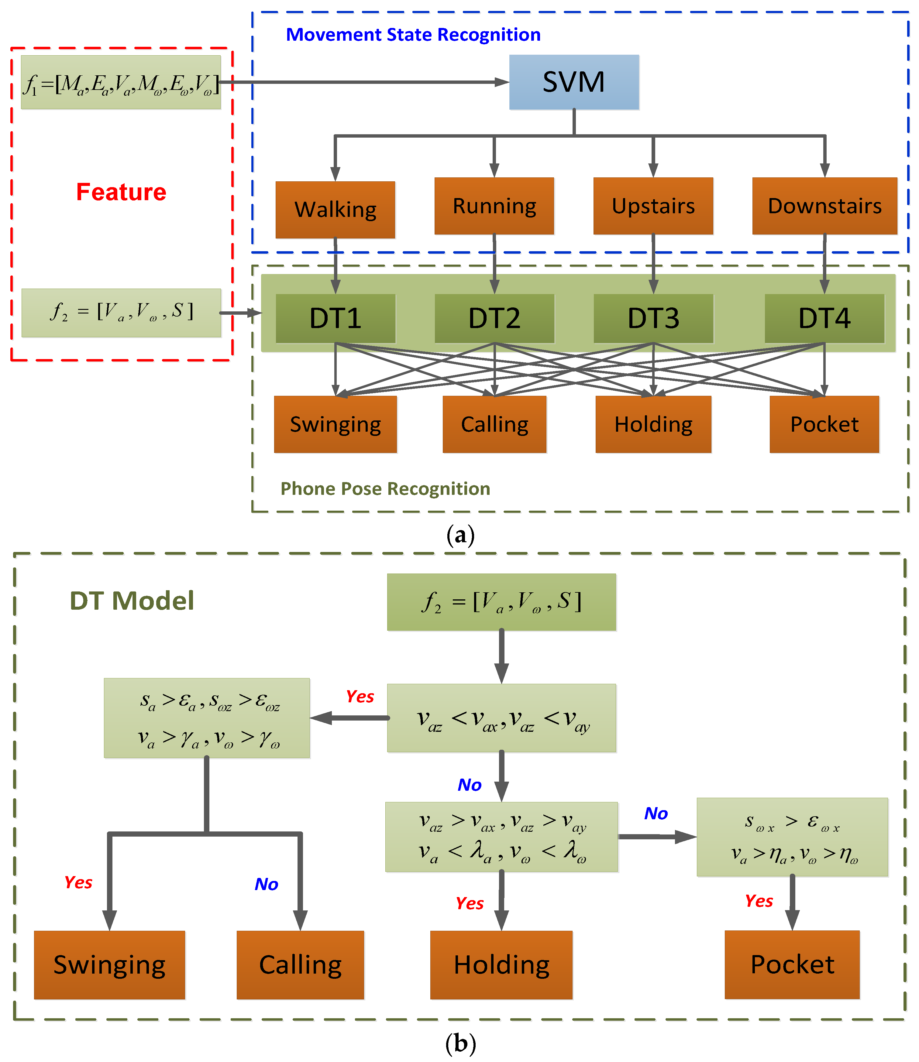
The data from accelerometers and gyroscopes show various characteristics in different movement states and phone poses. Therefore, based on the results of the classification, a flexible PDR algorithm for multi-motion modes is proposed, including step detection, stride length estimation and heading determination. The equation of the PDR system is:
where
X and
Y are the coordinates in the east and north,
L is the stride length,
is the heading angle during one stride interval, and
k denotes the index of pedestrian’s strides.
6.1. Step Detection
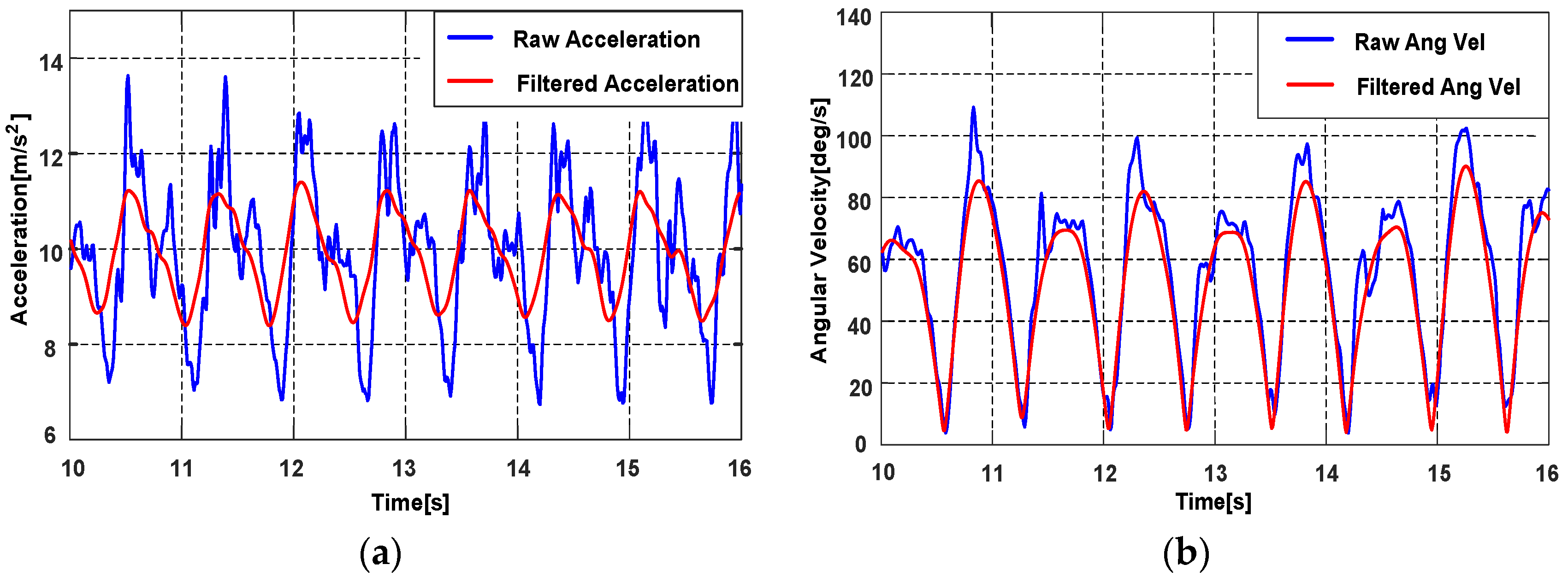
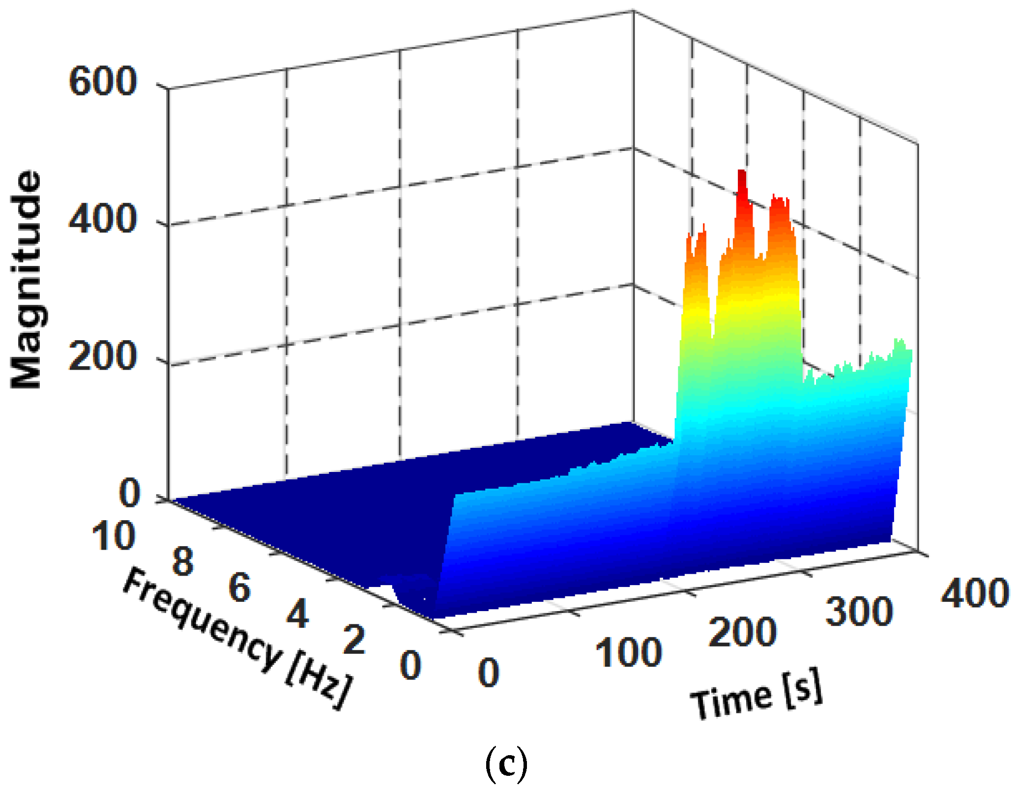
The phone produces a periodic motion with the steps while a pedestrian is walking, and the accelerometer data can reflect the step characteristics. The change of device’s attitude will influence the values of the acceleration on three axes, to avoid the influence, the magnitude of the acceleration
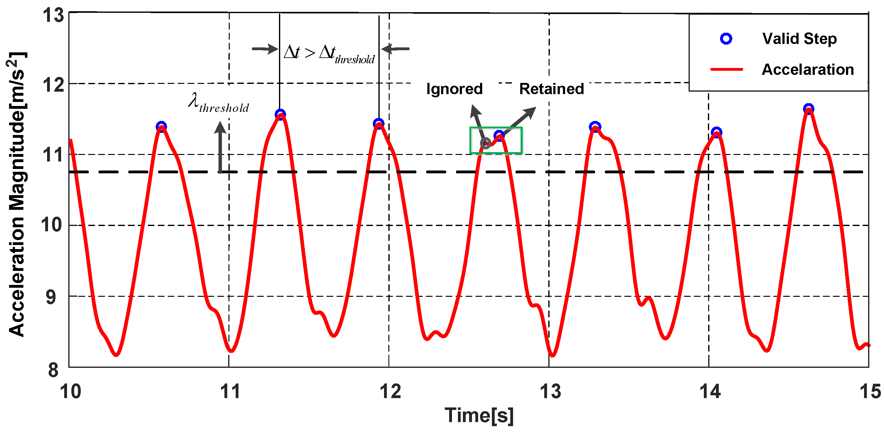
in Equation (1) is chosen as the norm for step detection. The magnitudes of accelerations in Holding are shown in
Figure 11, the acceleration magnitude presents a sinusoidal wave and the peaks represent the probable steps of pedestrian. For different movement states and phone poses, the accelerations are also different. To detect the steps accurately, the parameters of algorithm are adjusted for different movement states and phone poses, the step detection algorithm in this paper consists of three modules:
- 1.
Candidate peaks detection
The core of the step detection algorithm is to find the peaks that can represent the actual steps of pedestrian. Thus, a candidate peak threshold is needed to filter out the peaks caused by pedestrian irregular motions, is obtained by analysis of the experimental data. Since the acceleration magnitude varies widely in different movement states and phone poses, the value of peak threshold is adjusted with the consideration of different motions. The peaks greater than candidate peak threshold are regarded as the candidate peaks and the others are the invalid peaks.
- 2.
Adjacent peaks selection
Although the acceleration signals have been filtered, there are still false peaks in the filtered signal. Therefore, the adjacent peaks selection mechanism is added. We define an adjacent peaks window with a small size. If there are two or more peaks within the window, the peak with larger magnitude is retained, the peak with smaller magnitude is regarded as a false peak and ignored.
- 3.
Step (stride) interval determination
After the above steps, we consider the time interval
between two consecutive candidate peaks. Pedestrians’ step frequency is less than 5 Hz [
39], thus the minimum step interval threshold
is set to 0.2 s. If the time interval
satisfy the threshold
, the peak is the valid peak and represents one step of the pedestrian. It should be noted that the phone presents pendulum motion in Swinging and Pocket. Therefore, each valid peak represents two steps in Swinging and Pocket, denoted as a stride. The stride interval is adopted in Swinging and Pocket, the size of the minimum stride interval threshold is two times that of the minimum step interval threshold.
6.2. Stride Length Estimation
The stride length varies from person to person, it should be a variable which is related to the pedestrian. For different individuals, stride length will be affected by height, gender and walking speed [
40]. However, for the same pedestrian, stride length is mainly related to stride frequency of the pedestrian [
37]. Many estimation models have been proposed and most models are generated by using accelerometer data, including linear model, nonlinear model and artificial neural network model [
41,
42,
43,
44]. In this paper, a linear formula from [
44] is adopted to estimate pedestrian’s stride length, which is denoted as:
where
L is the stride length to be estimated.
is the stride frequency, which is the reciprocal of one stride duration and can be obtained by the step detection process.
is the variance of the accelerations during the interval of one stride.
C is a constant,
A and
B are the coefficients of the stride frequency and the acceleration variance.
A,
B and
C are the personalized parameters that need to be calibrated for each pedestrian. The variance
is different for different phone poses and the estimated stride length is also influenced. Thus, all model parameters are trained for each phone pose.
6.3. Heading Determination
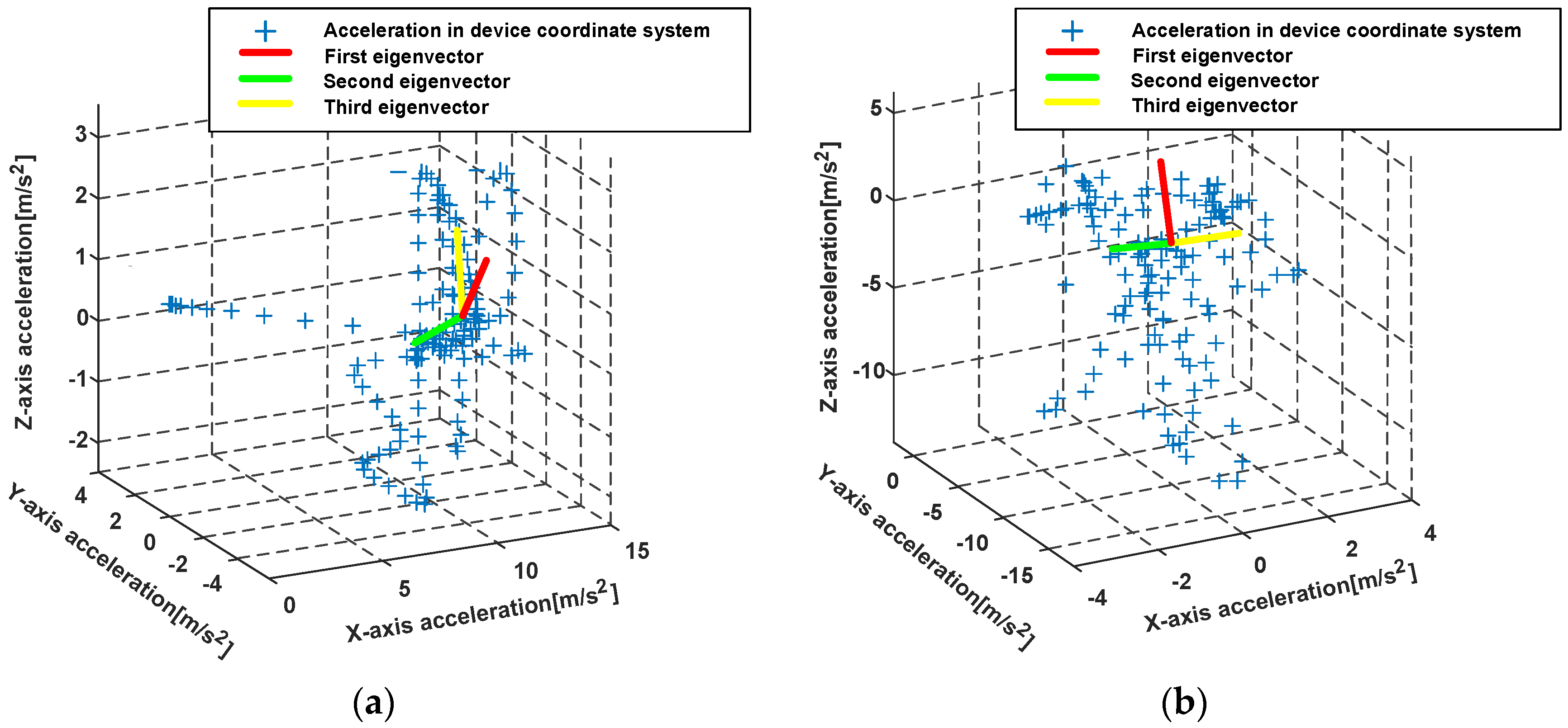
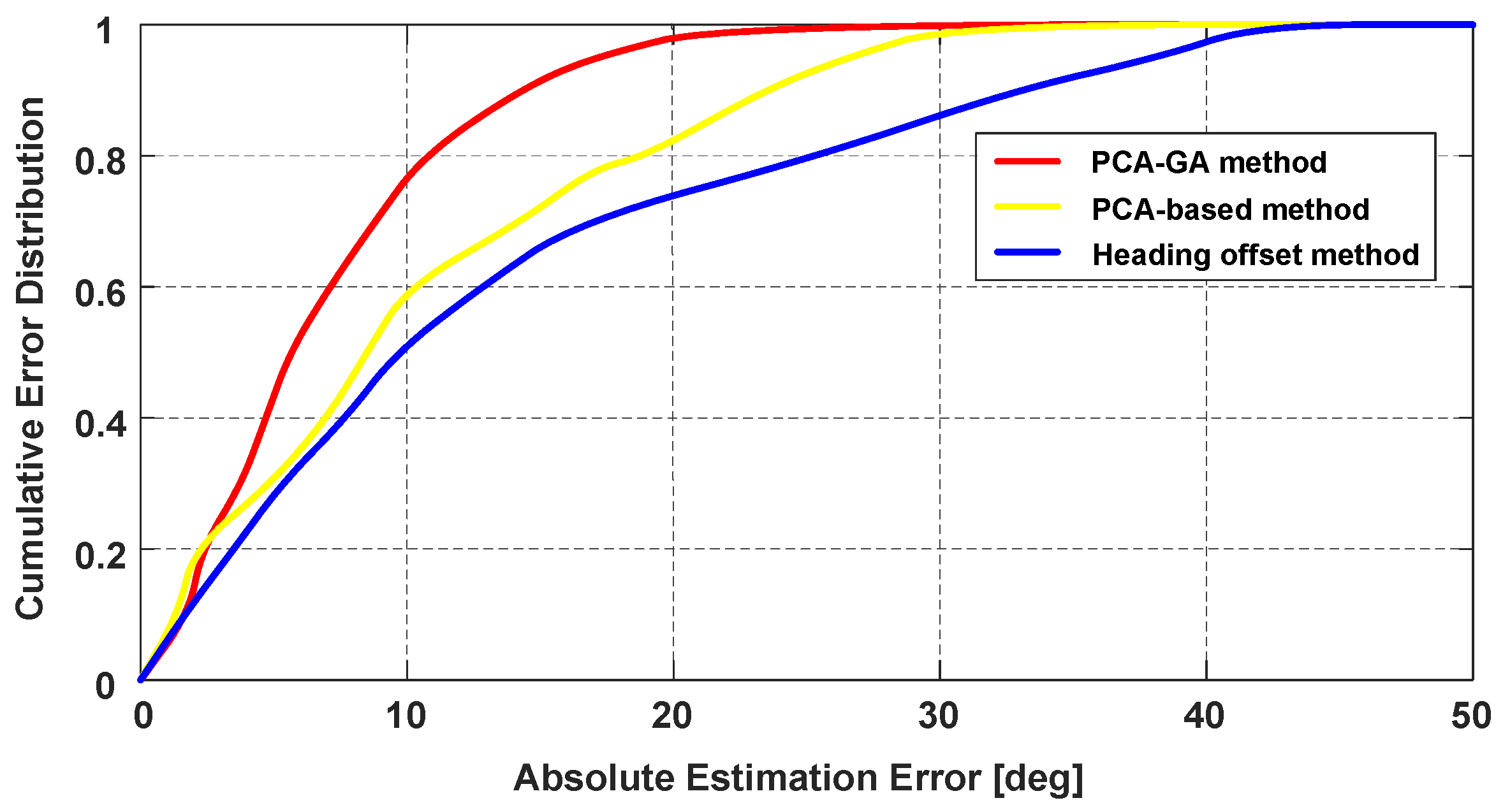
Because of the characteristics of PDR, the calculation of pedestrian’s heading angles affects the precision of localization system greatly and it is also the most difficult part in the whole PDR. For Holding and Calling, the attitude of the phone is stable relative to the body while pedestrian is walking. The heading angle offset between pedestrian’s actual direction and smartphone’s direction can be easily obtained, thus pedestrian’s heading can be determined by removing the heading offset. However, for Swinging and Pocket, the attitude of smartphone changes constantly and the heading offset is not constant. As a result, the PCA-based method is used to calculate pedestrian’s headings in literatures. The PCA-based method is based on a fact that the most variations of the horizontal accelerations are parallel to pedestrian’s direction [
35,
37,
45], thus the first eigenvector is regarded as pedestrian’s direction. In the PCA-based method, the horizontal accelerations need to be first obtained by the related vertical acceleration, the vertical acceleration is obtained while pedestrian is approximately static. However, smartphone’s attitude varies constantly in Swinging and Pocket while pedestrian is walking. More importantly, the device coordinate system varies during per stride time interval. Therefore, the obtained horizontal accelerations of one stride time interval cannot be guaranteed to be completely horizontal, and the obtained pedestrian’s direction vector will be influenced by the accelerations of the vertical plane, which will cause errors in the heading estimation.
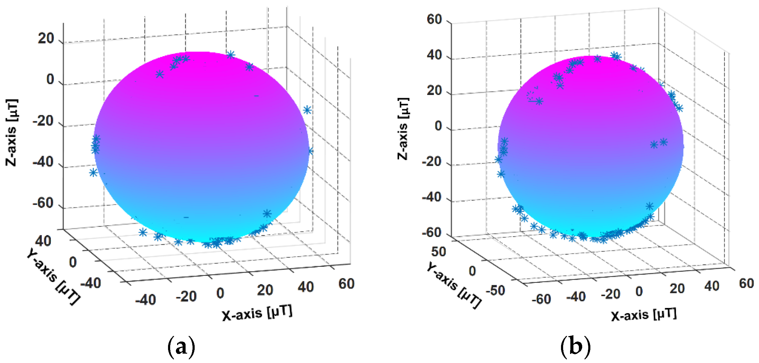
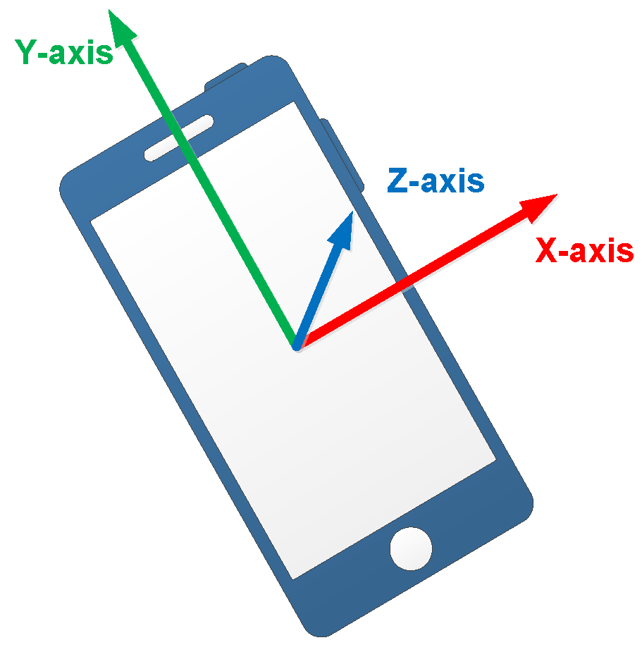
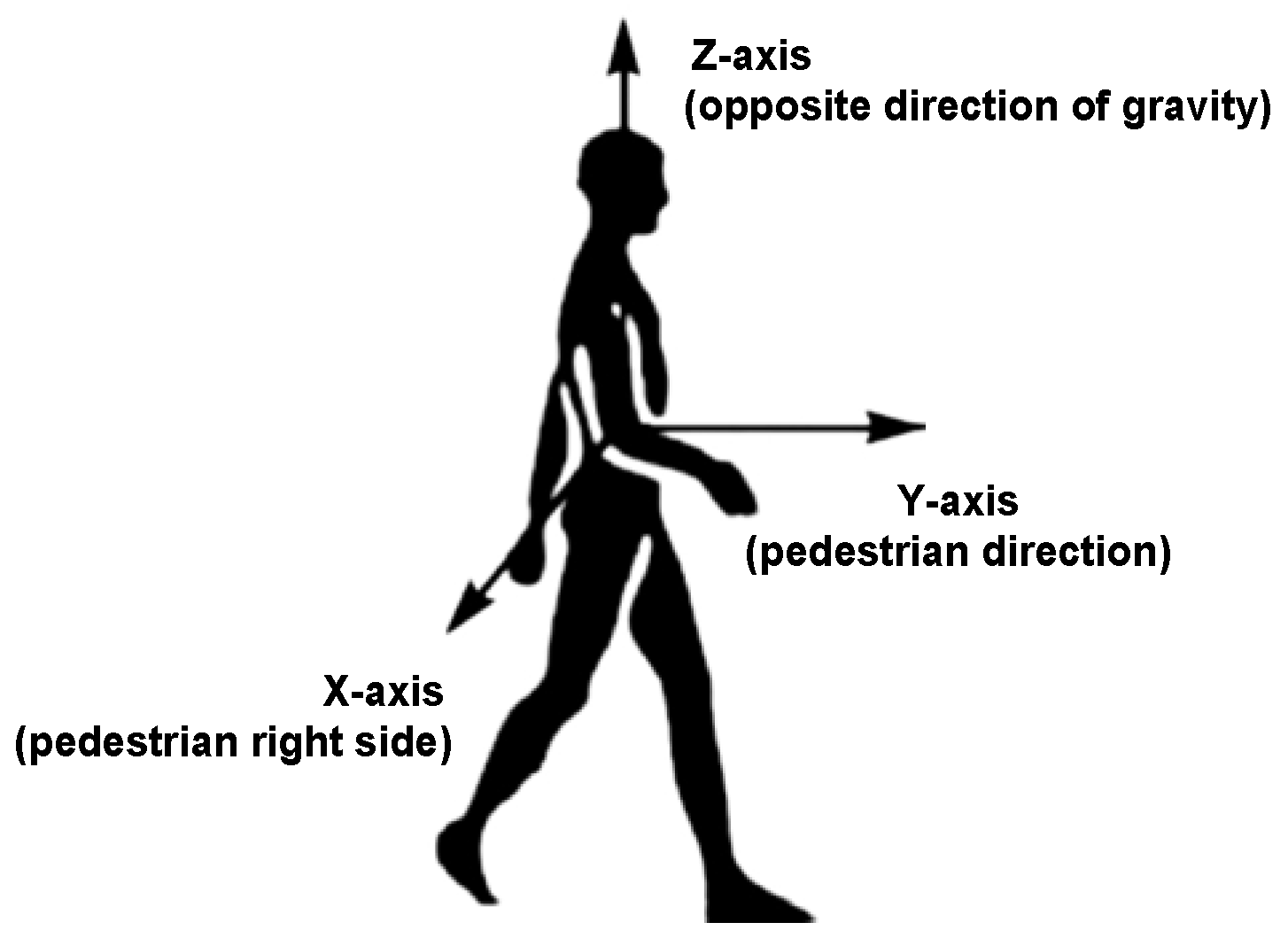
To solve the mentioned problems, we present a PCA-based method with global accelerations (PCA-GA) to infer pedestrian’s headings for Pocket and Swinging. The global accelerations are the accelerations of three-axis in device coordinate system, which avoids the calculation of the horizontal accelerations. Through our observations, we found that, during walking, the position change of smartphone in X-axis of pedestrian coordinate system is minimal. The pedestrian coordinate system is depicted in
Figure 12, where Y-axis points to the direction of pedestrians walking, X-axis points to the right side of pedestrian’s body and Z-axis points to opposite direction of gravity. The PCA-GA method is based on the fact that the least variations of the global accelerations are parallel to X-axis of pedestrian coordinate system. Therefore, the direction of the third eigenvector in PCA-GA is regarded as the initial right-vector
of the pedestrian, the right vector is in device coordinate system and perpendicular to the pedestrian’s direction in the horizontal plane. The extracted eigenvectors from the global accelerations of device coordinate system are shown in
Figure 13.
However, the right-vector
acquired from PCA-GA has the problem of 180° ambiguity [
35],
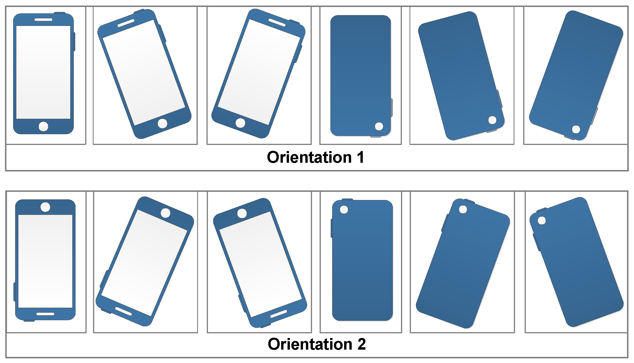
may point to right or left side of the body. According to the definition of phone poses in
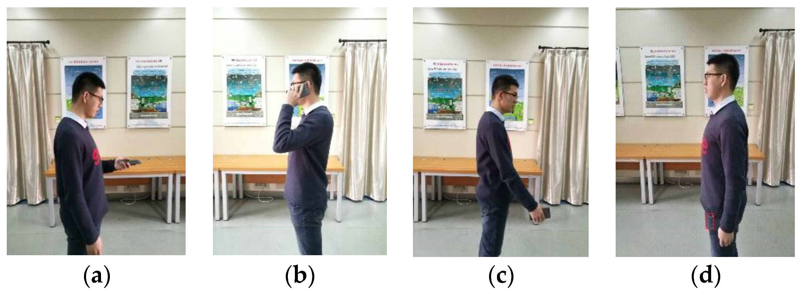
Section 5.2, we analyze the orientations of three-axis of accelerometer while the smartphone is swinging in different hands. As shown in
Table 1, by observing the acceleration value of X-axis (positive or negative), we can easily know which hand is holding the phone. Take the left-hand case as an example, Z-axis of device coordinate system is approximately to the right side of the body, thus the component
of right-vector
should be positive. If this is not satisfied, we take the opposite vector of right-vector as actual right-vector
.
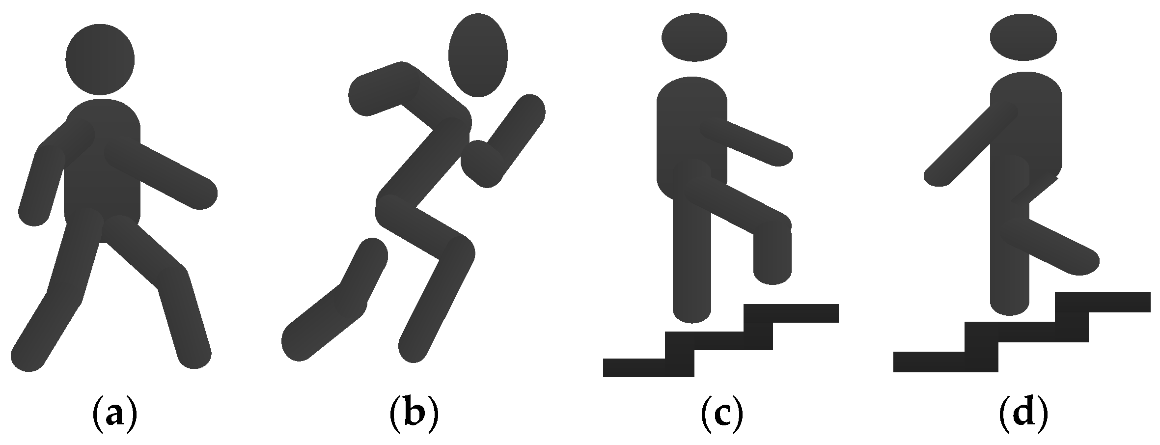
According to the definition of Pocket, the phone screen plane is approximately vertical to the ground. When the smartphone is carried in the pocket of trousers, we divide its orientations into two major categories, as shown in
Figure 14. O1 and O2 represent the smartphone’s X-axis points to right side and left side of pedestrian, respectively.
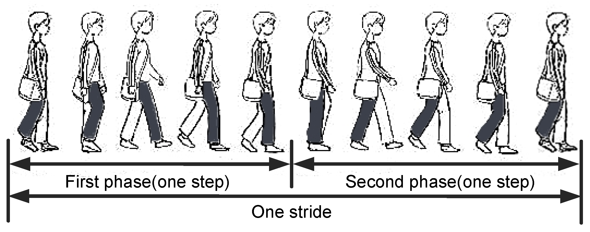
Pedestrian’s one stride can be divided into two phases as shown in
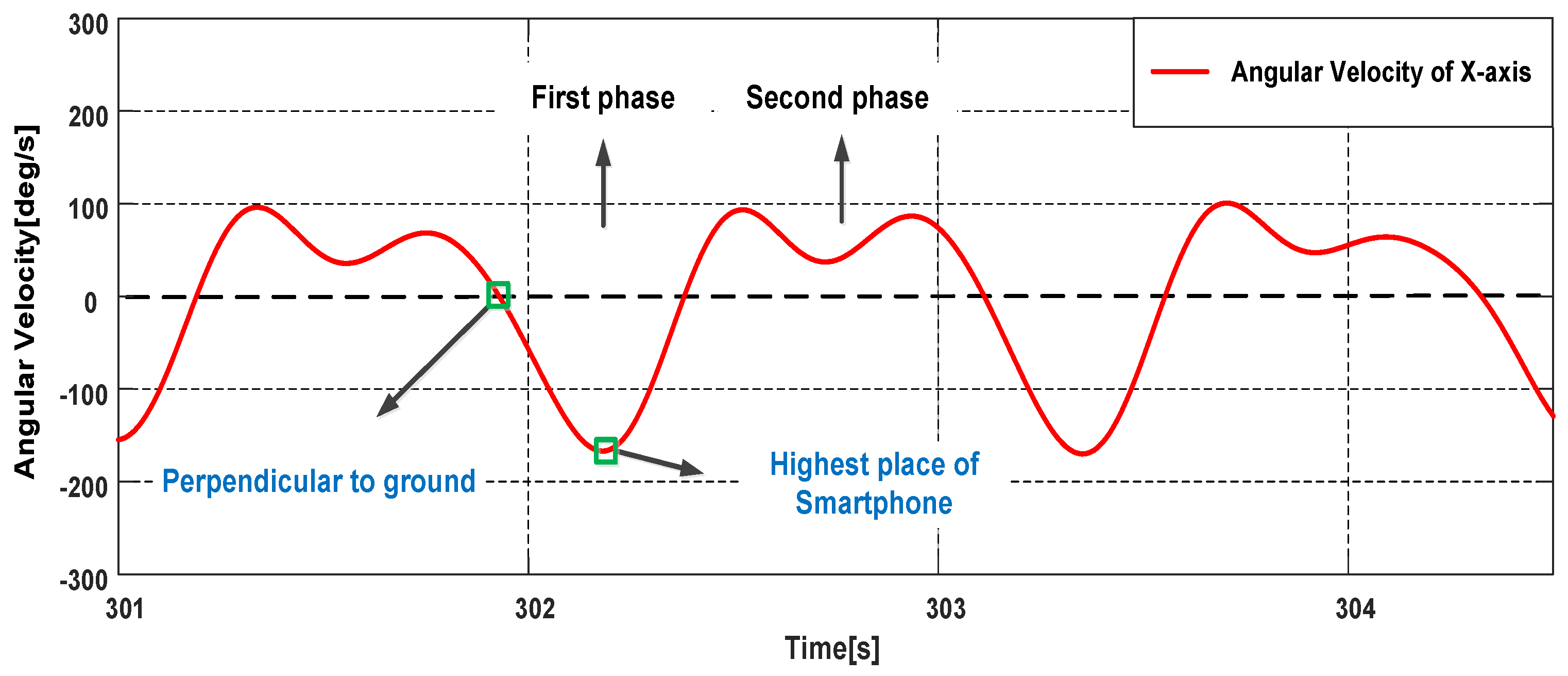
Figure 15, we describe the movement process in the case of the phone in the right pocket of trousers. Looking to the right side of the body, during the first phase: the right thigh does the counterclockwise motion to a certain height first, then begins to do the clockwise motion; during the second phase: the right thigh continue the clockwise motion until the right foot leaves the ground, then does the counterclockwise motion. The phone’s rotation generates angular velocities on X-axis of gyroscope during one stride. Take O1 as an example, looking to the right side of the body, in the first (second) phase, the angular velocities on X-axis are positive (negative) with the counterclockwise (clockwise) rotation. Because the thigh has a lifting motion in the first phase, the variation range of the angular velocities on X-axis in the first phase is greater. Therefore, we can infer the smartphone’s orientation by the angular velocities on X-axis. As shown in
Figure 16, the absolute value of the trough is greater than the peak in a stride period, thus the smartphone’s orientations belong to O2. In this case, the component
of the right-vector
should be negative, if this is not satisfied, we take the opposite vector of the right-vector as the actual right-vector
.
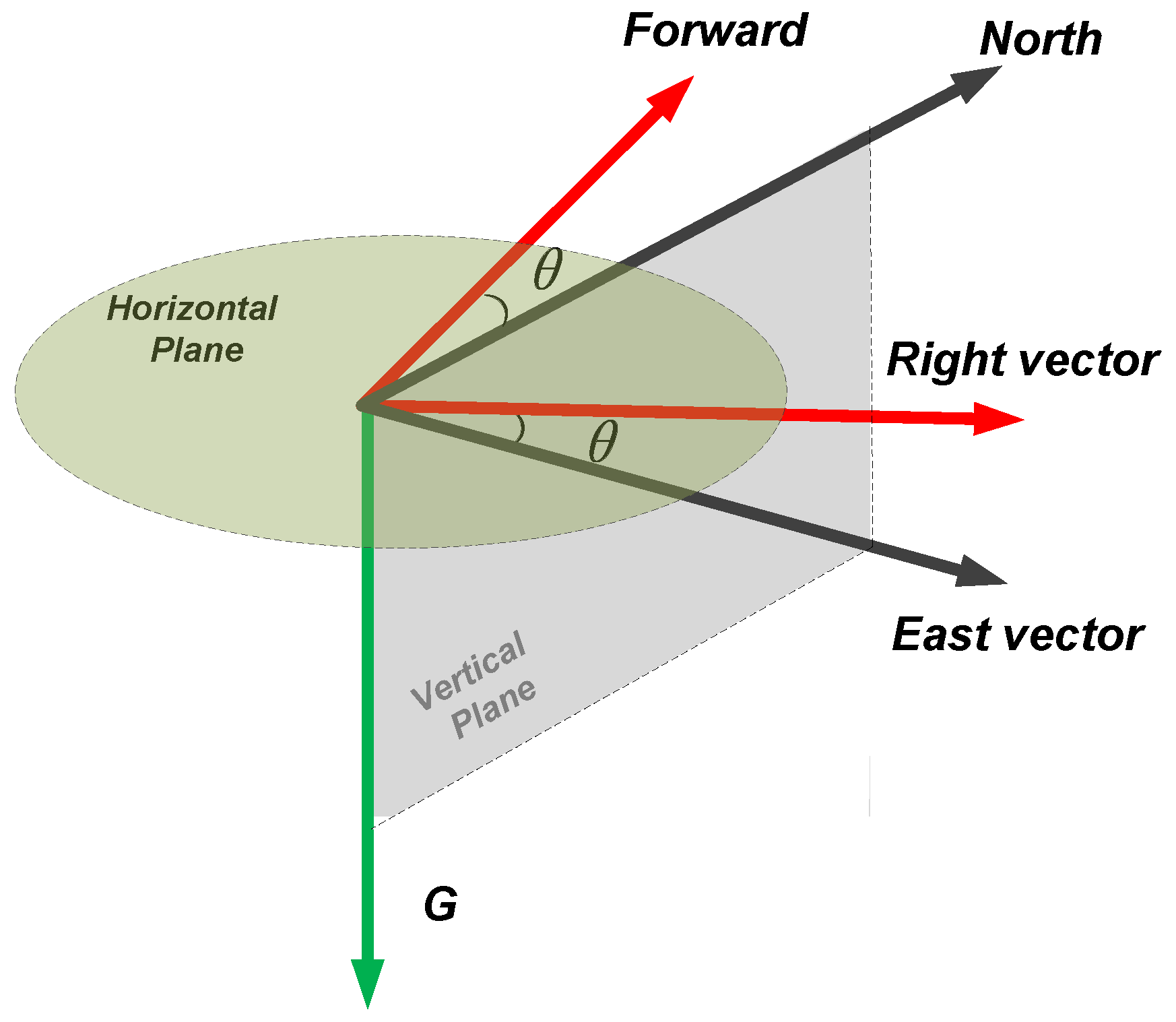
The heading angle is calculated by the right vector
and the east vector
(mentioned in the following), we first project the right-vector and the magnetic vector onto the horizontal plane. It is realized by the estimated gravity vector [
46], and the estimated gravity vector is:
where
,
and
are the averages of all the measurements on the respective axis in the time interval of one stride.
The right-vector is denoted as:
where
,
and
represent the component on the respective axis of device coordinate system.
Then, vector dot product is used to calculate the projection
of
upon the estimated gravity vector
, in other words,
is the component of right vector in the vertical plane:
The horizontal component
can be obtained by the vector subtraction:
The estimated gravity vector
points to the downward and the magnetic vector
points to the north and downward in the northern hemisphere. The east vector
is perpendicular to both
and
, thus the east vector can be obtained by vector cross product [
47] in the device coordinate system. The magnetic vector is approximated by averaging the readings of magnetometer in the time interval of one stride:
where
,
and
are averages of all the measurements on the respective axis in the time interval of one stride.
As shown in
Figure 17, the red arrows represent the forward and right direction of pedestrian, the black arrows represent the horizontal component of the magnetic vector and the east vector, and the green arrow represents the estimated gravity vector. Obviously, the heading angle is the angle between the east vector and the right vector, which is obtained by vector dot product:
where the obtained heading angles are within the interval from 0 to
, and they are needed to be extended to the interval from 0 to
, it can be solved by vector cross product:
where the vector cross product
is in the same (opposite) direction as the gravity vector, when the right vector is on the right (left) side of the east vector,
is the local magnetic declination.


