Environmental Monitoring of Ancient Buildings Based on a Wireless Sensor Network

Abstract
1. Introduction
2. Materials and Methods
2.1. Hardware
2.1.1. ZigBee Nodes
2.1.2. Sensors
2.1.3. Power Supply System
2.2. System Design
2.2.1. Overall Design of the System
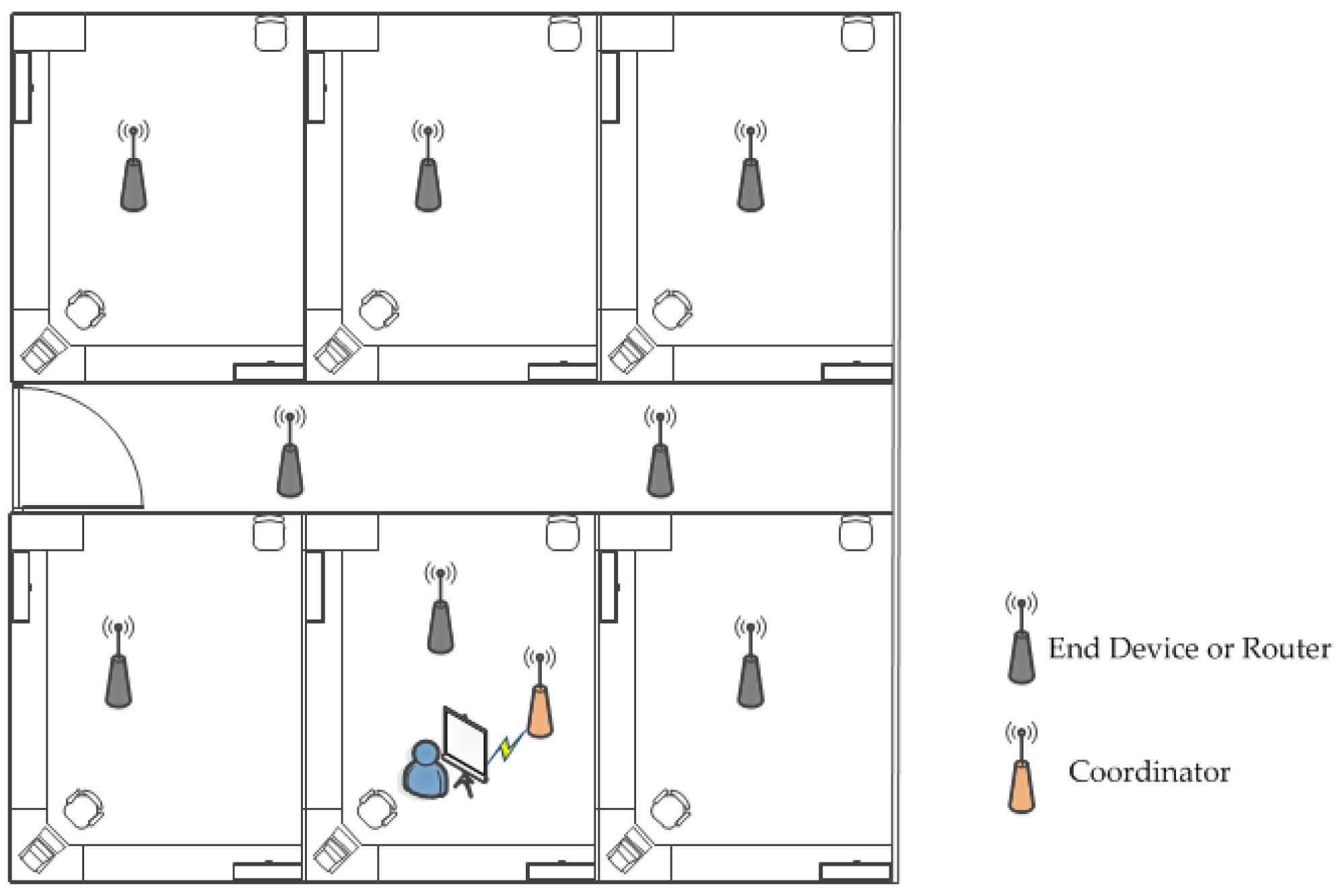
2.2.2. Network Topology
- SampleApp_Periodic_DstAddr.addrMode = (afAddrMode_t)AddrBroadcast; // broadcast.
- SampleApp_Periodic_DstAddr.endPoint = SAMPLEAPP_ENDPOINT; //Specify endpoint number.
- SampleApp_Periodic_DstAddr.addr.shortAddr = 0xFFFF; // Specify the destination network address as the broadcast address.
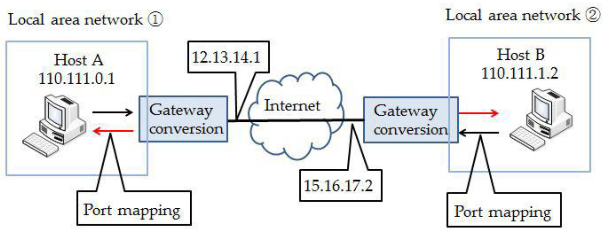
2.2.3. Remote Communication
2.3. Packaging Structure
2.3.1. Indoor Node Package Box
- Miniaturization. This is good for moving and installing, saving indoor space, and avoiding an impact on the other items in the room.
- Regionalization. Because the node contains many devices, placing the modules separately is beneficial in order to avoid the problem of entanglement between the wires.
- Ventilation. As each sensor needs to be in contact with outside air in order to achieve the measurement function, the package design must ensure the circulation of air.
- Waterproofness. This is mainly for the waterproof protection of the terminal node.
- Aesthetics. Aesthetics is one of the general design requirements.
2.3.2. Outdoor Package Device
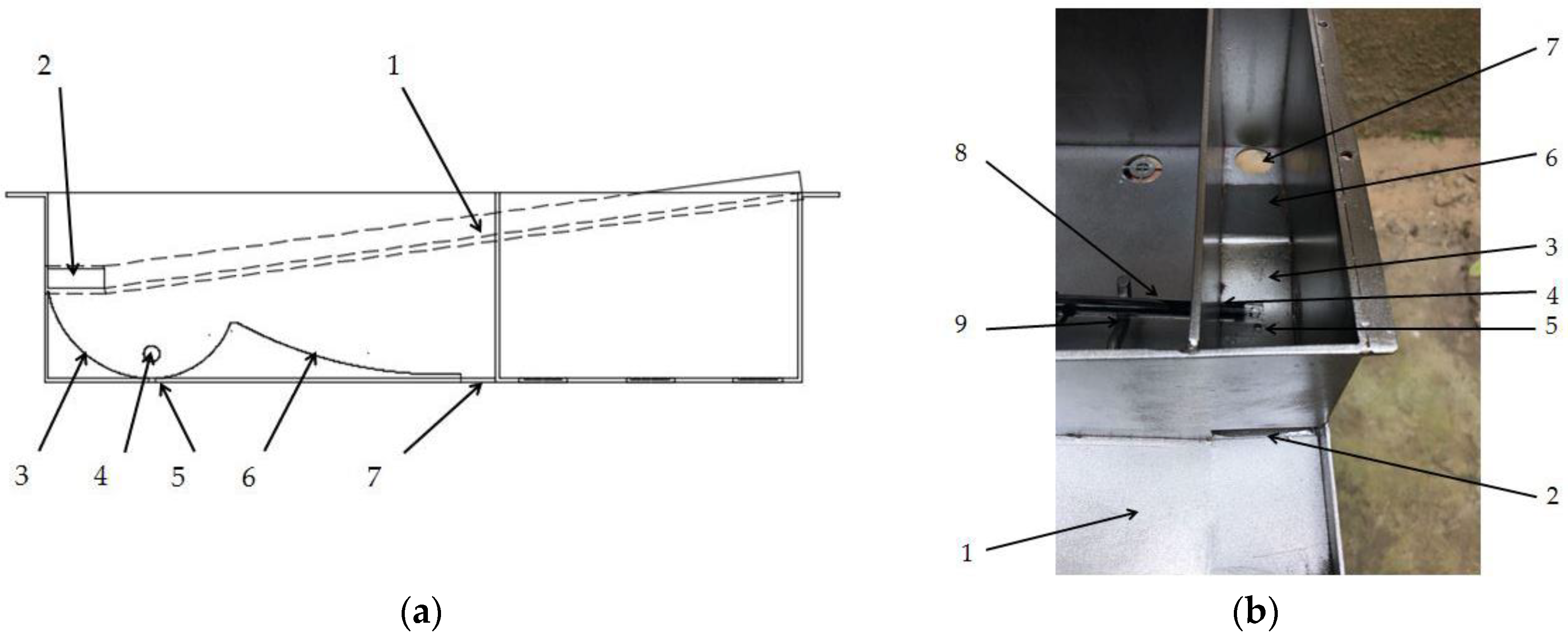
- The package device needs to realize the functions of collecting and exporting rainwater in order to achieve the measurement of the pH of the rainwater.
- Non-interfering installation for large sensors. Large sensors such as wind speed sensors and wind direction sensors need to be properly installed in a limited space.
- The installation of a solar self-powered system. As the outdoor nodes may be in an unattended environment for a long time, it is necessary to ensure the continuous supply of electricity in order to enable them to work uninterruptedly.
2.4. Software Design
3. Results
3.1. Packaging Structure
3.1.1. Indoor Node Package Box
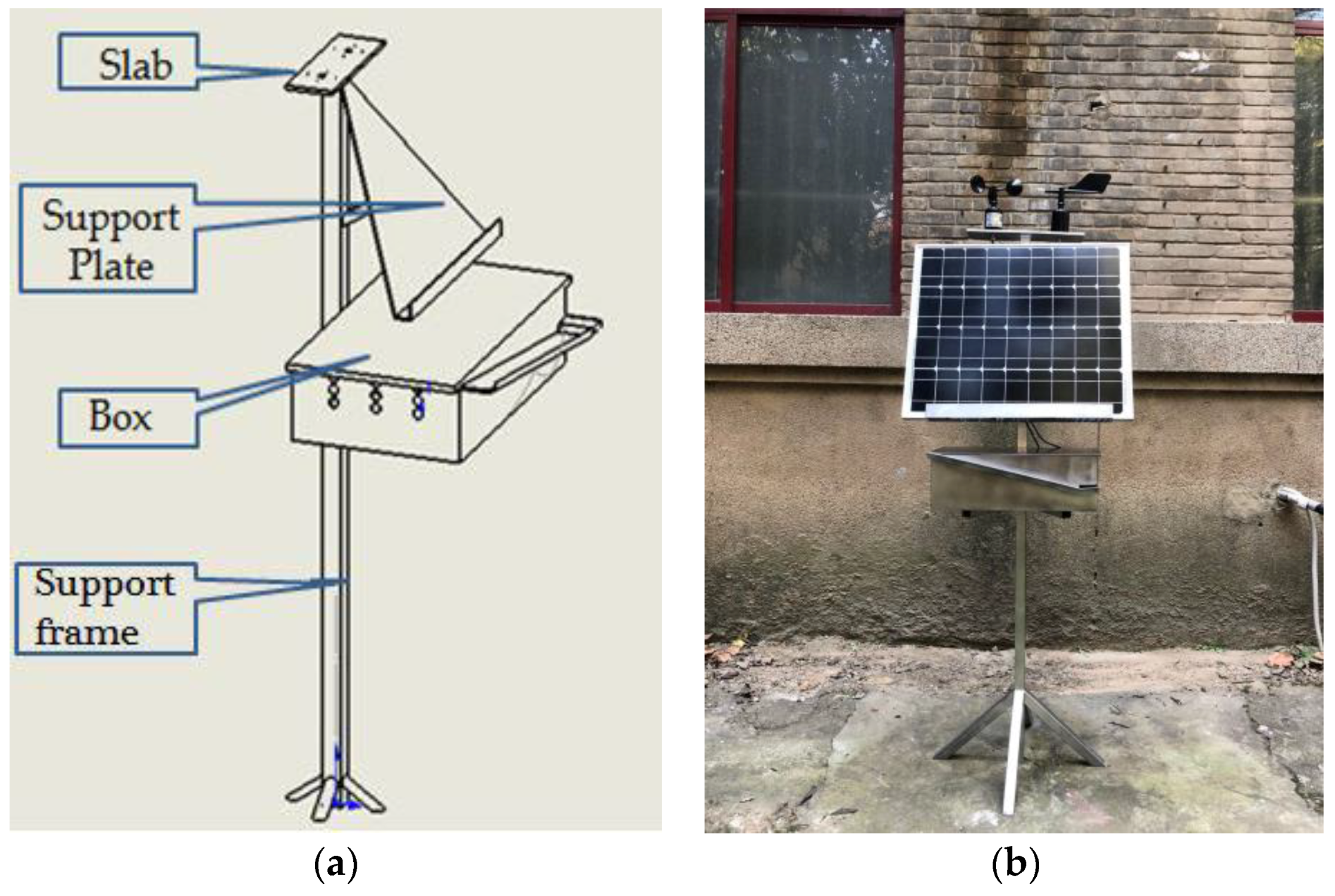
3.1.2. Outdoor Package Device
- Slab: place the wind speed sensor and the wind direction sensor.
- Support plate: place the solar photovoltaic panels.
- Box: lace the node modules and achieve the collection and automatic drainage of the rainwater.
- Support frame: mainly support the entire device.
3.2. Monitoring System
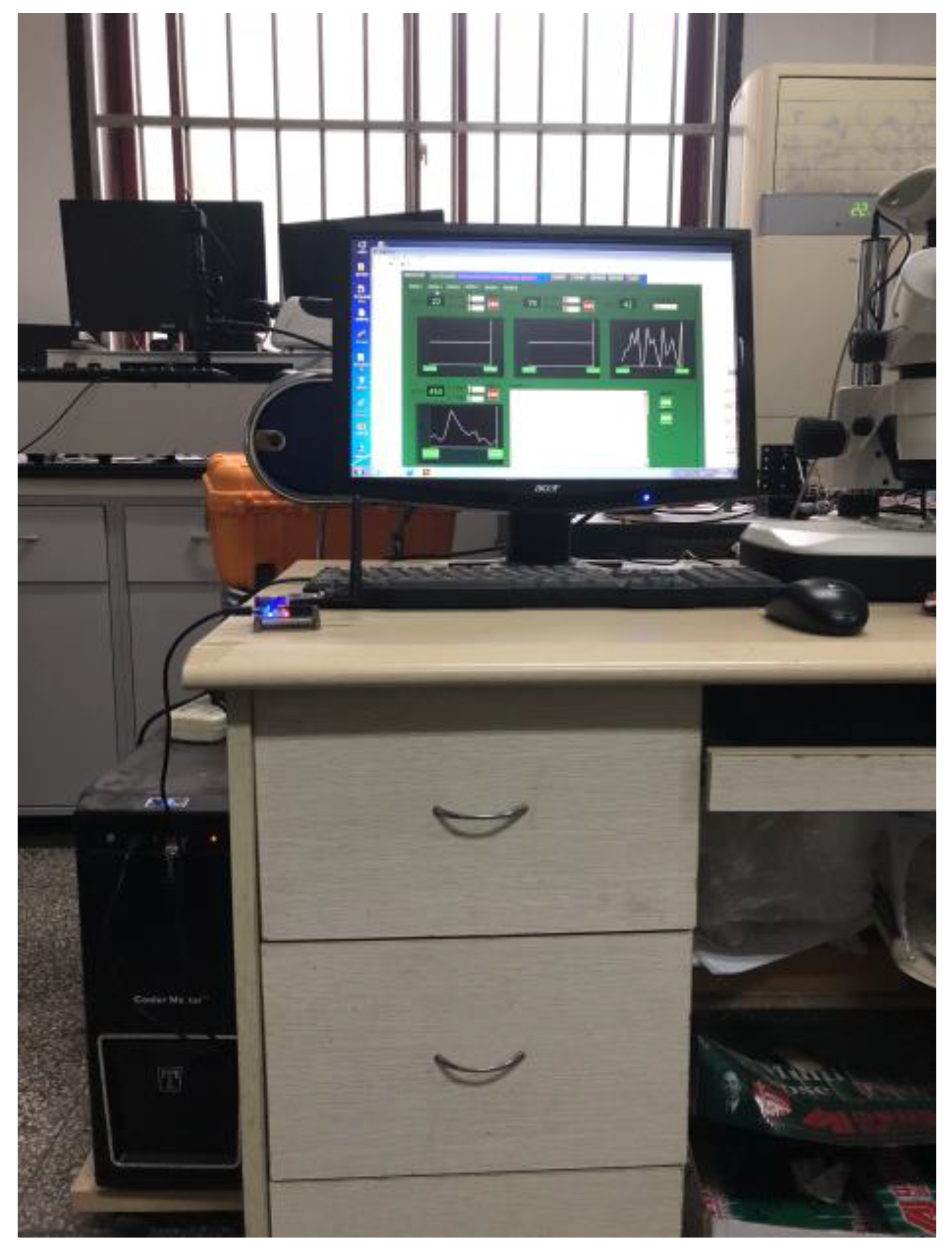
3.2.1. Monitoring Platform
3.2.2. Login System
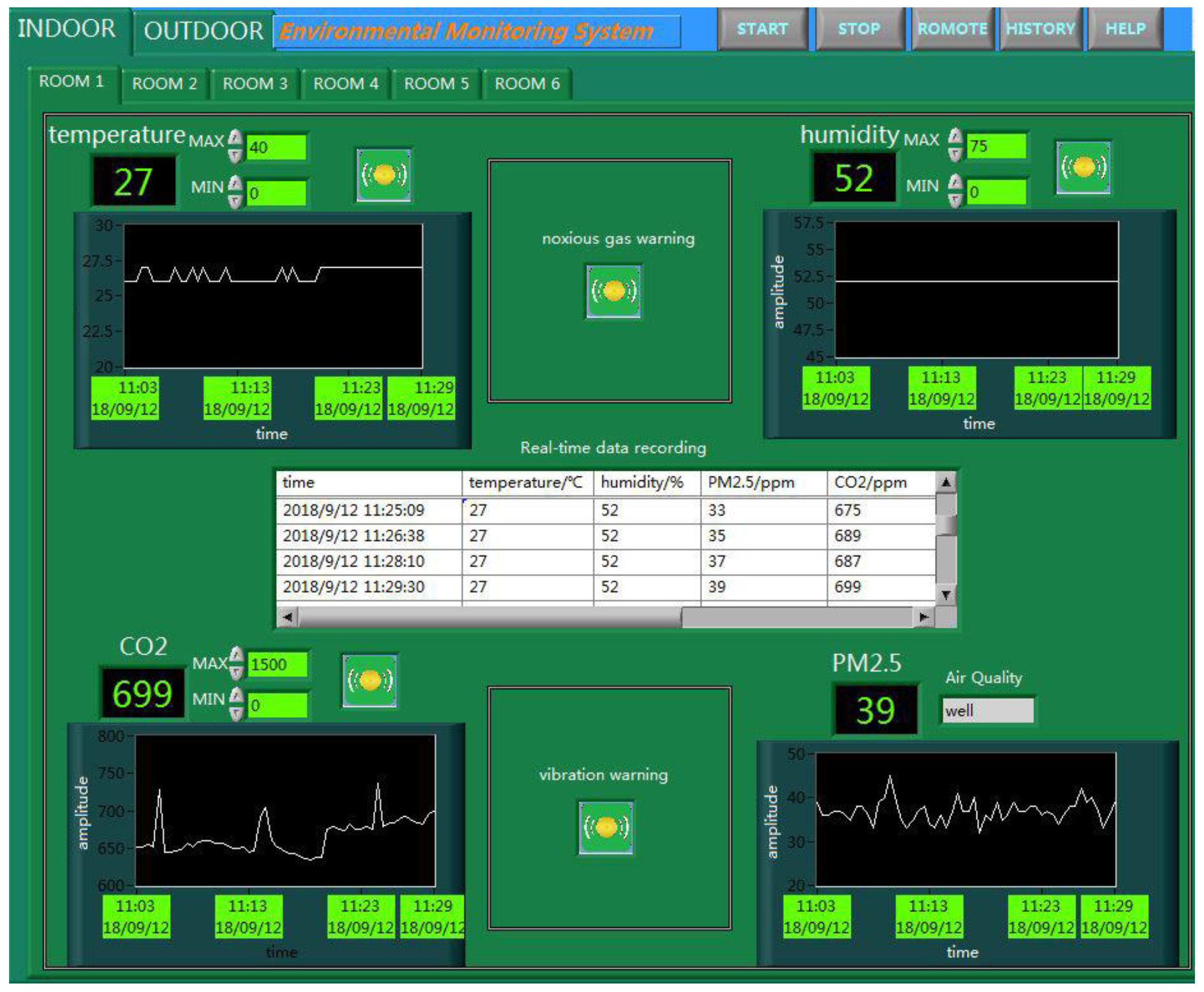
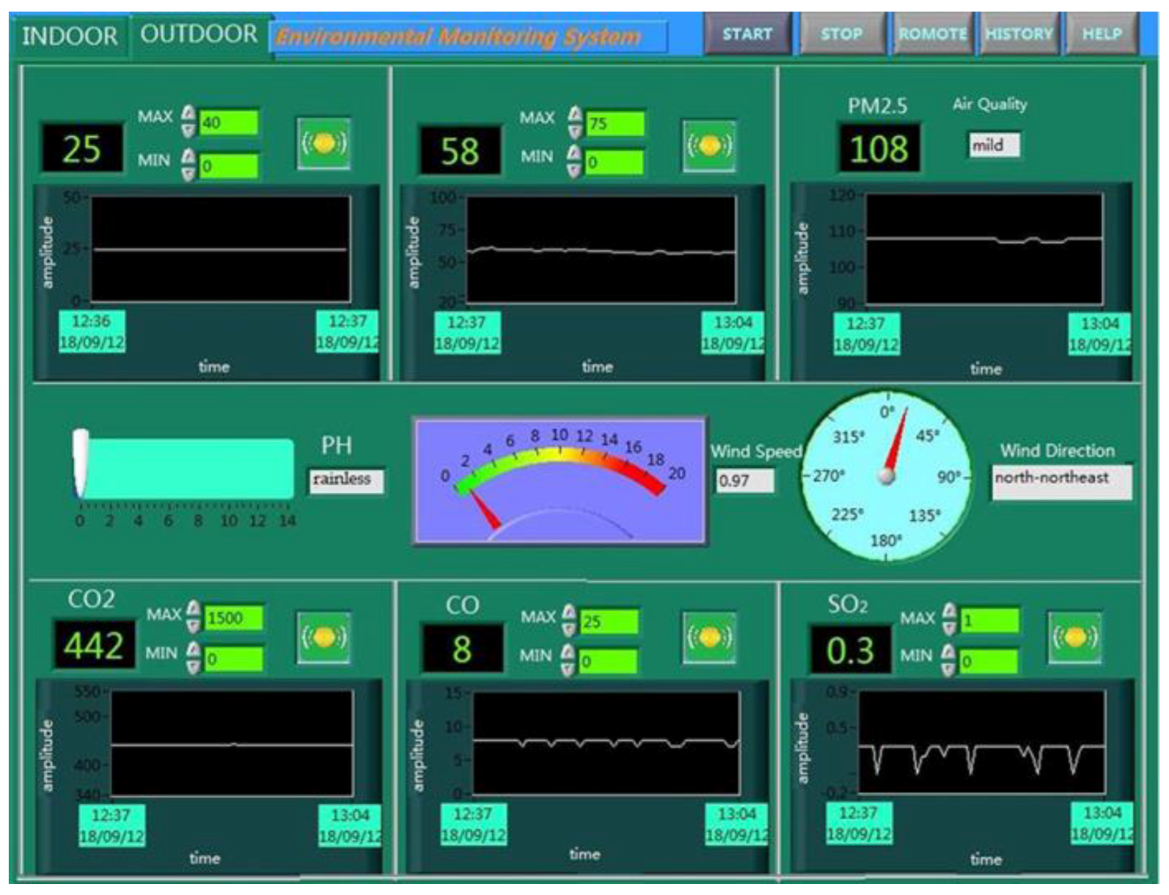
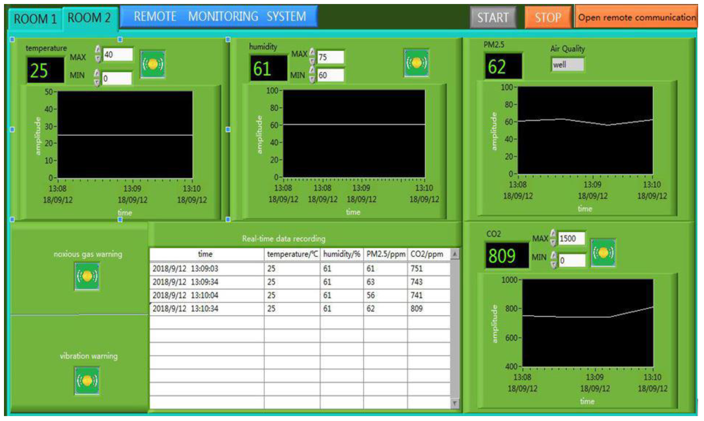
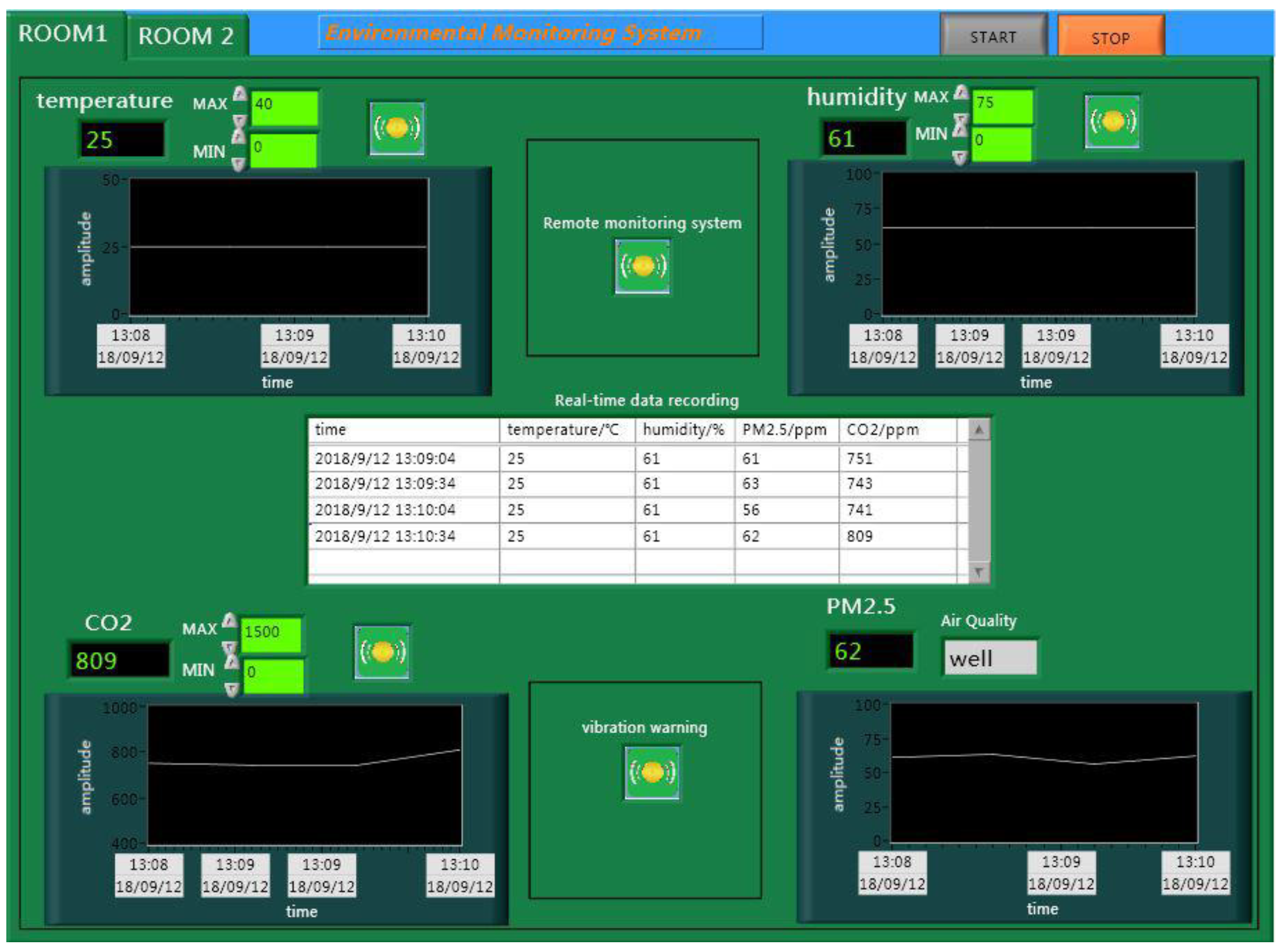
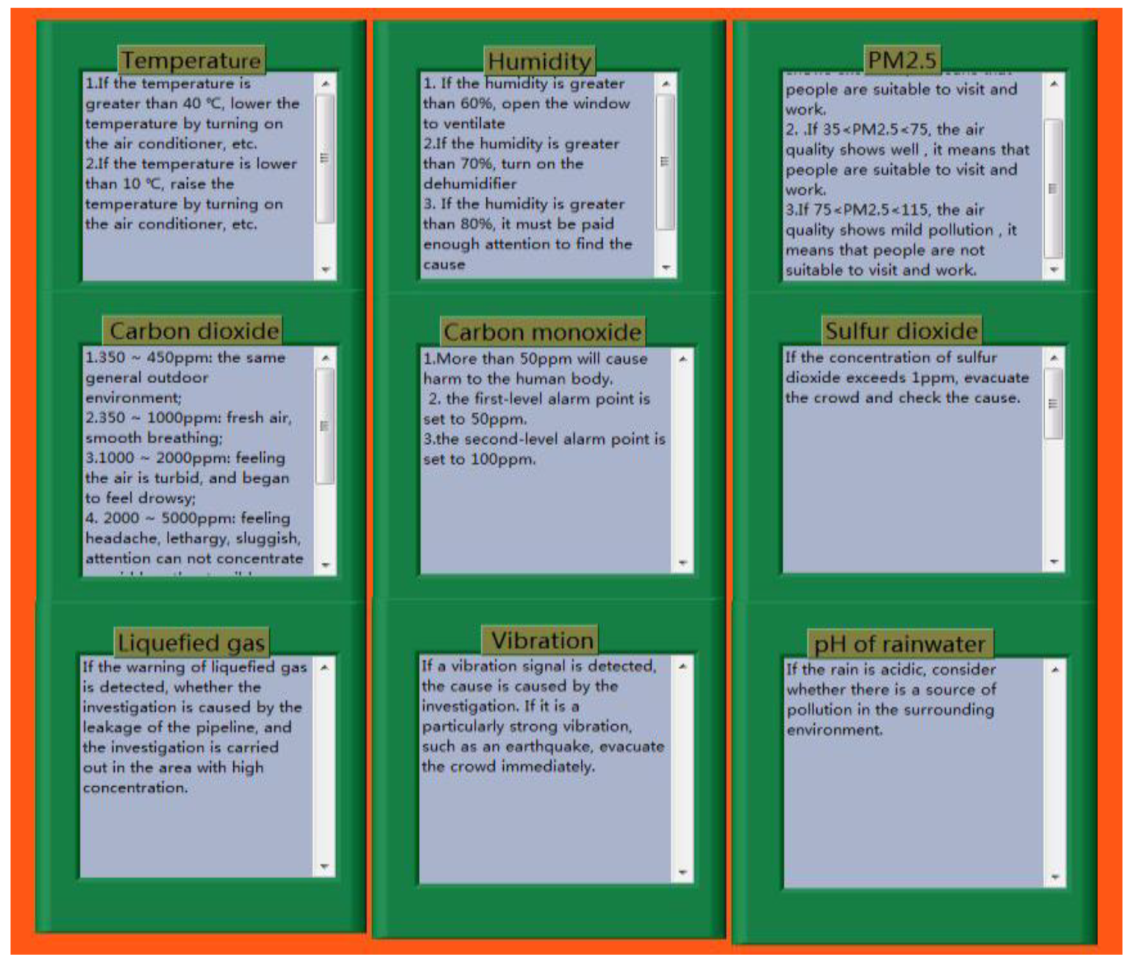
3.2.3. Main System
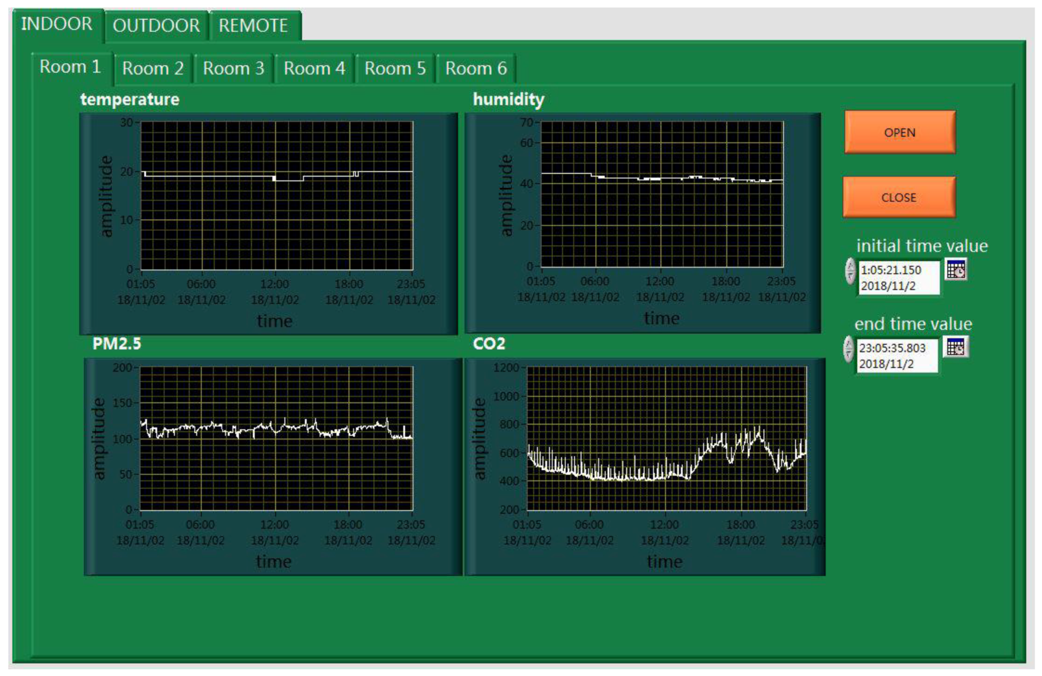
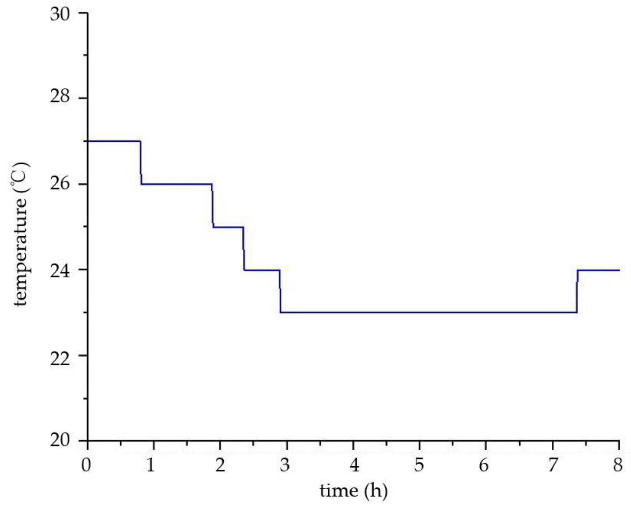
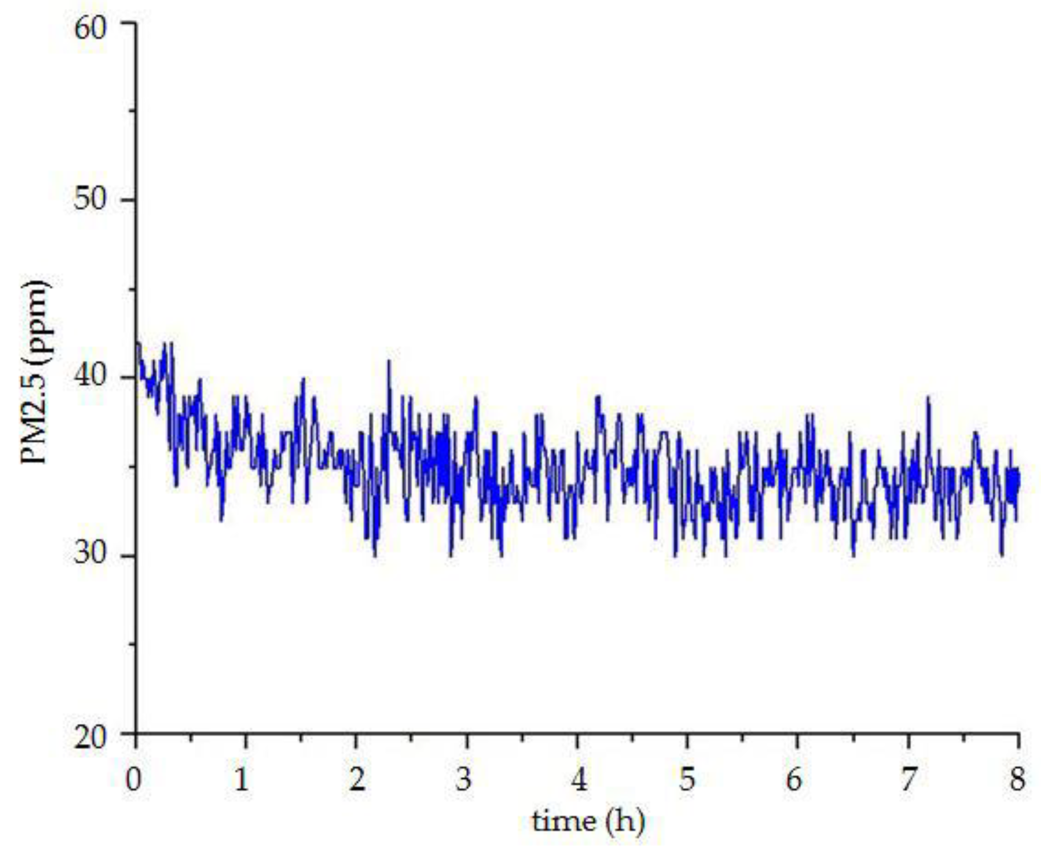
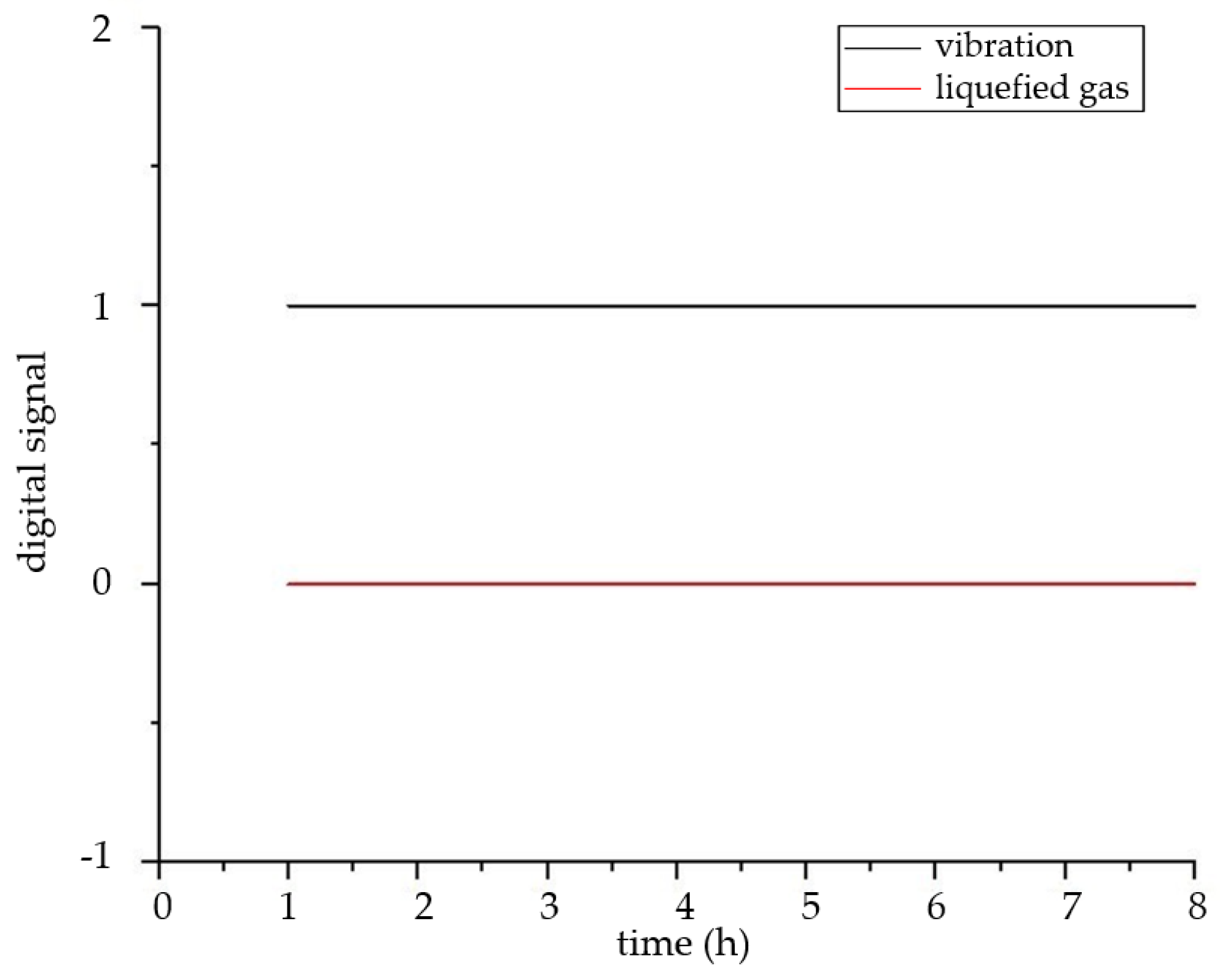
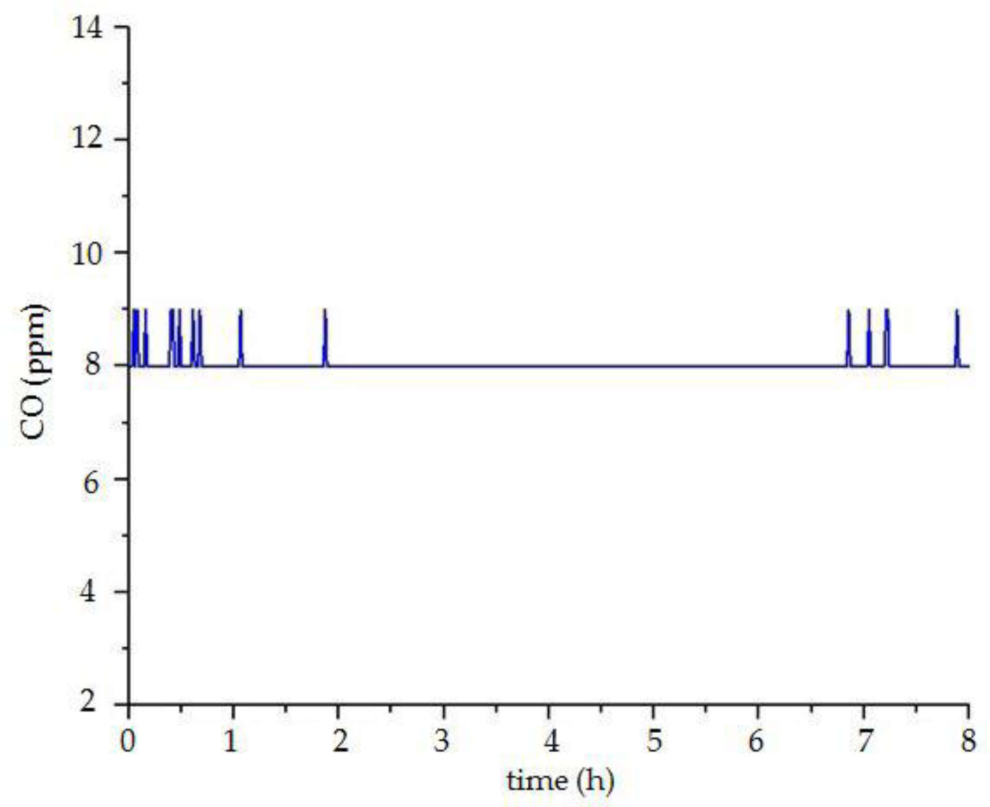
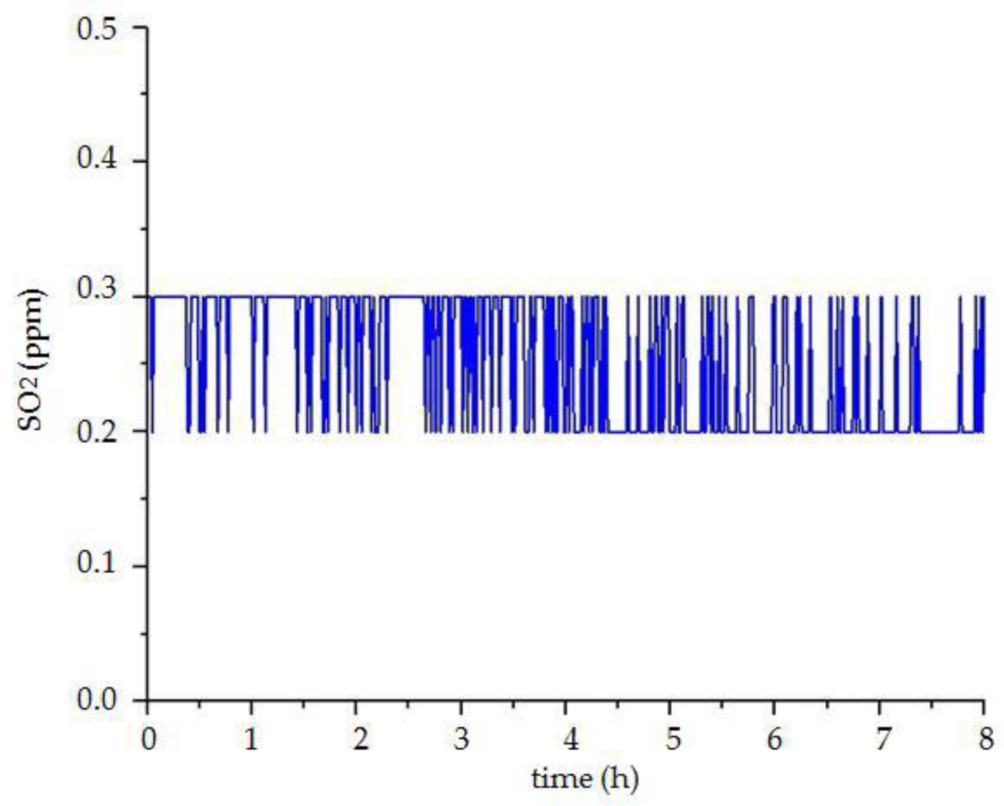
3.3. Data Analysis
4. Discussion
5. Conclusions
Author Contributions
Funding
Acknowledgments
Conflicts of Interest
References
- Wan, R.; Kong, D.Q.; Zhang, L.X. Study on Bottom Damp-Proof Method of Cave Dwelling. Adv. Civ. Eng. 2018. [Google Scholar] [CrossRef]
- Cannizzaro, F.; Pantò, B.; Lepidi, M.; Caddemi, S.; Caliò, I. Multi-Directional Seismic Assessment of Historical Masonry Buildings by Means of Macro-Element Modelling: Application to a Building Damaged during the L’Aquila Earthquake (Italy). Buildings 2017, 7, 106. [Google Scholar] [CrossRef]
- Richards-Rissetto, H. An iterative 3D GIS analysis of the role of visibility in ancient Maya landscapes: A case study from Copan, Honduras. Digit. Scholarsh. Humanit. 2017, 32. [Google Scholar] [CrossRef]
- Sato, T. The Reconstruction Problems that became Clear from the Plans and Projects for Reconstruction of Tsunami Stricken Fishery Village Area. J. Rural Plan. Assoc. 2012, 31, 26–32. [Google Scholar] [CrossRef]
- Wu, M. Monitoring of Architectural Heritage under the Concept of Preventive Conservation. Huazhong Archit. 2011, 29, 169–171. [Google Scholar]
- Liu, R.Z.; Zhang, B.J.; Zhang, H.; Shi, M.F. Deterioration of Yungang Grottoes: Diagnosis and research. J. Cult. Herit. 2011, 12, 494–499. [Google Scholar] [CrossRef]
- Abruzzese, D.; Angelaccio, M.; Giuliano, R.; Miccoli, L.; Vari, A. Monitoring and vibration risk assessment in cultural heritage via Wireless Sensors Network. In Proceedings of the 2009 2nd Conference on Human System Interactions, Catania, Italy, 21–23 May 2009. [Google Scholar]
- Mazloumi, E.; Asce, M.S.; Currie, G.; Rose, G. Using GPS data to gain insight into public transport travel time variability. J. Transp. Eng. 2010, 136, 623–631. [Google Scholar] [CrossRef]
- Diogo, K.; Chiaramonte, M.S.; Alexandre, B. Wireless Network for Measurement of Whole-Body Vibration. Sensors 2008, 8, 3067–3081. [Google Scholar]
- Ahmad, F.; Khan, I.; Mahmud, A.S.; Khan, M.G.; Yousaf, Z.F. Real time evaluation of shortest remaining processing time based schedulers for traffic congestion control using wireless sensor networks. In Proceedings of the IEEE International Conference on Connected Vehicles and Expo (ICCVE), Las Vegas, NV, USA, 2–6 December 2013; pp. 381–387. [Google Scholar]
- Kapileswar, N.; Hancke, G.P. A Survey on Urban Traffic Management System Using Wireless Sensor Networks. Sensors 2016, 16, 157. [Google Scholar]
- Bai, X.; Wang, Z.; Zou, L.; Cheng, C. Target Tracking for Wireless Localization Systems with Degraded Measurements and Quantization Effects. IEEE Trans. Ind. Electron. 2018, 65, 9687–9697. [Google Scholar] [CrossRef]
- Ruizgarcia, L.; Barreiro, P.; Robla, J.I.; Lunadei, L. Testing ZigBee motes for monitoring refrigerated vegetable transportation under real conditions. Sensors 2010, 10, 4968–4982. [Google Scholar] [CrossRef] [PubMed]
- Jiang, J.-A.; Liao, M.-S.; Lin, T.-S.; Huang, C.-K.; Chou, C.-Y.; Yeh, S.-H.; Lin, T.-T.; Fang, W. Toward a higher yield: A wireless sensor network-based temperature monitoring and fan-circulating system for precision cultivation in plant factories. Precis. Agric. 2018, 19, 929–956. [Google Scholar] [CrossRef]
- Anitha Mary, X.; Rose, L.; Rajasekaran, K. Continuous and remote monitoring of ground water level measurement in a well. Int. J. Water 2018, 12, 356–369. [Google Scholar] [CrossRef]
- Shi, G.; He, Y.; Luo, Q.; Li, B.; Zhang, C. Portable device for acetone detection based on cataluminescence sensor utilizing wireless communication technique. Sens. Actuators B Chem. 2018, 257, 451–459. [Google Scholar] [CrossRef]
- Hu, J. Application of ZigBee wireless sensor network in gas monitoring system. Acta Tech. CSAV 2017, 62, 255–264. [Google Scholar]
- Clarke, M.; Folter, J.D.; Verma, V.; Gokalp, H. Interoperable End-to-End Remote Patient Monitoring Platform based on IEEE 11073 PHD and ZigBee Health Care Profile. IEEE Trans. Biomed. Eng. 2017, 65, 1014–1025. [Google Scholar] [CrossRef]
- Leccese, F.; Cagnetti, M.; Trinca, D. A smart city application: A fully controlled street lighting isle based on Raspberry-Pi card, a ZigBee sensor network and WiMAX. Sensors 2014, 14, 24408–24424. [Google Scholar] [CrossRef]
- Wu, Q.; Cao, J.; Zhou, C.; Huang, J.; Li, Z.; Cheng, S.M.; Cheng, J.; Pan, G. Intelligent Smoke Alarm System with Wireless Sensor Network Using ZigBee. Wirel. Commun. Mob. Comput. 2018, 2018, 8235127. [Google Scholar] [CrossRef]
- Leccese, F. Remote-control system of high efficiency and intelligent street lighting using a zig bee network of devices and sensors. IEEE Trans. Power Deliv. 2013, 28, 21–28. [Google Scholar] [CrossRef]
- Chen, B.; Li, S.; Xu, N. Designing Wireless Monitoring System of Mountain Agriculture Based on ZigBee. Hubei Agric. Sci. 2015, 54, 457–460. [Google Scholar]
- P’erez-Garrido, C.; Gonz’alez-Castano, F.J.; Chaves-Diéguez, D.; Rodríguez-Hernández, P.S. Wireless remote monitoring of toxic gases in shipbuilding. Sensors 2014, 14, 2981–3000. [Google Scholar] [CrossRef] [PubMed]
- Gong, Q.; Li, G.; Pang, Y. Design and Implementation of Smart Home System Based on ZigBee Technology. Int. J. Smart Home 2014, 8, 143–156. [Google Scholar] [CrossRef]
- Huang, J.; Liu, H.R. Design of Intelligent pH Analyzer Based on ZigBee. Control Instrum. Chem. Ind. 2011, 6, 8. [Google Scholar]
- D’Alvia, L.; Palermo, E.; Del Prete, Z. Validation and application of a novel solution for environmental monitoring: A three months study at “Minerva Medica” archaeological site in Rome. Measurement 2018, 129, 31–36. [Google Scholar] [CrossRef]
- García Diego, F.-J.; Esteban, B.; Merello, P. Design of a hybrid (wired/wireless) acquisition data system for monitoring of cultural heritage physical parameters in smart cities. Sensors 2015, 15, 7246–7266. [Google Scholar] [CrossRef] [PubMed]
- Federici, F.; Alesii, R.; Colarieti, A.; Faccio, M.; Graziosi, F.; Gattulli, V. Analysis and Implementation of Distributed Data Processing in a Wireless Sensor Network for Structural Health Monitoring. Lect. Notes Electr. Eng. 2015, 319, 315–319. [Google Scholar]
- MartínezGarrido, M.I.; Fort González, R. Experimental assessment of a wireless communications platform for the built and natural heritage. Measurement 2016, 82, 188–201. [Google Scholar] [CrossRef]
- D’Alvia, L.; Palermo, E.; Rossi, S.; Cappa, P. Development of wireless sensor network for museum environmental monitoring. In Proceedings of the IMEKO International Conference on Metrology for Archeology and Cultural Heritage, Torino, Italy, 19–21 October 2016; pp. 100–105. [Google Scholar]
- Xie, Z.; Huang, G.; Zarei, R.; He, J.; Zhang, Y.; Ye, H. Wireless Sensor Networks for Heritage Object Deformation Detection and Tracking Algorithm. Sensors 2014, 14, 20562–20588. [Google Scholar] [CrossRef]
- Leccese, F.; Cagnetti, M.; Calogero, A.; Trinca, D.; Pasquale, S.D.; Giarnetti, S.; Cozzella, L. A New Acquisition and Imaging System for Environmental Measurements: An Experience on the Italian Cultural Heritage. Sensors 2014, 14, 9290–9312. [Google Scholar] [CrossRef]
- Mesas-Carrascosa, F.J.; Verdú Santano, D.; de Larriva, J.E.M.; Ortíz Cordero, R.; Hidalgo Fernández, R.E.; García-Ferrer, A. Monitoring heritage buildings with open source hardware sensors: A case study of the mosque-cathedral of Córdoba. Sensors 2016, 16, 1620. [Google Scholar] [CrossRef]
- Zhang, C.T.; Wang, L.K.; Hou, Y.N.; Guo, J. Micro environment control system of Mogao Grottoes in Dunhuang. J. Mech. Electr. Eng. 2015, 32, 571–574. [Google Scholar]
- Aparicio, S.; Martínezgarrido, M.; Ranz, J.; Fort, R.; Izquierdo, M.Á.G. Routing Topologies of Wireless Sensor Networks for Health Monitoring of a Cultural Heritage Site. Sensors 2016, 16, 1732. [Google Scholar] [CrossRef] [PubMed]
- Leccese, F.; Cagnetti, M.; Tuti, S.; Gabriele, P.; De Francesco, E.; Ðurović-Pejčev, R.; Pecora, A. Modified LEACH for Necropolis Scenario. In Proceedings of the IMEKO International Conference on Metrology for Archaeology and Cultural Heritage, Lecce, Italy, 23–25 October 2017. [Google Scholar]
- Agbota, H.; Mitchell, J.E.; Odlyha, M.; Strlič, M. Remote assessment of cultural heritage environments with wireless sensor array networks. Sensors 2014, 14, 8779–8793. [Google Scholar] [CrossRef] [PubMed]
- Zhao, Y.; Wang, Y.; Liu, Y.; Cheng, F. Ancient building electrical fire early warning system based on JenNet wireless technology. In Proceedings of the 2016 Chinese Control and Decision Conference (CCDC), Yinchuan, China, 28–30 May 2016. [Google Scholar]
- Zhang, Y.; Yang, J.; Wu, G.; Dong, Y. Design of Pulse Measuring Instrument Based on CC2530 Wireless Microcontroller. Jilin Norm. Univ. J. 2013, 4, 42. [Google Scholar]
- Qin, H.; Zhang, W. ZigBee-assisted power saving for more efficient and sustainable ad hoc networks. IEEE Trans. Wirel. Commun. 2013, 12, 6180–6193. [Google Scholar] [CrossRef]
- Bhattacharya, A.; Kumar, A. An Approximation to the QoS Aware throughput Region of a Tree Network under IEEE 802.15.4 CSMA/CA with Application to Wireless Sensor Network Design; Elsevier Science Publishers B.V.: Amsterdam, The Netherlands, 2015. [Google Scholar]
- Cagnetti, M.; Leccese, F.; Proietti, A. Energy saving project for heating system with ZigBee wireless control network. In Proceedings of the 2012 11th International Conference on Environment and Electrical Engineering (EEEIC 2012), Venice, Italy, 18–25 May 2012; pp. 580–585. [Google Scholar]
- Liu, Y. Energy saving and monitoring system for urban street lamps based on Zigbee wireless communication technology. J. Adv. Oxid. Technol. 2018, 21, 11875. [Google Scholar]


| Name of Sensor | Scope of Monitoring | Accuracy of Measurement | Type of Sensor |
|---|---|---|---|
| Relative humidity and temperature sensor | 0–50 °C | ±2 °C | DHT11 |
| 20–95% | ±5% | ||
| PM2.5 sensor | 0–8000 pcs | ±1 um | GP2Y1014AU0F |
| Carbon dioxide sensor | 0–2000 ppm | ±50 ppm | MH-Z19B |
| Carbon monoxide sensor | 0–500 ppm | ±1 ppm | AJD-4CO |
| Sulfur dioxide sensor | 0–20 ppm | ±0.1 ppm | AJD-4SO2 |
| liquefied gas sensor | 0/1 | MQ-2 | |
| Vibration sensor | 0/1 | SW-1801P | |
| Wind speed sensor | 0–70 m/s | ±0.3 m/s | YGC-FS |
| Wind direction sensor | 0–359° | ±3° | YGC-FX |
| pH sensor | 0–14 | ±0.01 | E-201-C |
| Connection between Indoor Terminal Device and Sensor | |
| Name of Sensor | Indoor Terminal Device |
| Relative humidity and Temperature sensor | P07, GND, 5 V |
| PM2.5 sensor | P06, P10, GND, 5 V |
| Carbon dioxide sensor | P04, GND, 5 V |
| Liquefied gas sensor | P05, GND, 5 V |
| Vibration sensor | P12, GND, 3.3 V |
| Connection between Outdoor Terminal Device 1 and Sensor | |
| Name of Sensor | Outdoor Terminal Device 1 |
| Relative humidity and temperature sensor | P07, GND, 5 V |
| PM2.5 sensor | P06, P10, GND, 5 V |
| Carbon dioxide sensor | P05, GND, 5 V |
| Carbon monoxide sensor | P04, GND, 3.3 V |
| Sulfur dioxide sensor | P00, GND, 3.3 V |
| Connection between Outdoor Terminal Device 2 and Sensor | |
| Name of Sensor | Outdoor Terminal Device 2 |
| Wind speed sensor | P04, GND, 5 V |
| Wind direction sensor | P06, GND, 5 V |
| pH sensor | P05, GND, 5 V |
| Monitoring System | Monitoring Parameter | Monitoring Software | Packaging Design |
|---|---|---|---|
| Wu et al. [20] | Smoke | Display and warning | No packaging design |
| Pérez-Garrido et al. [23] | Toxic gases | No design software | Simple |
| Zhang et al. [34] | Temperature, relative humidity, and carbon dioxide | Simple | Simple |
| Agbota et al. [37] | Alternative materials | Simple | Simple |
| Zhao et al. [38] | Electrical fire | No design software | Simple |
| This paper | Eleven parameters | Complete function | Two kinds of packaging |
| Scope of PM2.5 Concentration | Air Quality |
|---|---|
| 0 < PM2.5 ≤ 35 | Excellent |
| 35 < PM2.5 ≤ 75 | Well |
| 75 < PM2.5 ≤ 115 | Mild pollution |
| 115 < PM2.5 ≤ 150 | Moderate pollution |
| 150 < PM2.5 ≤ 250 | Severe contamination |
© 2018 by the authors. Licensee MDPI, Basel, Switzerland. This article is an open access article distributed under the terms and conditions of the Creative Commons Attribution (CC BY) license (http://creativecommons.org/licenses/by/4.0/).
Share and Cite
Lin, Q.; Zhang, F.; Jiang, W.; Wu, H. Environmental Monitoring of Ancient Buildings Based on a Wireless Sensor Network. Sensors 2018, 18, 4234. https://doi.org/10.3390/s18124234
Lin Q, Zhang F, Jiang W, Wu H. Environmental Monitoring of Ancient Buildings Based on a Wireless Sensor Network. Sensors. 2018; 18(12):4234. https://doi.org/10.3390/s18124234
Chicago/Turabian StyleLin, Qijing, Fuzheng Zhang, Weile Jiang, and Hao Wu. 2018. "Environmental Monitoring of Ancient Buildings Based on a Wireless Sensor Network" Sensors 18, no. 12: 4234. https://doi.org/10.3390/s18124234
APA StyleLin, Q., Zhang, F., Jiang, W., & Wu, H. (2018). Environmental Monitoring of Ancient Buildings Based on a Wireless Sensor Network. Sensors, 18(12), 4234. https://doi.org/10.3390/s18124234