Article

Space-Based Focal Plane Ambiguous Measurement Ballistic Target MeMber Tracking

Air and Missile Defense College, Air Force Engineering University, Xi’an 710051, China
*
Author to whom correspondence should be addressed.
Sensors 2018, 18(11), 3996; https://doi.org/10.3390/s18113996
Submission received: 21 October 2018 / Revised: 10 November 2018 / Accepted: 14 November 2018 / Published: 16 November 2018
(This article belongs to the Special Issue Satellite and Airborne Remote Sensing for Earth Monitoring)

Abstract

:
Aimed at space-based passive detection and tracking of ballistic targets, a multi-target multi-Bernoulli (MeMber) filtering algorithm based on a focal plane ambiguous measurement model is proposed. The measurement error sources of space-based passive detection are analyzed. It is found that focal plane target tracking is the basis of space target tracking in the framework of the distributed data processing structure, and the main error of focal plane measurement is pixel resolution. Based on the above analysis, the focal plane ambiguous measurement model is established to replace the traditional measurement model and the generalized likelihood function is designed. Finally, the MeMber filter is modified based on ambiguous measurement and generalized likelihood function. The simulation experiment compares the tracking effect of a MeMber filter based on ambiguous measurement and traditional measurement, respectively. The filter based on ambiguous measurement achieves better results. It shows that ambiguous measurement is closer to reality and has more application value.

1. Introduction

The space-based infrared detection system is becoming the best way to solve the problem of ballistic target early warning with the development of thermal imaging and tracking technology [1,2,3,4]. It can track all the targets concerned and provide effective information support for defense systems, strategic counterattack, fire control and effect evaluation. Detection information is usually processed in a distributed structure. A single platform infrared sensor detects and tracks the target in its own field of view. The tracking results are output to the fusion node for stereo fusion tracking and then the target trajectory is obtained [5,6]. Therefore, two-dimensional focal plane tracking of the target image is the most important part and also the key to detection information processing.
Unlike ordinary video target tracking, space-based infrared detectors are aimed at ballistic targets. Ballistic targets are small targets in space-based high-orbit detection scenarios. In the background of high-orbit space-based detectors, the imaging size of long-range targets and their plume on the focal plane is no more than one pixel. This is the difficulty of target tracking in space-based infrared detection system.
References [6,7,8] have studied two-dimensional focal plane target tracking, and established the target motion model and the sensor measurement model; the probability hypothesis density filter was introduced to deal with the multi-target tracking problem in a clutter environment, and the multi-sensor data fusion problem was studied. In this paper, the measurement model of the sensor is reconstructed. Considering that the measurement is inaccurate and cannot be described using random noise, it should be modeled as an UGA (unambiguously generated ambiguous measurement) [9]. Different from the traditional measurement method, the ambiguous measurement is not a specific value containing random noise, but the approximate area where the target is located. In space-based focal plane measurement, the pixel where the target is located is obtained using ambiguous measurement, but it is not sure where the target is located in the pixel.
In space-based infrared detection scenarios, clutters on the focal plane composed of clouds, atmosphere, aerial vehicles, and other radiation sources will interfere with target tracking. To solve this problem, many filtering algorithms are proposed, such as the single hypothesis correlation (SHC), multiple hypothesis correlation (MHC), and compound hypothesis correlation (CHC), represented by joint probabilistic data correlation (JPDA) [10,11]. In the case of a large number of clutters, it is difficult to achieve target tracking with traditional filtering algorithms, but the multi-target Bayesian recursive filter constructed by Mahler can effectively solve the tracking problem in such scenarios. The implementation methods of multi-target Bayesian recursive filters include the probability hypothesis density filter (PHD) [12,13], the cardinalized probability hypothesis density filter (CPHD) [14,15], and the multi-target multi-Bernoulli filter (MeMBer) [16,17,18]. The execution methods include Gaussian mixture approximation (GM) [19,20,21] and Sequential Monte Carlo (SMC) [22,23,24,25,26,27,28,29]. In addition, Vo’s Cardinality Balanced MeMBer Filter (CBMeMBer) [30,31] corrects the potential estimation bias of the MeMBer filter. CBMeMBer does not require clustering and the computational complexity is less than CPHD, so this paper uses the CBMeMBer filter to track the space-based focal plane boost trajectory target.
In the first section, the measurement error of the space-based infrared detector is analyzed, the focal plane measurement is modeled, and the generalized likelihood function is given; in the second section, the reconstruction algorithm of the MeMBer filter is given based on the UGA measurement; and in the third section, the simulation results are compared to verify the effectiveness of the proposed method.

2. Detection Error Analysis and Focal Plane Measurement Modeling

Three main types of errors exist in space-based infrared detection: time error, LOS (line of sight) error, and satellite position error [32]. The amplitude of the time error is relatively small, and it can be gradually smaller with continuous measurement. The LOS error is mainly caused by the instability of satellite attitude and the measurement error of infrared radiation. In addition, the measurement error can also be caused by the detector noise, infrared refraction, and attenuation. The ephemeris of the satellite is not real-time, thus the position of the satellite is not accurate.
According to the distributed information processing system of the space-based optical detection system, the measurement object of the detector focal plane is the target image, the error source is the infrared radiation measurement error, and the position of the image on the two-dimensional focal plane is obtained; the fusion node inverts the position of the image on each two-dimensional focal plane into the position of the target in three-dimensional space. The error sources are the position, attitude, direction, and time errors of the sensors, and the trajectory of the target in three-dimensional space is obtained. Therefore, only the errors caused by infrared radiation measurement need to be considered in focal plane target tracking, which is mainly determined by the pixel resolution of the focal plane.
The relationship between the plane coordinate system and the sensor coordinate system is shown in Figure 1:
where O f u v is the focal plane coordinate system, O s U E N is the sensor coordinate system, and f is the focal length.
For point targets, the error of infrared radiation measurement is mainly due to pixel resolution. As shown in Figure 2, in space-based infrared detection, when the target is too far away from the detector, its image occupies less than one pixel on the focal plane. By measuring the coordinates of the pixels, the position of the image cannot be given more accurately. The data we can obtain is which pixel the target is in. Therefore, it is unwise to use the center of the pixel as the target image position.
In traditional methods, observations are often modeled as noisy random variables.
{ u = x + v x v = y + v y
where v x and v y are zero mean Gaussian white noise N ( 0 , σ 2 ) and the set of standard deviation σ needs to consider pixel resolution.
In fact, measurements should be modeled as follows:
The measurement is denoted by ( u , v ) , the target position is denoted by ( x , y ) , and the measurement equation is:
{ u = [ x / c , x / c ] v = [ y / c , y / c ]
In Equation (1), u and v are scalar; in Equation (2), u and v are interval variables represented by using upper and lower bounds, ‘⌊⌋’ is ‘Floor’, ‘⌈⌉’ is ‘Ceiling’, and c is pixel size.

3. MeMber Filter Based on Ambiguous Measurement

3.1. Generalized Likelihood Function Based on Ambiguous Measurement

The definition of generalized likelihood function given in Reference [33] is:
f ( Θ | x ) Pr ( η ( x ) Θ )
In the process of focal plane measurement, Θ is the area where the pixel is on the focal plane, and x denotes the location of the target.
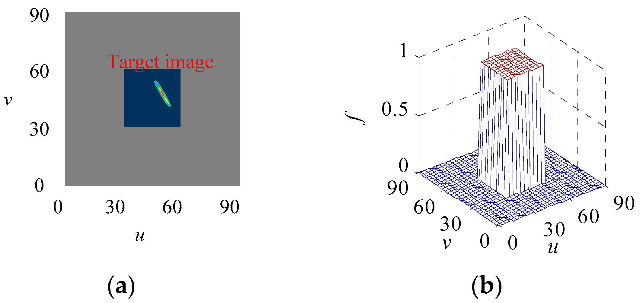
In other words, the generalized likelihood function is the probability of a target falling into a specified pixel region. As shown in Figure 3a, the target image is located in the dark area on the image plane. Due to the limitation of the pixel resolution, the accurate position of the target image cannot be obtained. Therefore, the likelihood probability density obeys a uniform distribution within the observation pixel region, and the probability density is 0 outside the observation area, as is shown in Figure 3b.

3.2. SMC-CBMeMber Filter Based on Ambiguous Measurement

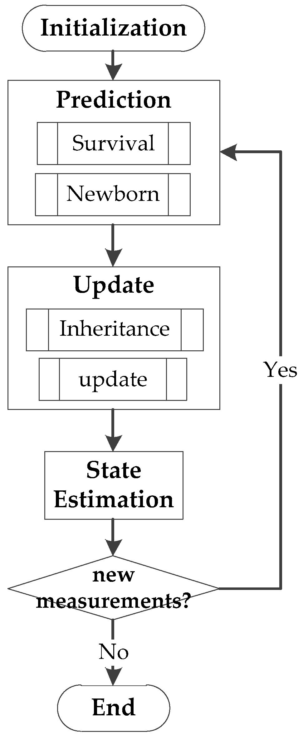
The steps of the CBMeMber filter can be shown in a block diagram, as in Figure 4:
The two most crucial steps are the prediction and the update.
(1) Prediction
In time step k − 1, the posterior multi-target density is a multi-Bernoulli of the form:
π k 1 = { ( r k 1 ( i ) , p k 1 ( i ) ) } i = 1 M k 1
The predicted multi-target density is also a multi-Bernoulli of the form:
π k | k 1 = { ( r P , k | k 1 ( i ) , p P , k | k 1 ( i ) ) } i = 1 M k 1 { ( r Γ , k ( i ) , p Γ , k ( i ) ) } i = 1 M Γ , k
where { ( r Γ , k ( i ) , p Γ , k ( i ) ) } i = 1 M Γ , k is the newborn MeMber density, { ( r P , k | k 1 ( i ) , p P , k | k 1 ( i ) ) } i = 1 M k 1 is the survival MeMber density, and
r P , k | k 1 ( i ) = r k 1 ( i ) p k 1 ( i ) , p S , k
p P , k | k 1 ( i ) ( x ) = f k | k 1 ( x | · ) , p k 1 ( i ) p S , k p k 1 ( i ) , p S , k
(2) Update
The predicted multi-target density in time step k is denoted by
π k | k 1 = { ( r k | k 1 ( i ) , p k | k 1 ( i ) ) } i = 1 M k | k 1
where M k | k 1 = M k 1 + M Γ , k ;
In time step k, posterior multi-target density is a multi-Bernoulli of the form:
π k { ( r L , k ( i ) , p L , k ( i ) ) } i = 1 M k | k 1 { ( r U , k ( i ) ( z ) , p U , k ( i ) ( x ; z ) ) } z Z k
where Z k is the measurement set in time step k, and { ( r L , k ( i ) , p L , k ( i ) ) } i = 1 M k | k 1 is the inheritance (missing) track MeMber density. If the detection probability is set to p D , k ( x ) , then
r L , k ( i ) = r k | k 1 ( i ) 1 p k | k 1 ( i ) , p D , k 1 r k | k 1 ( i ) p k | k 1 ( i ) , p D , k
p L , k ( i ) = p k | k 1 ( i ) ( x ) 1 p D , k ( x ) 1 p k | k 1 ( i ) , p D , k
{ ( r U , k ( i ) ( z ) , p U , k ( i ) ( x ; z ) ) } z Z k is the measurement updated MeMber density, and
r U , k ( i ) ( z ) = i = 1 M k | k 1 r k | k 1 ( i ) ( 1 r k | k 1 ( i ) ) p k | k 1 ( i ) , ψ k , z ( x ) ( 1 r k | k 1 ( i ) p k | k 1 ( i ) , p D , k ) 2 κ k ( z ) + i = 1 M k | k 1 r k | k 1 ( i ) p k | k 1 ( i ) , ψ k , z ( x ) 1 r k | k 1 ( i ) p k | k 1 ( i ) , p D , k
p U , k ( i ) ( x ; z ) = i = 1 M k | k 1 r k | k 1 ( i ) 1 r k | k 1 ( i ) p k | k 1 ( i ) ψ k , z ( x ) i = 1 M k | k 1 r k | k 1 ( i ) 1 r k | k 1 ( i ) p k | k 1 ( i ) , ψ k , z
ψ k , z ( x ) = g k ( z | x ) p D , k ( x )
The SMC-CBMeMber filter is the particle realization form of CBMeMber, since the measurement involves only the MeMber density update section, the SMC-CBMeMber update section is briefly described.
The multi-target density at time step k − 1 is shown in Equation (4). Each component can be approximated by weighted particles p k 1 ( i ) ( x ) = j = 1 L k 1 ( i ) w k 1 ( i , j ) δ x k 1 ( i , j ) ( x ) , where δ ( x ) is the Dirac function for the state x. The prediction of each component is p k | k 1 ( i ) ( x ) = j = 1 L k | k 1 ( i ) w k | k 1 ( i , j ) δ x k | k 1 ( i , j ) ( x ) .
The multi-target density of the inheritance (missing) part in the update step can be approximated to:
w L , k ( i , j ) = w L , k 1 ( i , j ) ( 1 p D , k ( x k | k 1 ( i , j ) ) ) j = 1 L k | k 1 ( i ) w k | k 1 ( i , j ) ( 1 p D ( x k | k 1 ( i , j ) ) )
The measurement updated multi-target density { ( r U , k ( i ) ( z ) , p U , k ( i ) ( x ; z ) ) } z Z k can be approximated to:
w U , k ( i , j ) ( z ) = w k | k 1 ( i , j ) r k | k 1 ( i ) 1 r k | k 1 ( i ) ψ k , z ( x k | k 1 ( i , j ) ) i = 1 M k | k 1 j = 1 L k | k 1 ( i ) w k | k 1 ( i , j ) r k | k 1 ( i ) 1 r k | k 1 ( i ) ψ k , z ( x k | k 1 ( i , j ) )
The probability of existence r L , k ( i ) and r U , k ( i ) ( z ) can be calculated by substituting p k | k 1 ( i ) ( x ) = j = 1 L k | k 1 ( i ) w k | k 1 ( i , j ) δ x k | k 1 ( i , j ) ( x ) into Equations (9) and (11).
ψ k , z ( x k | k 1 ( i , j ) ) = { 1 / c 2 , x k | k 1 ( i , j ) z 0 , x k | k 1 ( i , j ) z

4. Simulation Experiment

The following simulation experiments are designed to verify the effectiveness of the proposed ambiguous measurement MeMber filter in space-based infrared focal plane target tracking. To compare with the effect of the measurement modeling method based on Reference [2], the model of target motion is used.
(1) Motion modeling of boost-phase ballistic target
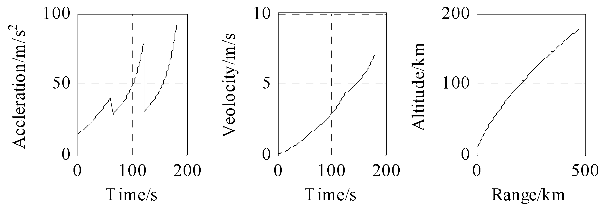
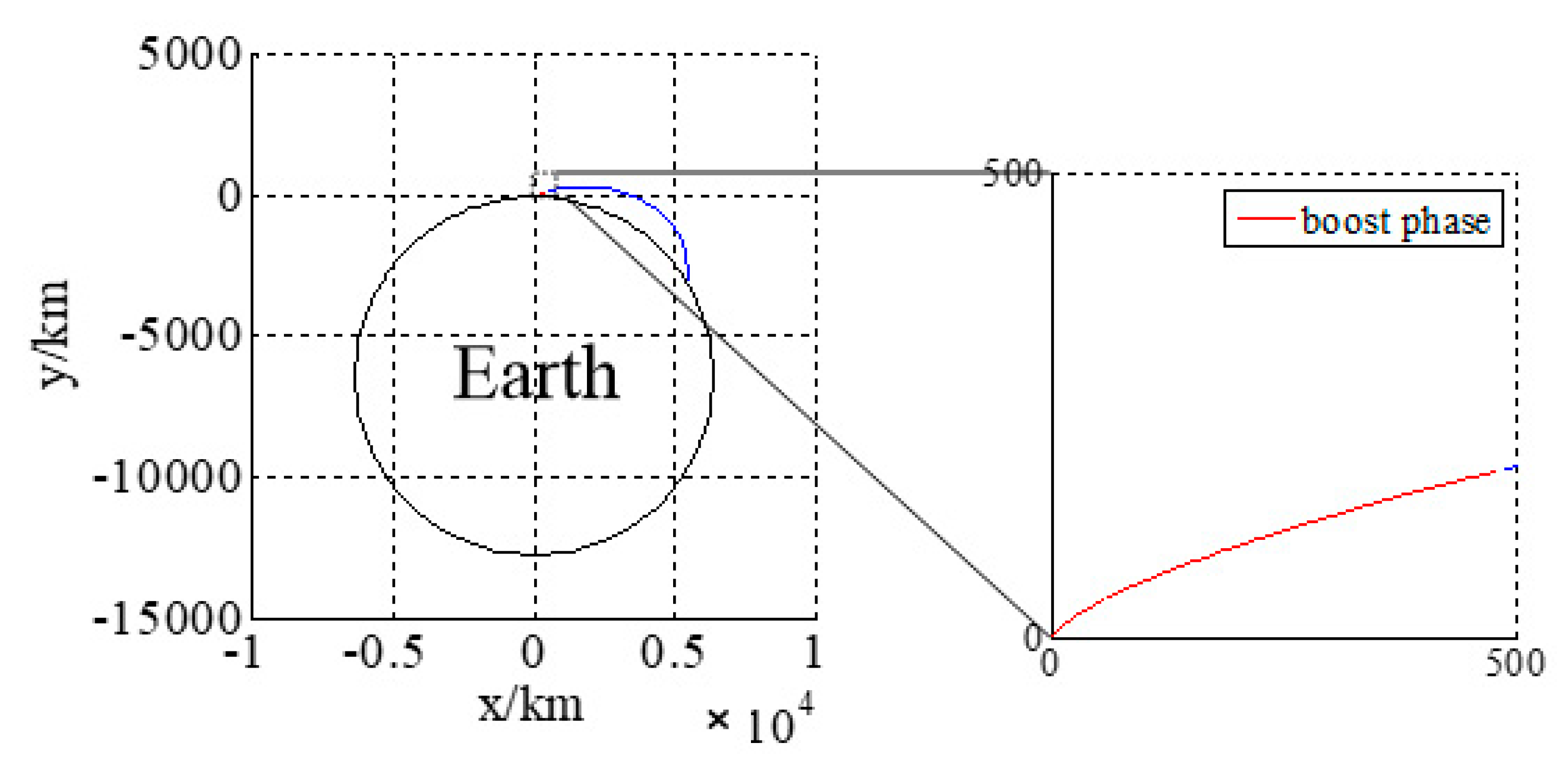
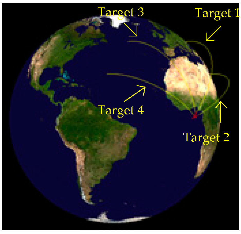
The acceleration, velocity, and trajectory of the three-stage rocket model are shown in Figure 5. The trajectory in launch the coordinate system is shown in Figure 6: the red part is the boost phase, and the blue part is the free-flight phase. The total time is 180 s.
(2) Launch and detector parameter
Let us suppose that the satellite carrying the detector is a geosynchronous orbit satellite with a sub-satellite position (N 0°, W 40°), the sensor is a staring detector, the frame time is 1 second, pointing to the center of the earth, the focal plane array is 1024 × 1024 pixels, the pixel size is 30 μm × 30 μm, the focal length is 1 m, and the instantaneous field of view is 0.0307 rad × 0.0307 rad.
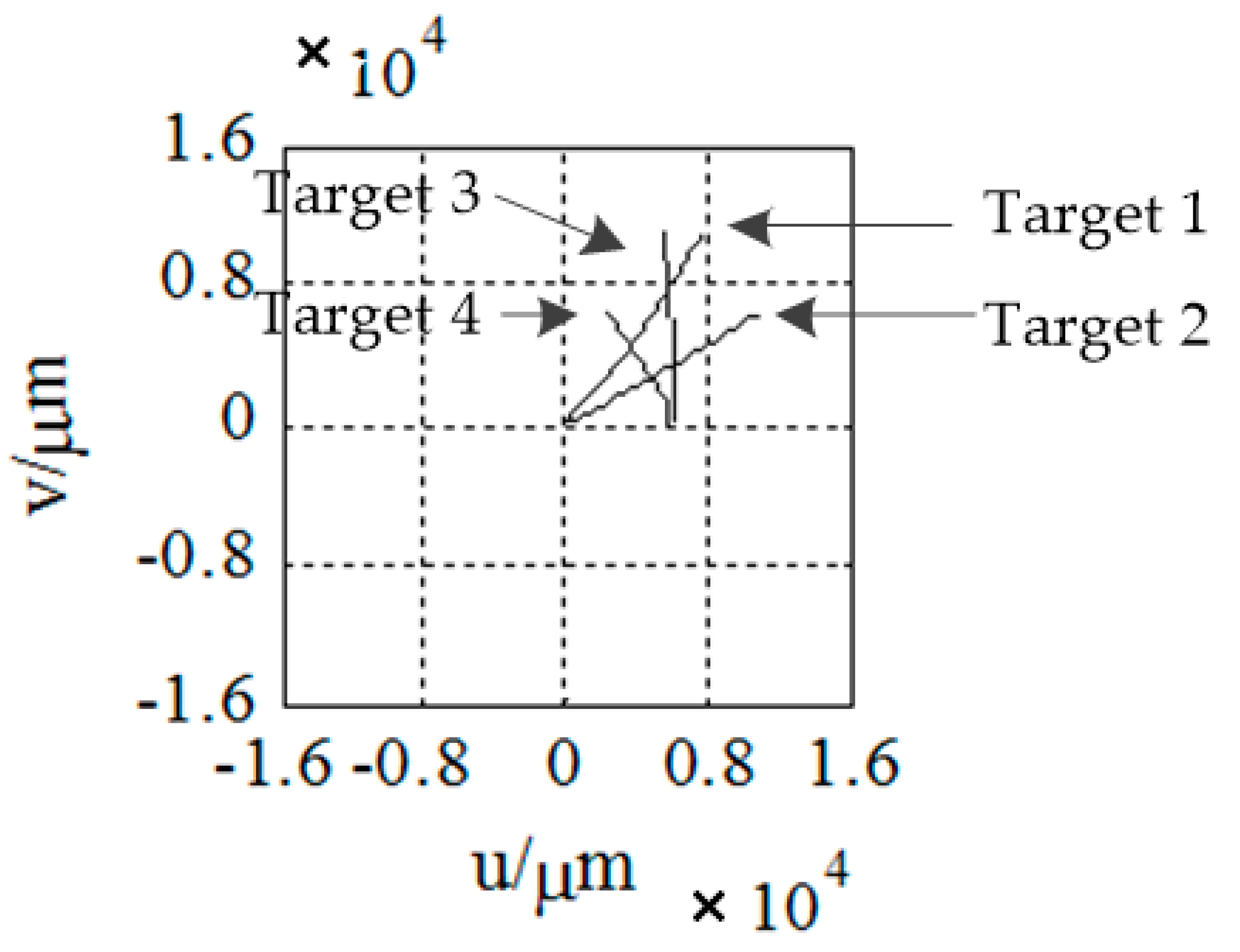
As is shown in Figure 7 and Figure 8, four targets appear in the field of view, in turn, and the target motion conforms to the motion model established above. Let us suppose that all the targets are captured by the detector after 30 seconds of launching. Let us take the time when target 1 is captured as the initial time. The launch point and shooting are shown in Table 1. We then continue to monitor the field of view until all the targets burn out and the traces of the targets on the focal plane are obtained, as shown in Figure 9.
We can assume that the number of clutters on the focal plane obeys a Poisson distribution with a parameter of 10, and all the 181 s measurements of the scene are shown in Figure 10. Figure 10a shows all the measurements in the whole field of view of the detector. To make the local details clearer, Figure 10b shows an enlargement of the dotted box in Figure 10a, and Figure 10c shows an enlargement of the dotted box in Figure 10b. The measurement is a rectangular region corresponding to the pixel, as can be seen clearly in Figure 10c.
(3) Filtering and tracking
The target tracking results obtained using the SMC-CBMeMber filter are as follows. The cardinality and optimal subpattern assignment (OSPA) are selected as evaluation indexes.
Figure 11 shows the trajectory tracking curves, estimated cardinality, and OSPA based on ambiguous measurement. Among them, Figure 11a is the trajectory tracking effect, where the red dot represents the real target trajectory, and the triangle represents the estimated target trajectory; Figure 11b is the estimated cardinality of 181 s; Figure 11c is the OSPA of 181 s. As can be seen from the Figure, the accurate target trajectory and target number can be obtained by filtering, and the OSPAs are all smaller than 20.
Figure 12 shows the trajectory tracking curves, estimated cardinality, and OSPA based on traditional measurement. As can be seen from the Figure, the SMC-CBMeMber filter based on traditional measurement has a relatively large trajectory tracking error, a slight deviation in cardinality estimation, and a relatively large OSPA.
In general, the SMC-CBMeMber filtering method based on ambiguous measurement achieves better results, with a more accurate trajectory tracking effect and a more accurate target number estimation.
The reason for this is that the measurement noise is modeled as a Gaussian distribution in traditional measurement; as such, the likelihood probability is distributed across the whole observation space, meaning that invalid observation will have some side effects on the target trajectory estimation. The likelihood probability of ambiguous measurement, on the other hand, is only distributed in part of the space where the observation pixel is located, meaning that the estimation of the target trajectory is not affected by the observation of the far away particles set.

5. Conclusions

In this paper, a multi-target tracking method for the space-based infrared focal plane in clutter condition is studied, and an ambiguous measurement model is established to model the measurement as an interval variable, which is more in line with the actual situation. Finally, the SMC-CBMeMber filtering algorithm based on ambiguous measurement shows better results in simulation. In the future, further research will be carried out in relation to three aspects: first, the detection environment and clutter density will be studied in depth to improve the reliability of the algorithm; second, interval analysis theory will be introduced to improve the tracking algorithms; and third, ground experiments and environmental simulation experiments will be gradually carried out.

Author Contributions

Conceptualization, Methodology and Validation, W.Z.; Supervision, S.H.; Formal Analysis and Resources, W.C.

Funding

This work was supported by National Natural Science Fund of China under grant no. 61703424.

Conflicts of Interest

The authors declare no conflict of interest.

References

  1. Glowacz, A.; Glowacz, Z. Diagnostics of stator faults of the single-phase induction motor using thermal images, MoASoS and selected classifiers. Measurement 2016, 93, 86–93. [Google Scholar] [CrossRef]
  2. Singh, G.; Naikan, V.N.A. Infrared thermography based diagnosis of inter-turn fault and cooling system failure in three phase induction motor. Infrared Phys. Technol. 2017, 87, 134–138. [Google Scholar] [CrossRef]
  3. Boone, N.; Zhu, C.; Smith, C.; Todd, I.; Willmott, J.R. Thermal near infrared monitoring system for electron beam melting with emissivity tracking. Addit. Manuf. 2018, 22, 601–605. [Google Scholar] [CrossRef]
  4. Johnson, B.; Thomas, S.; Rani, J.S. A novel framework for objective detection and tracking of TC center from noisy satellite imagery. Adv. Space Res. 2018, 62, 44–54. [Google Scholar] [CrossRef]
  5. Blackman, S.; Popoli, R. Design and Analysis of Modern Tracking Systems (Artech House Radar Library); Artech House: Norwood, MA, USA, 1999. [Google Scholar]
  6. Lin, L.K.; Xu, D.; Sheng, W.D.; An, W.; Xu, H. Spaceborne infrared image plane tracking method for midcourse ballistic target group based on random finite sets. J. Infrared Millim. Waves 2010, 6, 465–470. [Google Scholar]
  7. Lin, L.K.; Xu, H.; Long, Y.L.; An, W.; Xie, K. Infrared multisensor group tracking method for midcourse ballistic target group based on probability hypothesis density filtering. Acta Opt. Sin. 2011, 2, 262–269. [Google Scholar]
  8. Sheng, W.D.; Lin, L.K.; Zhou, Y.Y.; An, W. A performance analysis method of passive multisensor multitarget track association based on multiBernoulli model. Signal Process. 2010, 26, 1526–1531. [Google Scholar]
  9. Zhao, W.; Huang, S. Ballistic target PHD filter based on infrared focal plane ambiguous observation. Math. Prob. Eng. 2017. [Google Scholar] [CrossRef]
  10. Blackman, S.S. Multiple hypothesis tracking for multiple target tracking. IEEE Aerosp. Electron. Syst. Mag. 2004, 19, 5–18. [Google Scholar] [CrossRef]
  11. Svensson, L.; Svensson, D.; Guerriero, M.; Willett, P. Set JPDA filter for multitarget tracking. IEEE Trans. Signal Process. 2011, 59, 4677–4691. [Google Scholar] [CrossRef]
  12. Granstrom, K.; Orguner, U. A PHD filter for tracking multiple extended targets using random matrices. IEEE Trans. Signal Process. 2012, 60, 5657–5671. [Google Scholar] [CrossRef]
  13. Granström, K.; Willett, P.; Bar-Shalom, Y. PHD filter with approximate multiobject density measurement update. In Proceedings of the 18th International Conference on Information Fusion, Washington, DC, USA, 6–9 July 2015. [Google Scholar]
  14. Mahler, R.P.S.; Vo, B.T.; Vo, B.N. CPHD filtering with unknown clutter rate and detection profile. IEEE Trans. Signal Process. 2011, 59, 3497–3513. [Google Scholar] [CrossRef]
  15. Battistelli, G.; Chisci, L.; Fantacci, C.; Farina, A. Consensus CPHD filter for distributed multitarget tracking. IEEE J. Sel. Top. Sign. Process. 2013, 7, 508–520. [Google Scholar] [CrossRef]
  16. Vo, B.T.; Vo, B.N.; Cantoni, A. The cardinality balanced multi-target multi-Bernoulli filter and its implementations. IEEE Trans. Signal Process. 2009, 57, 409–423. [Google Scholar]
  17. Yin, J.; Zhang, J.; Zhao, J. The Gaussian particle multi-target multi-Bernoulli filter. In Proceedings of the 2nd International Conference on Advanced Computer Control, Shenyang, China, 27–29 March 2010. [Google Scholar]
  18. Ouyang, C.; Ji, H.; Li, C. Improved multi-target multi-Bernoulli filter. IET Radar Sonar Navig. 2012, 6, 458–464. [Google Scholar] [CrossRef]
  19. Clark, D.E.; Panta, K.; Vo, B.N. The GM-PHD filter multiple target tracker. In Proceedings of the 9th International Conference on formation Fusion, Florence, Italy, 10–13 July 2006. [Google Scholar]
  20. Clark, D.; Vo, B.N. Convergence analysis of the Gaussian mixture PHD filter. IEEE Trans. Signal Process. 2007, 55, 1204–1212. [Google Scholar] [CrossRef]
  21. Clark, D.; Vo, B.N.; Bell, J. GM-PHD filter multitarget tracking in sonar images. Signal Process. Sens. Fusion Target Recogn. XV 2006. [Google Scholar] [CrossRef]
  22. Vo, B.N.; Singh, S.; Doucet, A. Sequential Monte Carlo Implementation of the PHD Filter for Multi-Target Tracking. Available online: https://s3.amazonaws.com/academia.edu.documents/41569019/VSD_FUSION03.pdf?AWSAccessKeyId=AKIAIWOWYYGZ2Y53UL3A&Expires=1542255217&Signature=sJP%2Bq%2FvhB4Y%2B5%2F4KvzAClPQxGTM%3D&response-content-disposition=inline%3B%20filename%3DSequential_Monte_Carlo_implementation_of.pdf (accessed on 14 November 2018).
  23. Ristic, B.; Clark, D.; Vo, B.N. Improved SMC implementation of the PHD filter. information Fusion. In Proceedings of the 13th International Conference on Information Fusion, Edinburgh, UK, 26–29 July 2010. [Google Scholar]
  24. Zajic, T.; Mahler, R.P.S. Particle-systems implementation of the PHD multitarget-tracking filter. Signal Process. Sens. Fusion Target Recogn. XII 2003. [Google Scholar] [CrossRef]
  25. Kotecha, J.H.; Djuric, P.M. Gaussian particle filtering. IEEE Trans. Signal Process. 2003, 51, 2592–2601. [Google Scholar] [CrossRef] [Green Version]
  26. Urteaga, I.; Bugallo, M.F.; Djuric, P.M. Sequential Monte Carlo methods under model uncertainty. In Proceedings of the 2016 IEEE Statistical Signal Processing Workshop (SSP), Palma de Mallorca, Spain, 26–29 June 2016. [Google Scholar]
  27. Martino, L.; Elvira, V.; Camps-Valls, G. Group Importance Sampling for Particle Filtering and MCMC. Digital Signal Process. 2018, 82, 133–151. [Google Scholar] [CrossRef]
  28. Martino, L.; Elvira, V.; Camps-Valls, G. Distributed Particle Metropolis-Hastings schemes. In Proceedings of the 2018 IEEE Statistical Signal Processing Workshop, Freiburg, Germany, 10–13 June 2018. [Google Scholar]
  29. Bazzani, L.; Bloisi, D.; Murino, V. A Comparison of Multi-Hypothesis Kalman Filter and Particle Filter for Multi-Target Tracking. Available online: https://pdfs.semanticscholar.org/1296/a3b4956ec23b2adbc27872f361b9174b4f13.pdf (accessed on 15 November 2018).
  30. Hoseinnezhad, R.; Vo, B.N.; Vo, B.T.; Suter, D. Bayesian integration of audio and visual information for multi-target tracking using a CB-MeMBer filter. In Proceedings of the 2011 IEEE International Conference on Acoustics, Speech and Signal Processing, Prague, Czech Republic, 22–27 May 2011. [Google Scholar]
  31. Gostar, A.K.; Hoseinnezhad, R.; Bab-hadiashar, A. Sensor control for multi-object tracking using labeled multi-Bernoulli filter. In Proceedings of the 17th International Conference on Information Fusion, Salamanca, Spain, 7–10 July 2014. [Google Scholar]
  32. Beaulieu, M.R.; Alfriend, K.T. Launch Detection Satellite System Engineering Error Analysis. Available online: https://dokumen.tips/documents/launch-detection-satellite-system-engineering-error-analysis.html (accessed on 15 November 2018).
  33. Mahler, R.P.S. Statistical Multisource Multitarget Information Fusion; Artech House: Norwood, MA, USA, 2007. [Google Scholar]
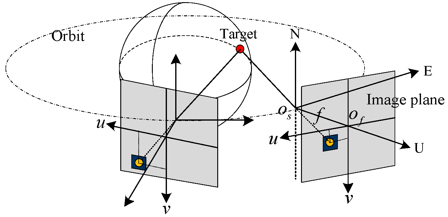
Figure 1. Coordinate system.
Sensors 18 03996 g001
Figure 2. Minimum distinguishable cell.
Sensors 18 03996 g002
Figure 3. Likelihood probability density distribution. (a) is target image on focal plane, (b) is likelihood probability density distribution.
Sensors 18 03996 g003
Figure 4. Block diagram of the CBMeMber filter.
Sensors 18 03996 g004
Figure 5. Motion modeling of boost phase.
Sensors 18 03996 g005
Figure 6. Trajectory in launch coordinate system.
Sensors 18 03996 g006
Figure 7. Trajectories (the red lines represent the boost phases of the ballistic missiles, and the yellow lines represent the free-flight phases).
Sensors 18 03996 g007
Figure 8. Detection scenario (the left picture is a panorama and the right one is a partial enlargement. The blue circle represents the detector orbit, the red ★ represents the detector, and the green line represents the line of sight).
Sensors 18 03996 g008
Figure 9. Traces of the targets on the focal plane.
Sensors 18 03996 g009
Figure 10. Measurements. (a) is all the measurements in the whole field of view, (b) is an enlargement of the dotted box in (a), (c) is an enlargement of the dotted box in (b).
Sensors 18 03996 g010
Figure 11. Trajectory tracking, cardinality estimated, and OSPA based on ambiguous measurement. (a) is trajectory tracking, (b) is cardinality estimated, (c) is OSPA.
Sensors 18 03996 g011
Figure 12. Trajectory tracking, cardinality estimated, and OSPA based on traditional measurement. (a) is trajectory tracking, (b) is cardinality estimated, (c) is OSPA.
Sensors 18 03996 g012
Table 1. Launch parameters.
Target 1Target 2Target 3Target 4
Launch point(N 0°, E 0°)(N 0°, E 0°)(N 0°, E 3°)(N 0°, E 3°)
Shooting30°60°330°300°
Captured timeT0T0 + 10 sT0 + 20 sT0 + 30 s