Article

A Novel Method for the Micro-Clearance Measurement of a Precision Spherical Joint Based on a Spherical Differential Capacitive Sensor

1
School of Mechanical Engineering, Hangzhou Dianzi University, Hangzhou 310018, China
2
School of Mechanical Engineering, Zhejiang University, Hangzhou 310027, China
3
State Key Lab of Fluid Power & Mechatronic Systems, Zhejiang University, Hangzhou 310027, China
*
Author to whom correspondence should be addressed.
Sensors 2018, 18(10), 3366; https://doi.org/10.3390/s18103366
Submission received: 15 September 2018 / Revised: 2 October 2018 / Accepted: 5 October 2018 / Published: 9 October 2018
(This article belongs to the Section Physical Sensors)

Abstract

:
A spherical joint is a commonly used mechanical hinge with the advantages of compact structure and good flexibility, and it becomes a key component in many types of equipment, such as parallel mechanisms, industrial robots, and automobiles. Real-time detection of a precision spherical joint clearance is of great significance in analyzing the motion errors of mechanical systems and improving the transmission accuracy. This paper presents a novel method for the micro-clearance measurement with a spherical differential capacitive sensor (SDCS). First, the structure and layout of the spherical capacitive plates were designed according to the measuring principle of capacitive sensors with spacing variation. Then, the mathematical model for the spatial eccentric displacements of the ball and the differential capacitance was established. In addition, equipotential guard rings were used to attenuate the fringe effect on the measurement accuracy. Finally, a simulation with Ansoft Maxwell software was carried out to calculate the capacitance values of the spherical capacitors at different eccentric displacements. Simulation results indicated that the proposed method based on SDCS was feasible and effective for the micro-clearance measurement of the precision spherical joints with small eccentricity.

1. Introduction

Because of the advantages of compact structure, good flexibility, and high carrying capacity, precision spherical joints are widely used for three-degree-of-freedom (DOF) mechanical hinges in many types of equipment, such as parallel mechanisms, industrial robots, and automobiles [1]. In actual applications of spherical joints, the clearance between the ball and the socket inevitably exists, due to manufacturing or installation errors. As a result, during the process of transmitting motion or force with spherical joints, the actual position and orientation of the output shaft may deviate from the ideal pose, which affects the overall transmission accuracy of the system. Therefore, real-time detection of a precision spherical joint clearance is of great significance in analyzing the motion errors of the application systems (e.g., robot joints) and improving the transmission accuracy [2].
The clearance measurement is essentially the detection of the relative linear displacement between two components. In the case of a precision spherical joint, the clearance measurement can be achieved by detecting the eccentric displacements of a ball (3-DOF motion in space) and the socket (fixed in space). Many methods have been proposed for the clearance measurement in industrial applications, for example, the inductive sensor-based method [3], the optical fiber-based method [4], the microwave-based method [5], and other methods based on eddy current sensors [6] or capacitive sensors [7]. However, studies focused on the clearance measurement of a precision spherical joint have been rarely reported. Recently, Endemano et al. [8] presented a two-dimensional (2D) study for calculating the capacitances of rotating objects with eccentricity. Han et al. [9] carried out a micro-displacement detection of a spherical rotor with regard to electrostatically suspended gyroscope technology. In the electrostatically suspended gyroscope’s rotor-bearing system, the spherical rotor was steadily suspended by electrostatic forces in a high vacuum chamber. The drift of the spherical rotor from the center of the cavity was obtained by detecting the variation of the spherical capacitance between electrodes and the rotor. This real-time drift was then used as a feedback signal to generate the feedback control of the electrostatic force. The spherical detecting electrode usually consisted of several electrodes (e.g., six, eight or twelve electrodes) [10,11,12,13,14]. Since the clearance of a spherical joint exhibits similar characteristics with that of a spherical rotor, this micro-displacement detection method used for the spherical rotor may provide an inspiration for spherical gap measurement.
A capacitive sensor is widely used for high-precision displacement detection in many applications [15,16]. It is a typical non-contact measurement device with high accuracy, good dynamic performance, high resolution, and strong adaptability to harsh environments (e.g., high temperature). Thus, in this paper, a spherical differential capacitive sensor (SDCS) is proposed to measure spatially eccentric displacements of the ball of a precision spherical joint. First, the structure and measuring principle of the SDCS is introduced. Then, the mathematical model for the relation between spatial eccentric displacements and differential capacitances is presented. Finally, the feasibility of the proposed method is validated by calculating the capacitance for different eccentric displacements using commercial software Ansoft Maxwell 16.0 (Ansoft, Pittsburgh, PA, USA).

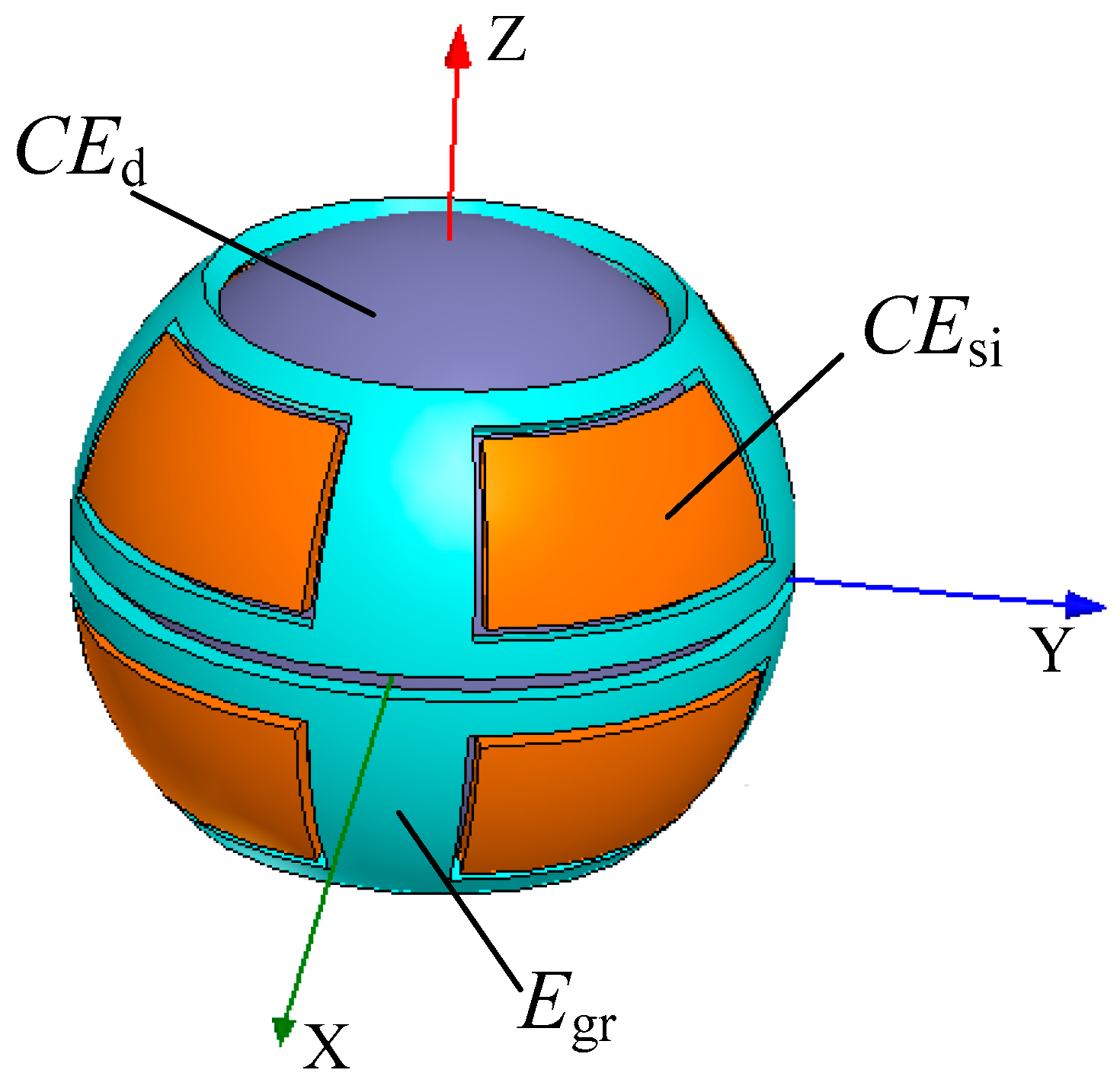
2. Structural Design and Measuring Principle

The SDCS proposed in this work consists of a ball (excitation electrode, CEd) and eight spherical capacitive plates (sensing electrodes, CEsi, i = 1, 2, …, 8), as shown in Figure 1a. The ball of the spherical joint is used as a common electrode, whereas each of the eight spherical capacitive plates is employed as a spherical capacitor Ci, i = 1, 2, …, 8. The coordinate system OXYZ is defined in Figure 1b, with the origin O chosen at the center of the spherical capacitive plates. Eight spherical capacitive plates having the same structure size are concentrically fixed in the spherical joint’s socket, and they are symmetrically distributed in eight quadrants of the three-dimensional coordinate system (Figure 1b). Teflon-laced epoxy with a certain thickness, known as an abrasion-resistant material with self-lubricating properties, was deposited on the inner surface of the spherical capacitive plates. This ensured the insulation between the excitation electrode and the sensing electrodes. Moreover, as a dielectric material, Teflon-laced epoxy can improve the sensitivity of the capacitive sensor.
Ideally, the center of the ball coincides with that of the spherical capacitive plates, and the clearances between the ball and each of the eight spherical capacitive plates have identical values. As such, eight spherical capacitors have the same value in capacitance. Once the ball has an eccentric displacement relative to the socket, the clearances between the eight spherical capacitive plates and the ball exhibit diverse variations, and thus the capacitance value of each spherical capacitor varies accordingly. In other words, the eccentric displacements of the ball can be obtained by detecting the capacitance of the eight spherical capacitors.
To obtain the micro-clearance of a precision spherical joint (i.e., the three-dimensional displacement of the ball), three pairs of differential capacitance units were established for the eccentric displacement measurement along the X, Y and Z directions, respectively. The differential capacitance unit pair denoted a pair of differential capacitance units that faced each other with a 180° phase shift. As shown in Table 1, Cup-X, Cup-Y and Cup-Z denoted the differential capacitance unit pairs along the X, Y and Z directions, respectively. Each pair consisted of unit 1 and unit 2, and each unit included four adjacent capacitors. The eccentric displacements of the ball were calculated from the capacitance values of each differential capacitance unit pair. Specifically, the eccentric displacement δX of the ball along the X direction was obtained by calculating the capacitance difference between the two differential capacitance units along the X direction, one being the unit that consisted of C1, C4, C5 and C8, and the other being the unit that consisted of C2, C3, C6 and C7. Similarly, the eccentric displacement δY of the ball along the Y direction and the eccentric displacement δZ of the ball along the Z direction was acquired by calculating the capacitance difference of the corresponding differential capacitance unit pair, respectively. Thus, the eccentric displacement component δX, δY and δZ of the ball can be given by the following equations:
δ X = f X ( C 1 + C 4 + C 5 + C 8 C 2 C 3 C 6 C 7 ) ,
δ Y = f Y ( C 1 + C 2 + C 5 + C 6 C 3 C 4 C 7 C 8 ) ,
δ Z = f Z ( C 1 + C 2 + C 3 + C 4 C 5 C 6 C 7 C 8 ) ,
where fX, fY and fZ denote the transition function for the measured capacitance and the eccentric displacement component in the X, Y and Z directions, respectively. Their values were determined by the structural parameters of the eight spherical capacitors. In order to simplify the expressions of the differential capacitances along the X, Y and Z directions, ΔCX, ΔCY and ΔCZ are defined as follows:
Δ C X = C 1 + C 4 + C 5 + C 8 C 2 C 3 C 6 C 7 ,
Δ C Y = C 1 + C 2 + C 5 + C 6 C 3 C 4 C 7 C 8 ,
Δ C Z = C 1 + C 2 + C 3 + C 4 C 5 C 6 C 7 C 8 .
To approximately calculate the capacitance value of each spherical capacitor, two assumptions were made: (1) the area element dA of a spherical capacitor was regarded as a parallel-plate capacitor with an equal gap; (2) the fringe effect of the spherical capacitive plates was not taken into consideration. Based on the above assumptions, the capacitance of the spherical capacitor element dC was calculated based on the formula of a parallel-plate capacitor. Then, the capacitance value of each spherical capacitor was obtained using the following integral:
C i = ε A i 1 e d A ( i = 1 , 2 , , 8 ) ,
where ε is the permittivity of the dielectric which includes the abrasion-resistant material and a small quantity of air, e is the clearance between the ball and each spherical capacitive plate, and Ai is the effective area of the spherical capacitive plate for each spherical capacitor Ci, i = 1, 2,…, 8.

3. Mathematical Model

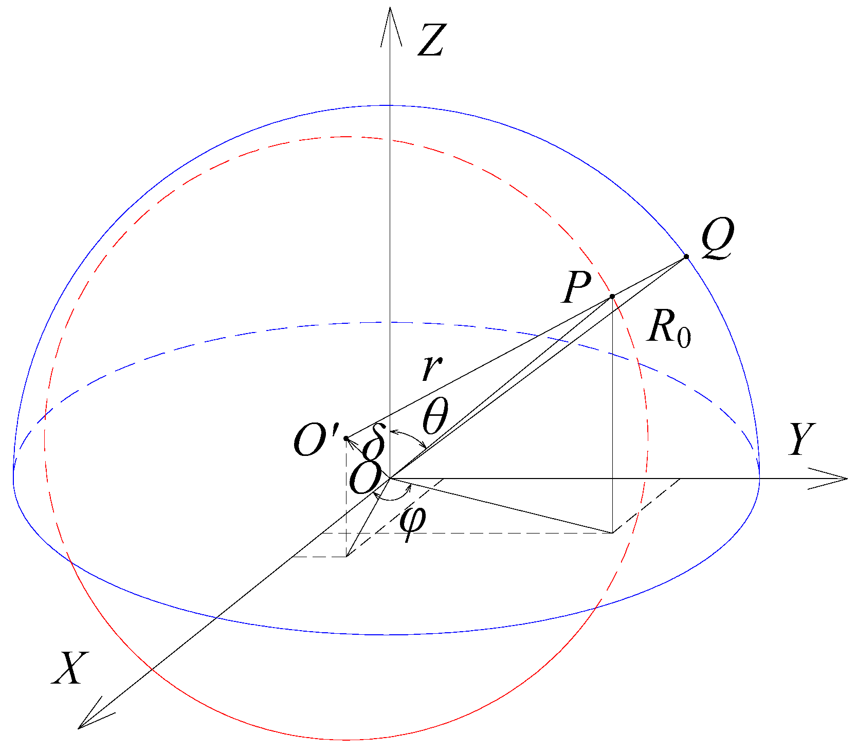
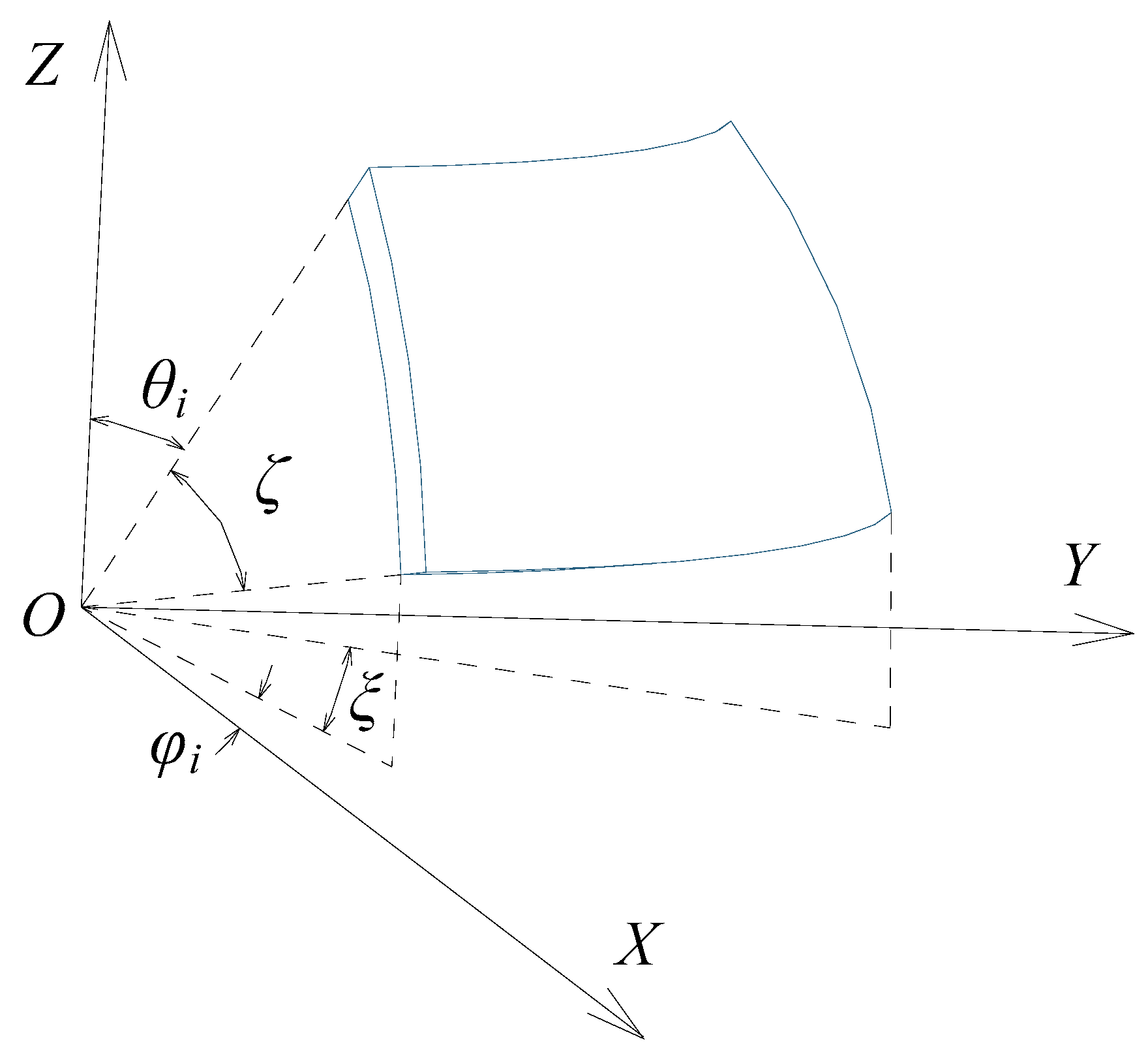
3.1. Calculation of the Clearance between the Ball and the Spherical Capacitive Plates

Figure 2 presents the coordinate system OXYZ in which the center of the ball deviates from that of the spherical capacitive plates. The unit vectors along the X, Y and Z directions are denoted by i, j and k, respectively. θ is the zenithal angle between the output shaft central axis of the spherical joint and the positive direction of the Z axis, 0 θ π . φ is the azimuthal angle between the projection of the output shaft central axis onto the plane XOY and the positive direction of the X axis, 0 φ 2 π . The point P is on the surface of the ball, and the outward unit normal vector n of the vector OP in the coordinate system OXYZ is given by the following equation:
n = sin θ cos φ i + sin θ sin φ j + cos θ k .
The inner surface of the spherical capacitive plates and the outer surface of the ball are considered as ideal spheres. As shown in Figure 2, R0 denotes a spherical radius of the inner surface of the spherical capacitive plates. r is the radius of the ball. δ is the linear displacement between the center O of the socket and the center O’ of the ball. Therefore, the spatially eccentric displacement of the ball can be written in the form of a vector as follows:
δ = δ X i + δ Y j + δ Z k .
As shown in Figure 2, the line joining the two points O’ and P is extended to intersect with the inner surface of the spherical capacitive plates at the point Q. The distance from point Q to point P is defined as the clearance e at the point P. The initial clearance of the ball without eccentricity is denoted by e0, that is, e 0 = R 0 r . If the ball has an eccentric displacement relative to the socket, the clearance at the point P in the case of e R 0 can be given by the following equation:
e = R 0 δ X sin θ cos φ δ Y sin θ sin φ δ Z cos θ r .
To simplify the subsequent calculations, dimensionless parameters are introduced as follows:
k = e e 0 , λ X = δ X e 0 , λ Y = δ Y e 0 , λ Z = δ Z e 0 .
Therefore, Equation (10) can be rewritten in the following dimensionless form:
k = 1 λ X sin θ cos φ λ Y sin θ sin φ λ Z cos θ .

3.2. Relation between Capacitance of Spherical Capacitors and Eccentric Displacements

Let λ = λ X sin θ cos φ + λ Y sin θ sin φ , assuming obviously that λ < 1. It is also assumed that the eccentric displacement of the ball is small.
Using Taylor’s expansion method for 1/k, it becomes the following Taylor’s series:
1 k = 1 1 λ = 1 + λ + λ 2 + λ 3 + .
Substituting Equations (11) and (12) into Equation (7), the following equation is obtained:
C i = ε e 0 A i [ 1 + E ( θ , φ ) ] d A ( i = 1 , 2 , , 8 ) ,
where E ( θ , φ ) = n = 1 ( λ X sin θ cos φ + λ Y sin θ sin φ + λ Z cos θ ) n and dA is the area element of the spherical capacitive plates at the point Q (i.e., d A = R 0 2 sin θ d θ d φ ).
The capacitance of each spherical capacitor can be obtained according to Equation (13). Then, the differential capacitance ΔCX, ΔCY and ΔCZ can be calculated by substituting the capacitance of each spherical capacitor into Equations (4)–(6), respectively. Therefore, the mathematical model of the relation between the differential capacitance and the spatial eccentric displacements can be established.
Equation (13) can be further rewritten as follows:
C i = K i ( λ X , λ Y , λ Z ) ε R 0 2 e 0 ( i = 1 , 2 , , 8 ) ,
where K i ( λ X , λ Y , λ Z ) = A i [ 1 + E ( θ , φ ) ] sin θ d θ d φ .
As for the spherical capacitive plate CEsi (i = 1, 2, …, 8) shown in Figure 3, ζ is the corresponding angle of arc length in the longitude direction, and θ i denotes the initial zenithal angle between the upper edge of the spherical capacitive plate and the positive direction of the Z axis. ξ is the corresponding angle of arc length in the latitude direction, and φ i denotes the azimuthal angle between the projection of the left edge of the spherical capacitive plate onto the plane XOY and the positive direction of the X axis. Accordingly, K i ( λ X , λ Y , λ Z ) can be expressed as follows:
K i ( λ X , λ Y , λ Z ) = θ i θ i + ζ φ i φ i + ξ [ 1 + E ( θ , φ ) ] sin θ d θ d φ .
Ki (λX, λY, λZ) can be solved according to Equation (15), after the layout and size of the spherical capacitive plates are determined. Since the eight spherical capacitive plates have the same structure size and are symmetrically distributed in space, and if the size and layout of the spherical capacitive plate CEs1 is known, other spherical capacitive plates can be determined. Considering the height restrictions of the spherical joint top-cover, let θ 1 = 5 π / 18 , ζ = π / 6 , φ 1 = π / 12 , and ξ = π / 3 . Taking the spherical capacitor C1 as an example, the corresponding K 1 ( λ X , λ Y , λ Z ) is calculated as follows by neglecting the terms of degree above 3:
K 1 ( λ X , λ Y , λ Z ) = 0.4913 + 0.2987 λ X + 0.2987 λ Y + 0.2005 λ Z +   0.2002 λ X 2 + 0.2002 λ Y 2 + 0.0909 λ Z 2 + 0.3311 λ X λ Y +   0.2383 λ X λ Z + 0.2383 λ Y λ Z + 0.1434 λ X 3 + 0.1434 λ Y 3 +   0.0445 λ Z 3 + 0.3073 λ X λ Y 2 + 0.3073 λ X 2 λ Y + 0.1588 λ X λ Z 2 +   0.2341 λ X 2 λ Z + 0.1588 λ Y λ Z 2 + 0.2341 λ Y 2 λ Z + 0.3873 λ X λ Y λ Z
Similarly, K i ( λ X , λ Y , λ Z )   ( i = 2 , , 8 ) for the other spherical capacitors can be obtained. Then, the capacitance value for each capacitor can be calculated according to Equation (14). By further substituting each capacitance into Equations (4)–(6), the following equations are obtained:
Δ C X = ε R 0 2 e 0 Δ K X ,
Δ C Y = ε R 0 2 e 0 Δ K Y ,
Δ C Z = ε R 0 2 e 0 Δ K Z ,
where
Δ K X = 2.3896 λ X + 1.1472 λ X 3 + 2.4584 λ X λ Y 2 + 1.2704 λ X λ Z 2 ,
Δ K Y = 2.3896 λ Y + 1.1472 λ Y 3 + 2.4584 λ Y λ X 2 + 1.2704 λ Y λ Z 2 ,
Δ K Z = 1.6040 λ Z + 0.3560 λ Z 3 + 1.8728 λ Z λ X 2 + 1.8728 λ Z λ Y 2 .
It can be seen from Equations (20)–(22) that the even-order terms of dimensionless eccentric displacements of the ball in the socket are eliminated. This can be ascribed to the symmetrically spatial distribution of the eight spherical capacitive plates and the differential calculation for the capacitance of the spherical capacitors. Thus, the proposed method can improve the sensitivity of the sensor and effectively reduce nonlinear errors.
To examine the effect of the third-order terms, the dimensionless eccentric displacements of the ball with and without the third-order terms were compared in detail. Two cases were considered, one being the displacements only in each axis direction (λX = 0, λY = 0 or λZ = 0), the other being the displacements in a non-axis direction (λX ≠ 0, λY ≠ 0 and λZ ≠ 0).
Figure 4 compares the first-order term and the sum of the four terms of dimensionless eccentric displacements in the case of the displacement in the single-axis direction. First, if the displacement of the ball occurs in the X direction (λX ≠ 0 and λY = λZ = 0), the relative error between ΔKX and its first-order term is 0.48% and 1.88% at λX = 0.1 and 0.2, respectively (Figure 4a). Second, if the displacement occurs in the Y direction (λY ≠ 0 and λX = λZ = 0), the relative error between ΔKY and its first-order term is the same as that of the X direction and is therefore not shown. Third, if the displacement occurs in the Z direction (λZ ≠ 0 and λX = λY = 0), the relative error between ΔKZ and its first-order term is 0.22% and 0.88% at λZ = 0.1 and 0.2, respectively (Figure 4b).
The complex case is that the ball has a small displacement in all three axis directions, assuming that the eccentricity of the ball ρ = λ X 2 + λ Y 2 + λ Z 2 is within the range of 0 ≤ ρ ≤ 1. Figure 5 presents the comparison between ΔKX and its first-order term at ρ = 0.1 and ρ = 0.2, respectively. The difference between ΔKX and its first-order term (i.e., third-order terms) is also included. Two observations can be made. First, ΔKX is roughly equal to its first-order term on the condition of a small eccentric displacement of the ball. Specifically, the relative error between ΔKZ and its first-order term is less than 1% and 4% at ρ = 0.1 and 0.2, respectively. Second, ΔKX exhibits a linear dependence on λX, whereas the effect of λY and λZ on ΔKX is negligible. Similarly, the corresponding conclusions for ΔKY and ΔKZ can be inferred, respectively.
The above discussions indicate that the third-order terms of the eccentric displacements have little influence on the differential capacitance of the sensor if the eccentricity of the ball ρ ≤ 0.2. In addition, it is reasonable to use a linear function to describe the relationship between the differential capacitance and the spatially eccentric displacement component. Hence, if the eccentric displacement components δX, δY and δZ vary within a small range, Equations (17)–(19) can be rewritten in the following form:
Δ C X = 2.3896 ε R 0 2 e 0 2 δ X ,
Δ C Y = 2.3896 ε R 0 2 e 0 2 δ Y ,
Δ C Z = 1.6040 ε R 0 2 e 0 2 δ Z .

4. Simulation Setup

In practical applications, capacitive sensor plates have a certain thickness and a limited structure size. There are many charges unevenly distributed on each surface, and the density of the charges is much greater at the edge or tip end. Moreover, the electric field lines at the edge of the plate diverge outwards, resulting in the “fringe effect”. Therefore, the capacitance of the capacitive sensor is inevitably affected by the fringe effect [17]. The fringe effect not only decreases the sensitivity of capacitive sensor, but also generates nonlinear output which affects measuring accuracy. To reduce the errors caused by the fringe effect, equipotential guard rings are widely used in the design of capacitive sensors with spacing variation [18]. Therefore, guard rings (Egr in Figure 6) for the proposed SDCS were designed on the periphery of the spherical capacitive plates. The radius of both inner and outer surfaces was equal to that of the spherical capacitive plates.
Ansoft Maxwell software was used to calculate the capacitance value at different eccentric displacements for the SDCS with and without guard rings. The spherical capacitive plates had an inner radius of 25.5 mm and a thickness of 2 mm. The radius of the ball was 25 mm, and other structural parameters of the SDCS are presented in Table 2. Abrasion-resistant material was used to fill in the gap between the ball and the spherical capacitive plates. However, air exited through the gap due to the assembly clearance. In order to simplify the simulation model and theoretical calculation, air was adopted as the dielectric. The permittivity of the air was 1.00053. The displacement varied from −50 μm to 50 μm, with a step of 2 μm.

5. Results and Discussions

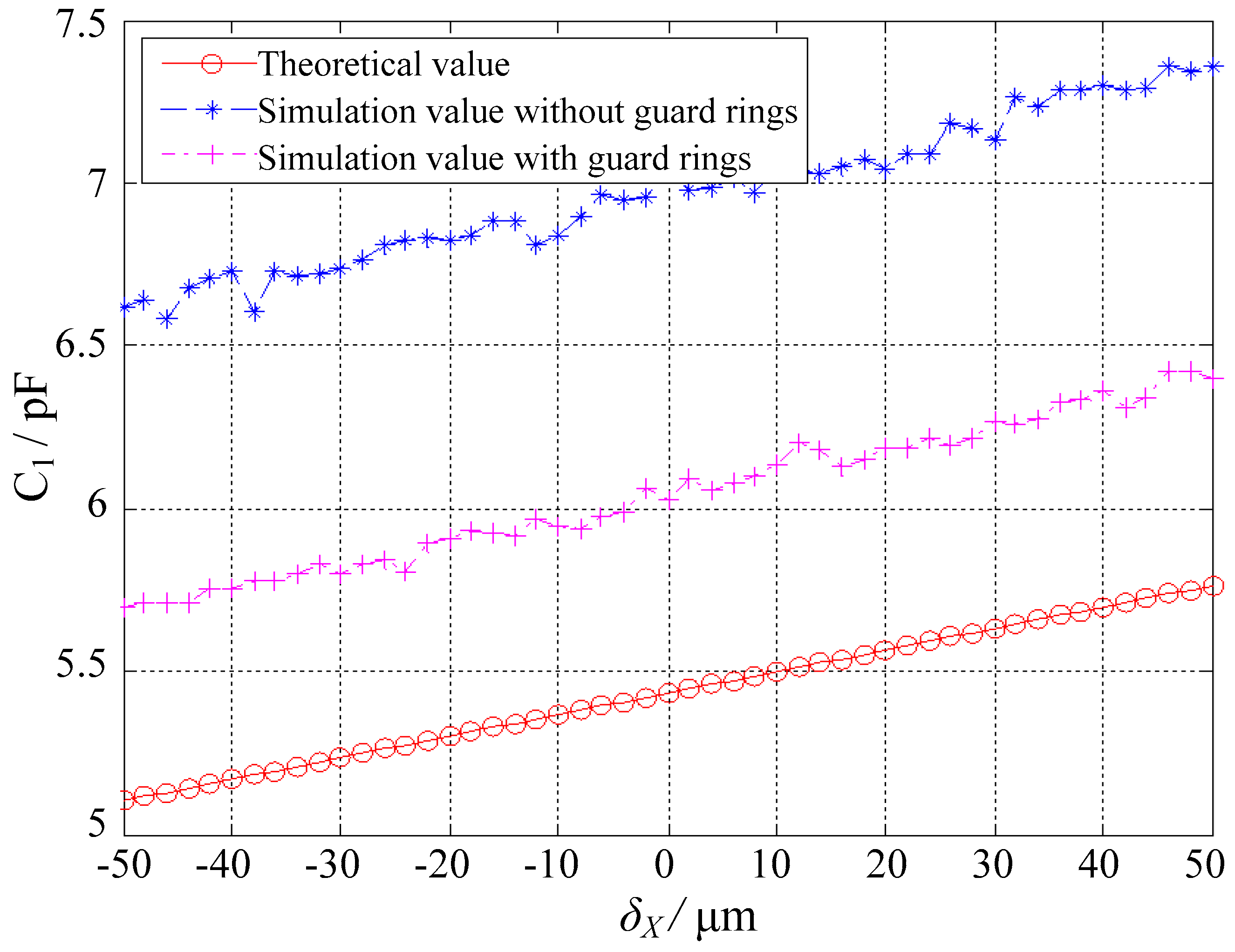
5.1. Effect of Guard Rings

Figure 7 presents the simulated capacitance values of the spherical capacitor C1 at different eccentric displacements, along with the theoretical results. Essential comparisons were made between the cases with and without guard rings. Two observations were made. First, the simulation capacitance values were larger than the theoretical values, which were mainly attributed to the fringe effect. This is consistent with Weng and Jin [19], that is, the fringe effect could lead to an increase in capacitance. Second, the increased capacitance was effectively reduced with guard rings, suggesting that the fringe effect could be weakened by deploying guard rings.

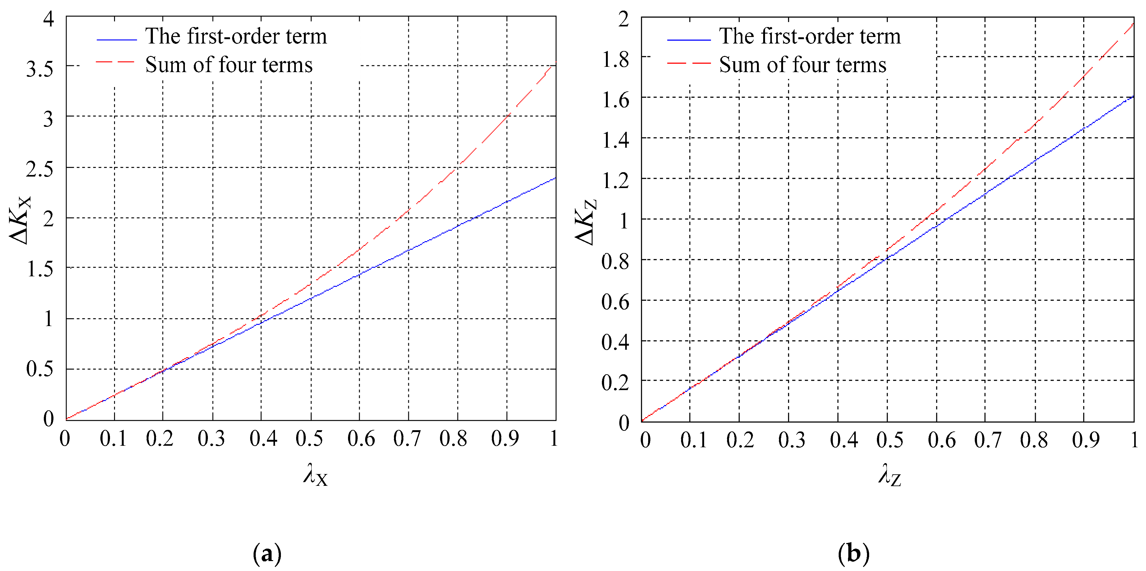
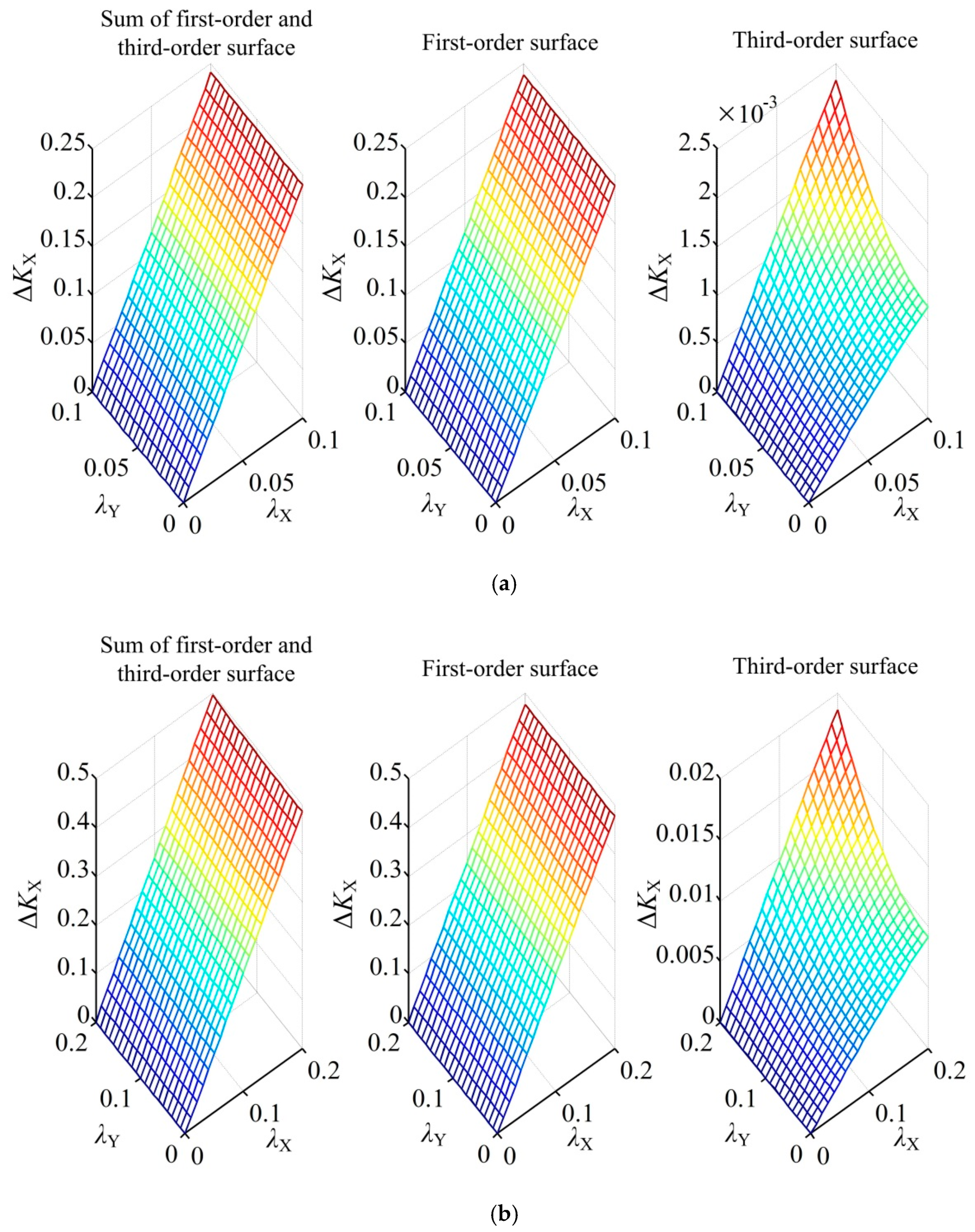
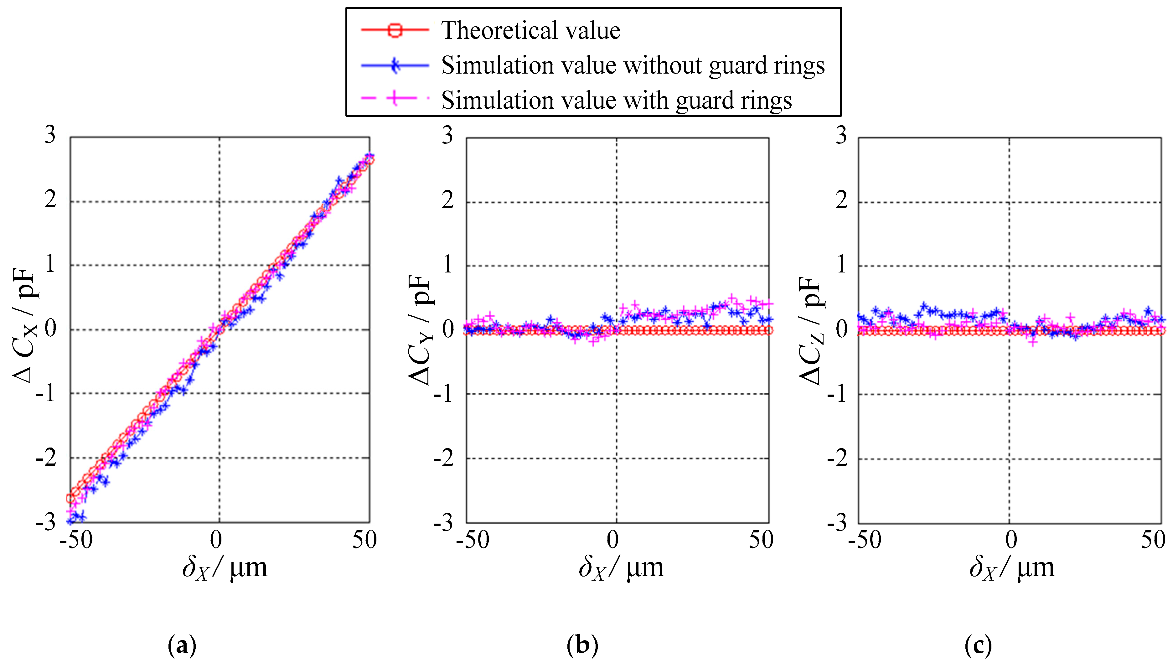
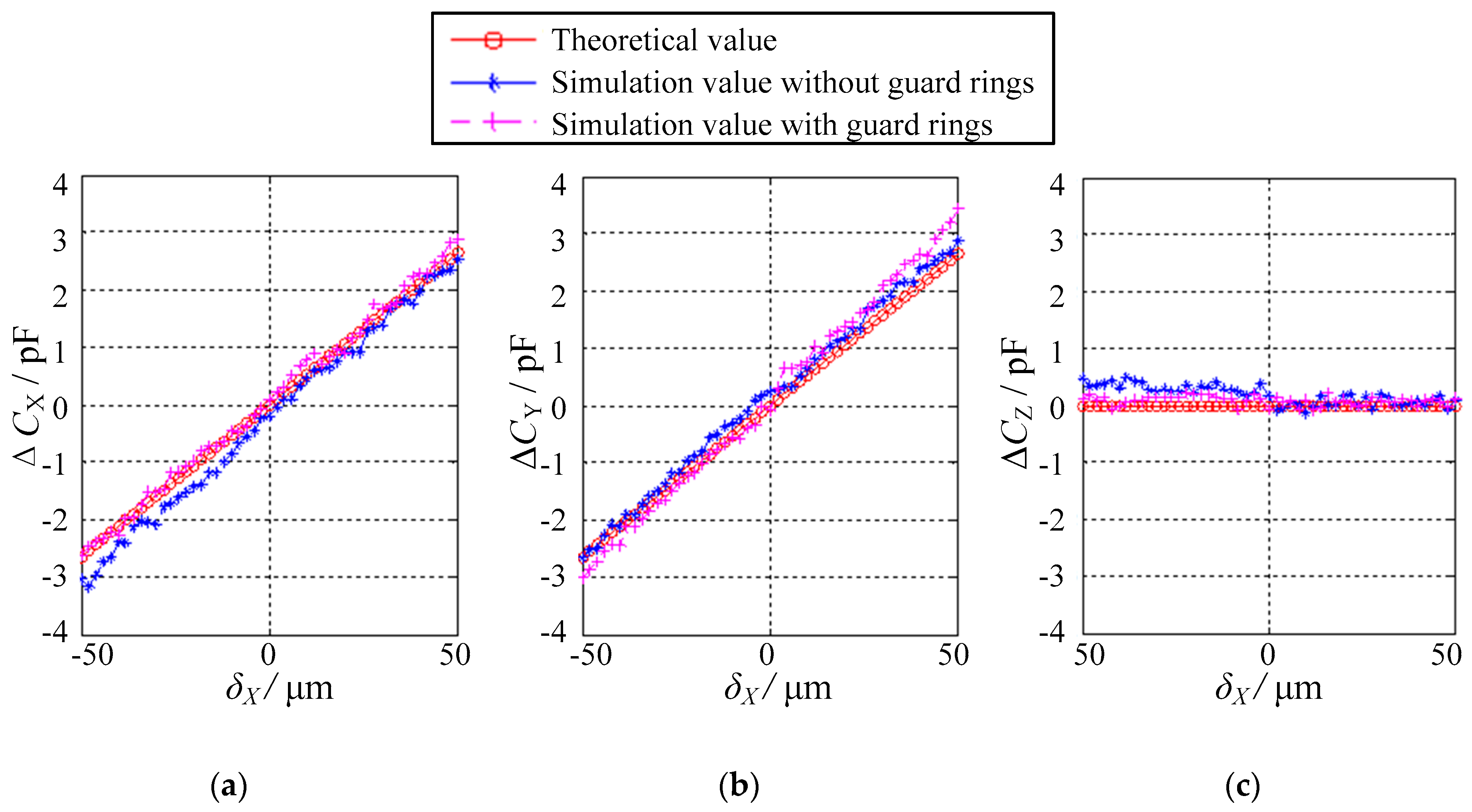
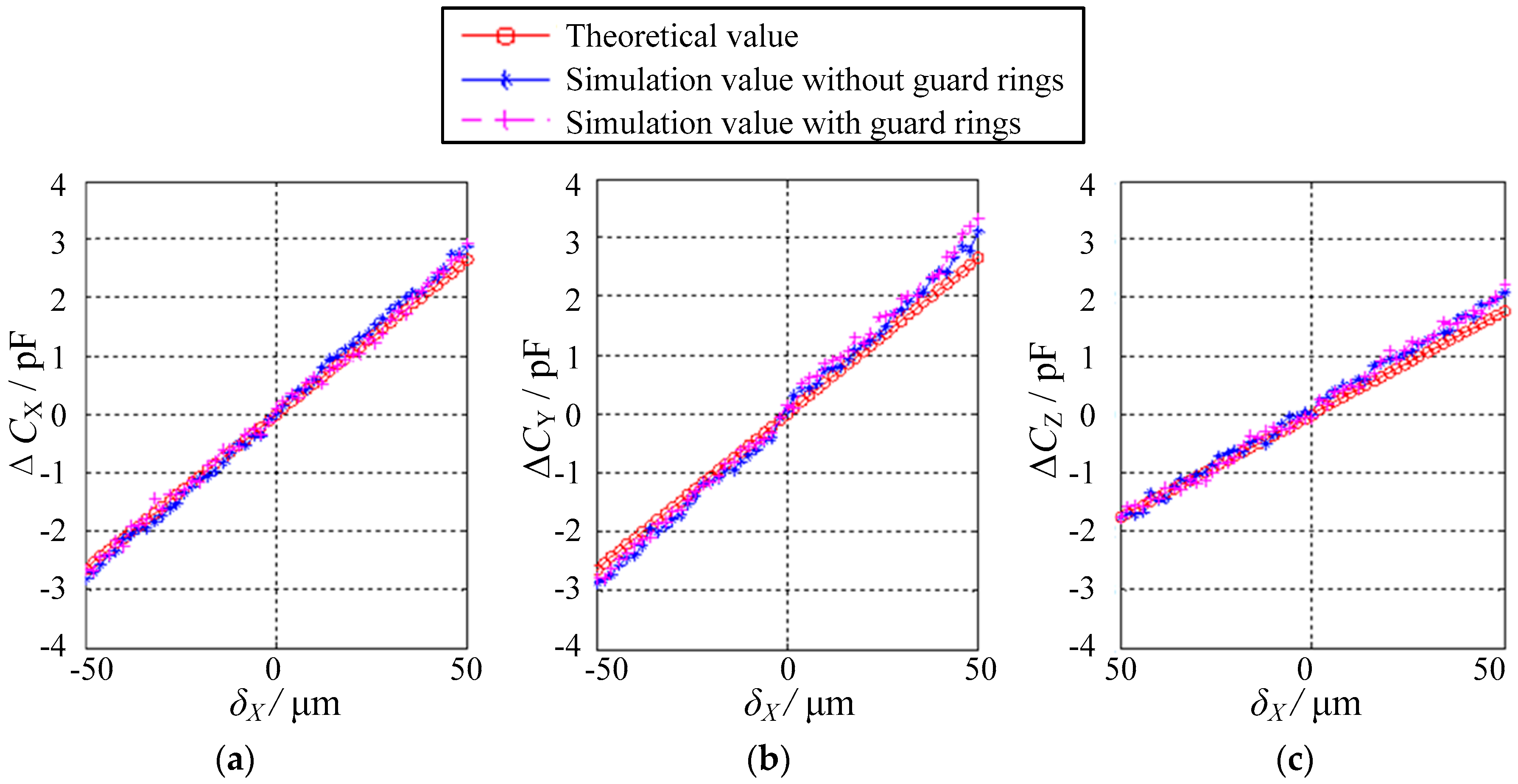
5.2. Dependence of the Differential Capacitances on the Eccentric Displacements

In this section, the dependence of the differential capacitances on the eccentric displacements is investigated in detail. To facilitate the discussion, the spatially eccentric displacement of the ball is divided into two categories based on the eccentric directions, namely, one along the single-axis direction and the other along the non-axis direction.
The simplest case is that the ball exhibits eccentric displacements in one of three orthogonal axes (i.e., X, Y or Z direction). The authors have selected the eccentric displacements along the X direction δX as an example. δX varies from −50 μm to 50 μm, with a step of 2 μm. Evidently, the eccentricity of the ball is less than 0.1. Figure 8 presents the dependence of the differential capacitance ΔCX, ΔCY and ΔCZ on the displacements along the X direction δX. Three observations can be made. First, the variation of the simulated values of ΔCX, ΔCY and ΔCZ exhibits similar trends with that of the theoretical values. In other words, the simulation values are consistent with the theoretical values. Second, the differential capacitance ΔCX exhibits a linear relationship with the displacement δX, suggesting a good linearity of the proposed sensor. Third, the simulated values of ΔCY or ΔCZ are close to the theoretical values, that is, 0 pF over the range of −50 μm ≤ δX ≤ 50 μm. This indicates that no displacement of the ball occurs along the Y or Z direction. The simulated values exhibit small deviations of 0.5 pF in ΔCY and 0.4 pF in ΔCZ from the theoretical values, which may be ascribed to the simulation errors.
Figure 9 and Figure 10 present the simulated values of the differential capacitances ΔCX, ΔCY, and ΔCZ on the condition that the eccentric displacements are along non-axis directions, the former being along the direction of X = Y in the XOY plane (δX = δY and δZ = 0) and the latter being along the direction of X = Y = Z in three-dimensional (3D) space (δX = δY = δZ). The maximum eccentricity is 0.14 for the eccentric displacements in the XOY plane and 0.17 for those in space, respectively. Several observations can be made. First, the simulated values of ΔCX, ΔCY and ΔCZ are roughly equal to their theoretical values. Second, if the eccentric displacements are along the direction of X = Y in the XOY plane, both ΔCX and ΔCY exhibit a linear correlation with δx, whereas the variation of ΔCZ over the range of −50 μm ≤ δX ≤ 50 μm approximately remains unchanged (Figure 9). Third, if the eccentric displacements are along the direction of X = Y = Z in 3D space, all the differential capacitances ΔCX, ΔCY and ΔCZ show a linear relationship with δX (Figure 10). Finally, the gradient of ΔCZ is lower than that of ΔCX and ΔCY. This indicates that the sensitivity along the Z direction is lower than that along the X and Y directions, which is consistent with Equations (23)–(25).
In summary, it can be inferred from the simulation result that the eccentric displacement component along the X, Y or Z direction has a good linear relationship with corresponding differential capacitance, provided that the eccentricity of the ball is small. Furthermore, due to the symmetrically spatial layout of the spherical capacitive plates and the differential calculation for the capacitance of the spherical capacitors, additional capacitance caused by the fringe effect can be effectively reduced.

6. Conclusions

This work proposes a novel method for the micro-clearance measurement of a precision spherical joint based on an SDCS. The configuration of the SDCS was first designed and a mathematical model of the proposed measurement method was then deduced. Finally, a simulation using Ansoft Maxwell software was conducted to verify the feasibility of the proposed method. The following conclusions can be made.
(1) The developed SDCS included a ball and eight spherical capacitive plates that were fixed onto the inner side of the socket. The ball was deployed as an excitation electrode, whereas each of the eight capacitive plates was used as a sensing electrode. As such, each capacitive plate and the ball formed a capacitor. The eccentric displacements of the ball were obtained by detecting the capacitance of eight spherical capacitors.
(2) A mathematical model of the differential capacitances and eccentric displacements was deduced. Due to the symmetrically spatial layout of the spherical capacitive plates and the differential calculation for the capacitance of the spherical capacitors, the even-order terms of dimensionless eccentric displacements of the ball in the socket were eliminated. Furthermore, if the eccentricity of the ball was less than 0.2, the third-order terms of the eccentric displacements had little effect on the differential capacitance of the sensor and were therefore neglected. As such, the differential capacitances ΔCX, ΔCY and ΔCZ exhibited a linear correlation with the eccentric displacement components δX, δY and δZ, respectively.
(3) The simulated values approximately coincided with the theoretical values, showing a linear correlation between the differential capacitances ΔCX, ΔCY and ΔCZ and the eccentric displacements. This suggests the feasibility of the proposed method for the clearance measurement of a spherical joint. Moreover, the simulated values with guard rings are closer to the theoretical values than those without guard rings. This indicates that the capacitance derivation caused by the fringe effect can be effectively reduced by employing guard rings, that is, the measurement accuracy can be improved by deploying guard rings.
Thus, this work presents analytical and numerical investigations on a capacitive sensor for the clearance measurement of spherical joints. Further studies are still required on experimental investigations about the performance of an actual sensor. Moreover, the sensor performance may be affected by geometrical tolerances (e.g., spherical tolerances of the ball and symmetrical tolerances of the capacitive plates). Extensive studies are required to assess a specification on needed tolerances and to compare it with typical spherical joint tolerances. Finally, mathematical deductions using Pade approximation and Schwarz–Chistoffel mapping may be also interesting objectives of further studies that aim at improving the prediction or theoretical calculation of sensor performance.

Author Contributions

Conceptualization, W.W.; Methodology, W.W. and K.L.; Numerical Simulation, M.Z. and K.X.; Data Analysis, M.Z. and G.S.; Writing—Original Draft Preparation, M.Z. and H.Y.; Writing—Review and Editing, H.Y., Z.C. and W.W.; Supervision, W.W. and B.J.; Funding Acquisition, W.W. and B.J. All authors regularly discussed the progress during the entire work.

Funding

This research was supported by the Zhejiang Provincial Natural Science Foundation of China under Grant No. LZ16E050001, and the National Natural Science Foundation of China under Grant Nos. U1709206, 51465027, and 51275465.

Conflicts of Interest

The authors declare no conflict of interest.

References

  1. Robertson, A.P.; Slocum, A.H. Measurement and characterization of precision spherical joints. Precis. Eng. 2006, 30, 1–12. [Google Scholar] [CrossRef]
  2. Zhu, J.; Ting, K.L. Uncertainty analysis of planar and spatial robots with joint clearances. Mech. Mach. Theory 2000, 35, 1239–1256. [Google Scholar] [CrossRef]
  3. Han, Y.; Zhong, C.; Zhu, X.; Zhe, J. Online monitoring of dynamic tip clearance of turbine blades in high temperature environments. Meas. Sci. Technol. 2018, 29, 045102. [Google Scholar] [CrossRef] [Green Version]
  4. Garcia, I.; Przysowa, R.; Amorebieta, J.; Zubia, J. Tip-clearance measurement in the first stage of the compressor of an aircraft engine. Sensors 2016, 16, 1897. [Google Scholar] [CrossRef] [PubMed]
  5. Zhang, J.; Duan, F.; Niu, G.; Jiang, J.; Li, J. A blade tip timing method based on a microwave sensor. Sensors 2017, 17, 1097. [Google Scholar] [CrossRef] [PubMed]
  6. Jamia, N.; Friswell, M.I.; El-Borgi, S.; Fernandes, R. Simulating eddy current sensor outputs for blade tip timing. Adv. Mech. Eng. 2018, 10, 1–12. [Google Scholar] [CrossRef]
  7. Lawson, C.P.; Ivey, P.C. Tubomachinery blade vibration amplitude measurement through tip timing with capacitance tip clearance probes. Sens. Actuators A Phys. 2005, 118, 14–24. [Google Scholar] [CrossRef]
  8. Endemano, A.; Desmulliez, M.P.Y.; Dunnigan, M. System level simulation of a double stator wobble electrostatic micromotor. Sens. Actuators A Phys. 2002, 99, 312–320. [Google Scholar] [CrossRef]
  9. Han, F.T.; Gao, Z.Y.; Li, D.M.; Wang, Y.L. Nonlinear compensation of active electrostatic bearings supporting a spherical rotor. Sens. Actuators A Phys. 2005, 119, 177–186. [Google Scholar] [CrossRef]
  10. Han, F.T.; Gao, Z.Y.; Wang, Y.L. Modelling and linearization for long-range spherical gap measurement. Chin. J. Sci. Instrum. 2002, 23, 257–260. (In Chinese) [Google Scholar] [CrossRef]
  11. Gao, Z.Y. Electrostatically Suspended Gyroscope Technology; Tsinghua University Press: Beijing, China, 2004; ISBN 9787302087786. (In Chinese) [Google Scholar]
  12. Hill, D.A.; Letendre, T.; Mills, H.A. Embedded, real-time DSP control of an electrostatically suspended gyroscope. In Proceedings of the 2004 American Control Conference, Boston, MA, USA, 30 June–2 July 2004; Volume 4, pp. 3321–3326. [Google Scholar]
  13. Liu, J.H.; Wang, H.; Chang, K.; Li, X.; Wang, Q.L. Design and test of displacement transducer for an electrode-insulated electrostatically suspended gyroscope. In Proceedings of the 2015 IEEE International Conference on Applied Superconductivity and Electromagnetic Devices, Shanghai, China, 20–23 November 2015; pp. 429–430. [Google Scholar]
  14. Han, F.T.; Wu, Q.P.; Gao, Z.Y. Initial levitation of an electrostatic bearing system without bias. Sens. Actuators A Phys. 2006, 130–131, 513–522. [Google Scholar] [CrossRef]
  15. Baxter, L.K. Capacitive Sensors: Design and Applications; IEEE Press: New York, NY, USA, 1997; ISBN 9780780353510. [Google Scholar]
  16. Heerens, W.C. Application of capacitance techniques in sensor design. J. Phys. E Sci. Instrum. 1986, 19, 897–906. [Google Scholar] [CrossRef]
  17. Wang, W.; Wen, Y.H.; Yu, J.P.; Chen, Z. Impact of fringe effect on measuring accuracy of planar capacitive sensors. Sens. Lett. 2011, 9, 1458–1461. [Google Scholar] [CrossRef]
  18. Ma, Y.Z.; Yu, Y.X.; Wang, X.H. Key technique for inner hole diameter measure with capacitive probe. Appl. Mech. Mater. 2013, 303–306, 827–830. [Google Scholar] [CrossRef]
  19. Weng, C.W.; Jin, A.K. Effect of fringing fields on the capacitance of circular microsrip disk. IEEE Trans. Microw. Theory 1980, 28, 98–104. [Google Scholar] [CrossRef]
Figure 1. Structural model of the proposed SDCS: (a) assembly diagram and (b) distribution of the spherical capacitive plates.
Sensors 18 03366 g001
Figure 2. Schematic diagram of the spherical clearance calculation.
Sensors 18 03366 g002
Figure 3. Coordinate system with a spherical capacitive plate CEs1.
Sensors 18 03366 g003
Figure 4. First-order term and the sum of four terms of (a) ΔKX and (bKZ if the displacements occur along the single-axis direction.
Sensors 18 03366 g004
Figure 5. Sum of four terms, first-order term and third-order terms of ΔKX with (a) ρ = 0.1 and (b) ρ = 0.2 if the displacements occur along the non-axis direction.
Sensors 18 03366 g005
Figure 6. Simulation model of the SDCS with guard rings.
Sensors 18 03366 g006
Figure 7. Effect of the guard rings on the capacitance value of the spherical capacitor C1.
Sensors 18 03366 g007
Figure 8. Relationship between the differential capacitance values and the displacements in the case of δY = δZ = 0: (a) ΔCX, (b) ΔCY and (c) ΔCZ.
Sensors 18 03366 g008
Figure 9. Relationship between the differential capacitance values and the displacements in the case of δX = δY and δZ = 0: (a) ΔCX, (b) ΔCY and (c) ΔCZ.
Sensors 18 03366 g009
Figure 10. Relationship between the differential capacitance values and the displacements in the case of δX = δY = δZ: (a) ΔCX, (b) ΔCY and (c) ΔCZ.
Sensors 18 03366 g010
Table 1. Spherical capacitors included in three pairs of differential capacitance units along X, Y and Z directions, respectively.
Unit PairCapacitors for Unit 1Capacitors for Unit 2
Cup-XC1, C4, C5 and C8C2, C3, C6 and C7
Cup-YC1, C2, C5 and C6C3, C4, C7 and C8
Cup-ZC1, C2, C3 and C4C5, C6, C7 and C8
Table 2. Simulation parameters of the SDCS.
ParametersValues
The angle of spherical capacitive plates in the longitude direction ζπ/6
The angle of spherical capacitive plates in the latitude direction ξπ/3
The angle of the clearance between the guard ring ηπ/90

