The Combination of Micro Diaphragm Pumps and Flow Sensors for Single Stroke Based Liquid Flow Control

Abstract
:1. Introduction
1.1. Micro Diaphragm Pump
1.2. Miniaturizable Inline Flow Sensor Technologies
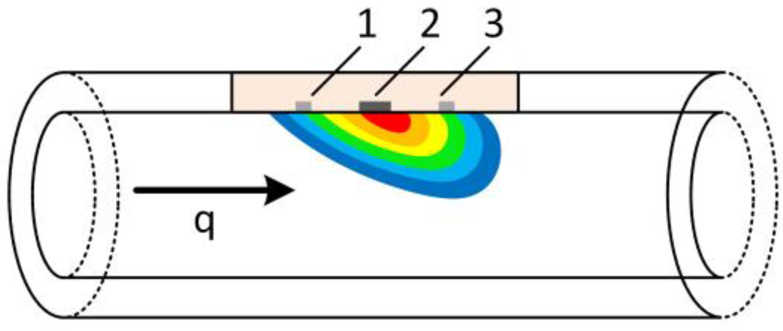
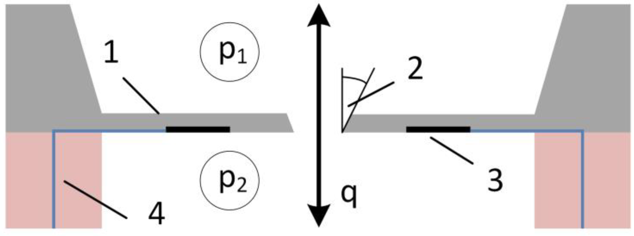
1.2.1. Differential Pressure Based (DPB) Flow Sensor
1.2.2. Thermal Flow Sensors
1.3. Flow Control Methods
2. Materials and Methods
2.1. Materials and Equipment
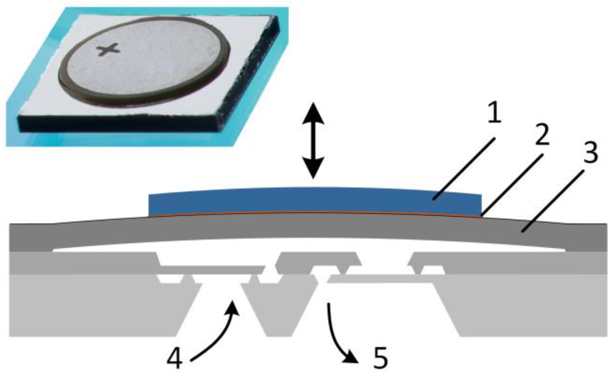
2.1.1. Silicon Micropump
2.1.2. Differential Pressure Based (DPB) Flow Sensor
2.2. Measurement Methods
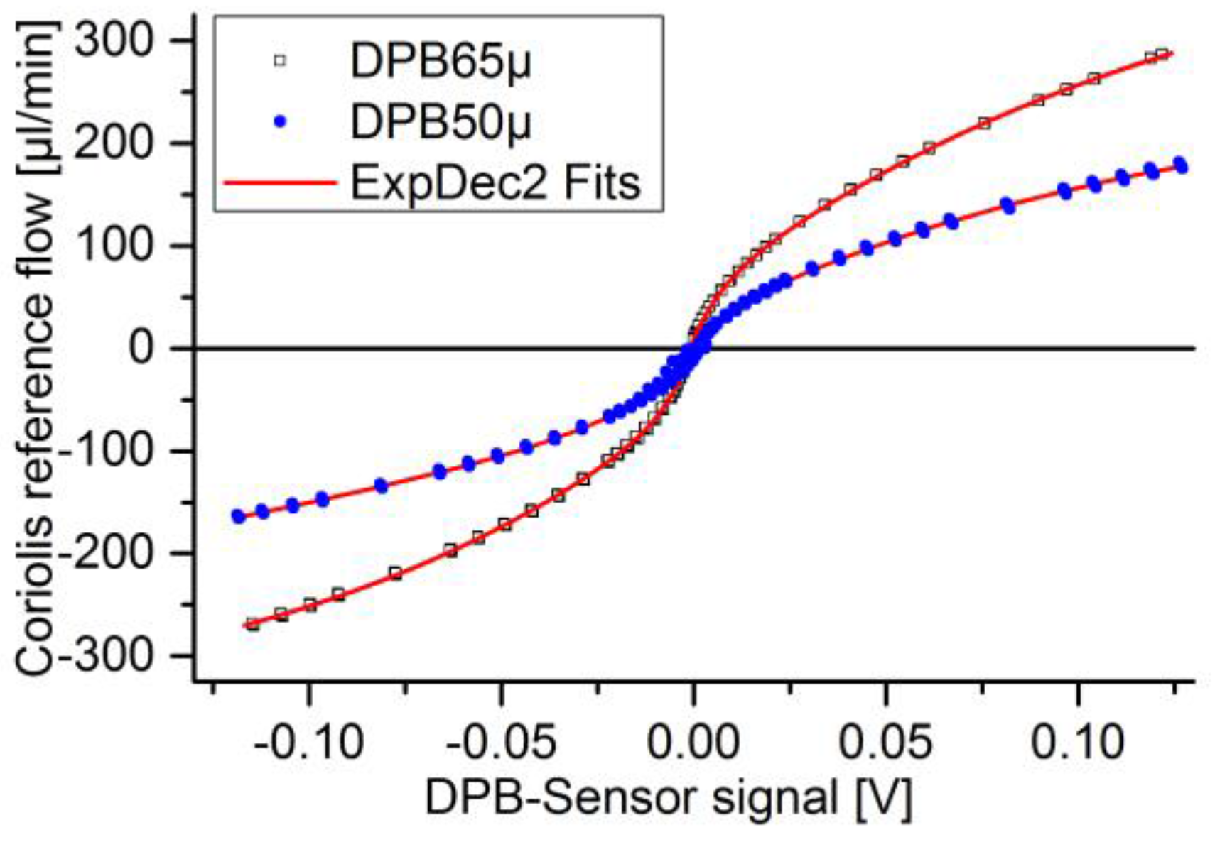
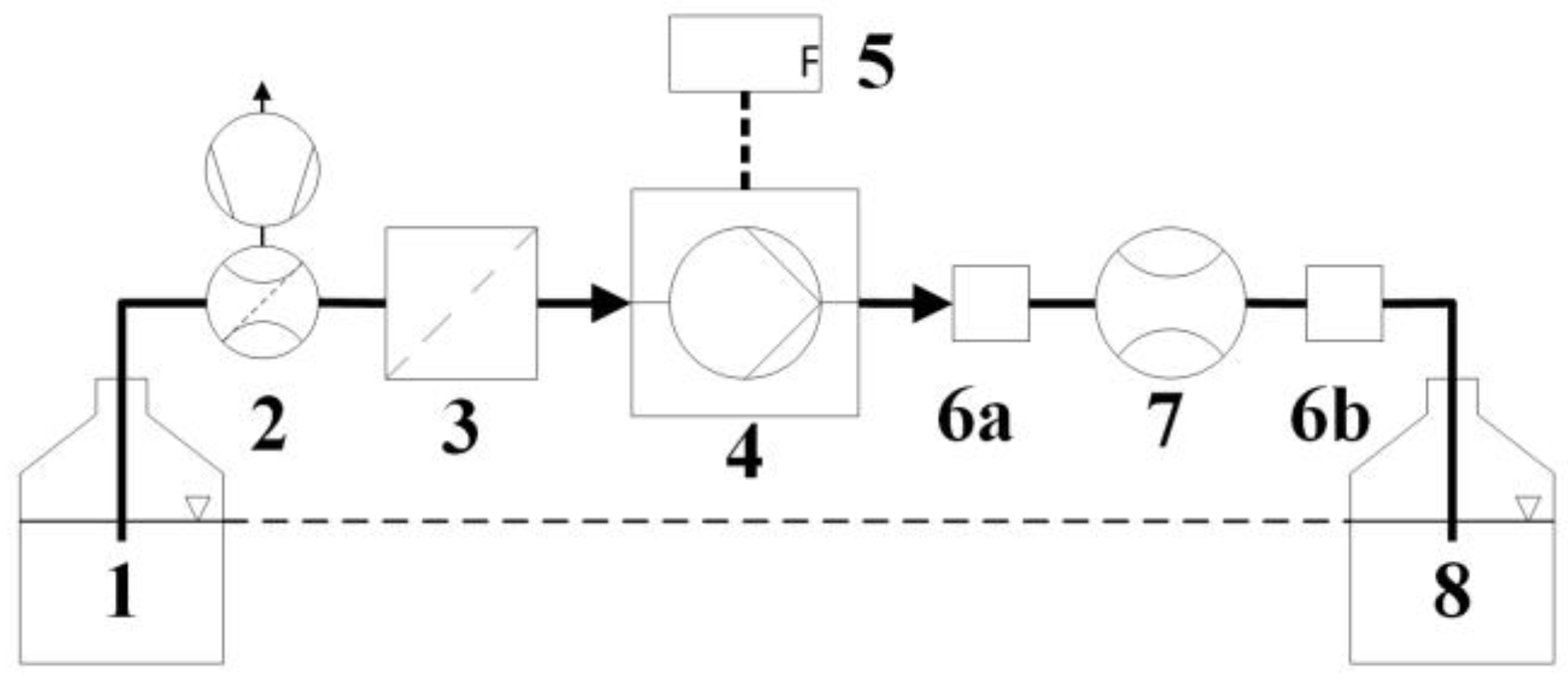
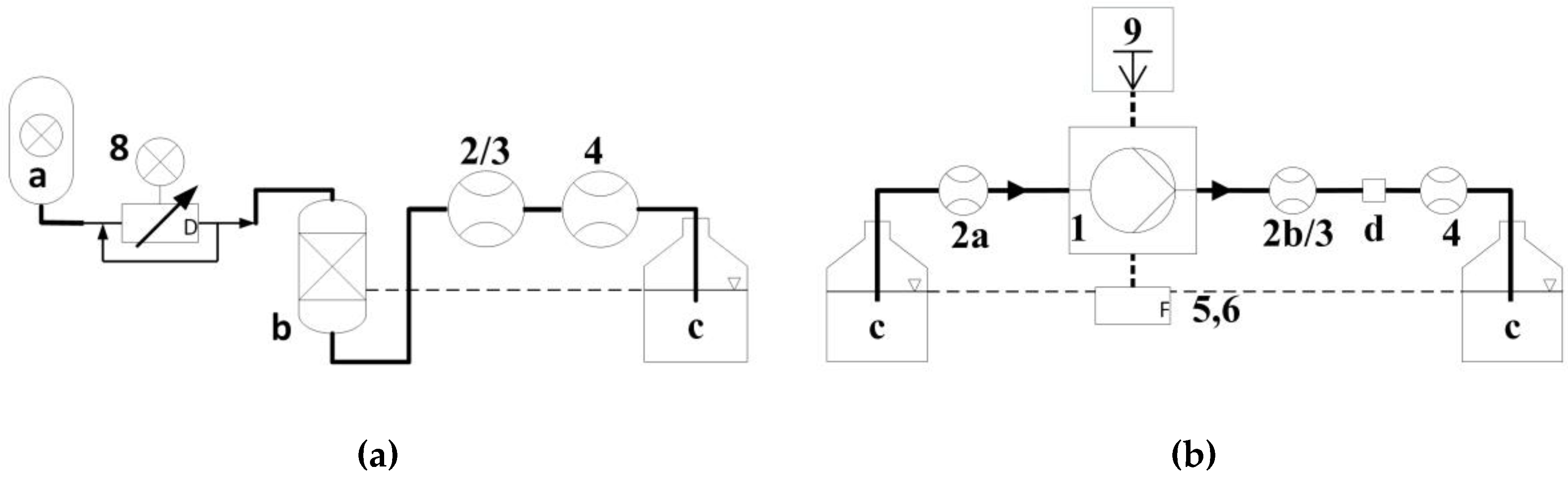
2.2.1. Static Calibration of Flow Sensors
2.2.2. Single Stroke Calibration Method
3. Results
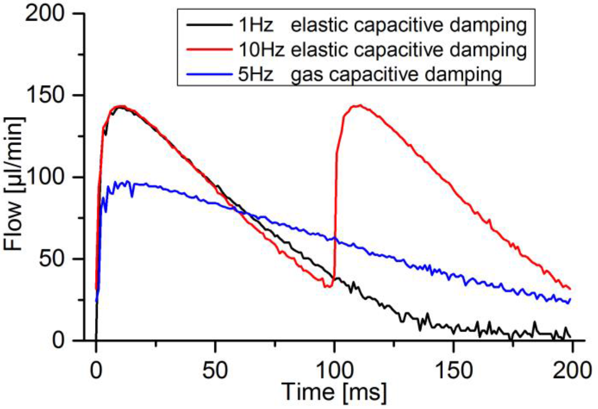
3.1. Capacitive and Resistive Fluidic Damping
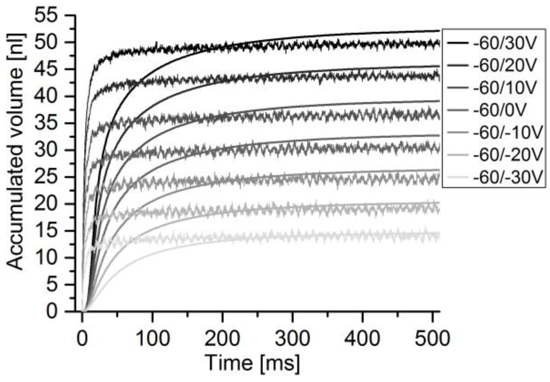
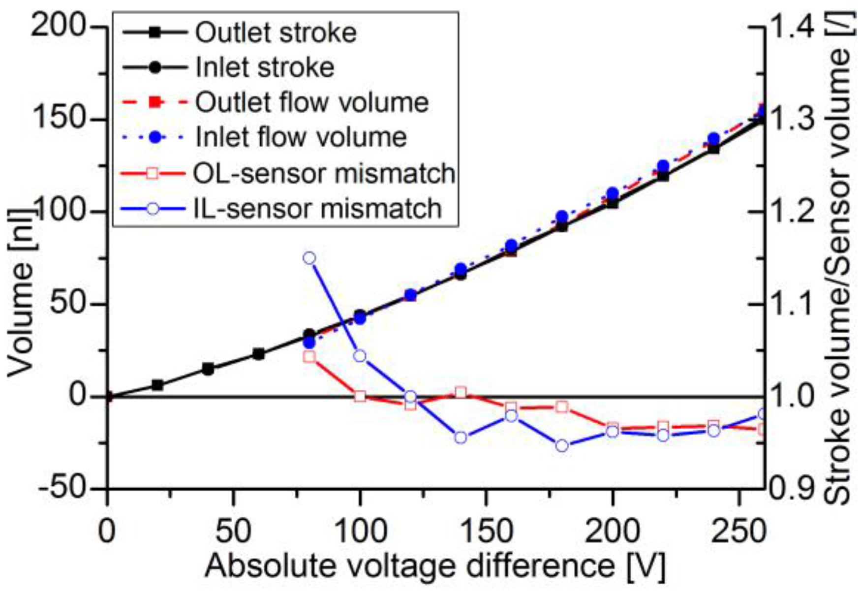
3.2. Transient Single Stroke Measurement
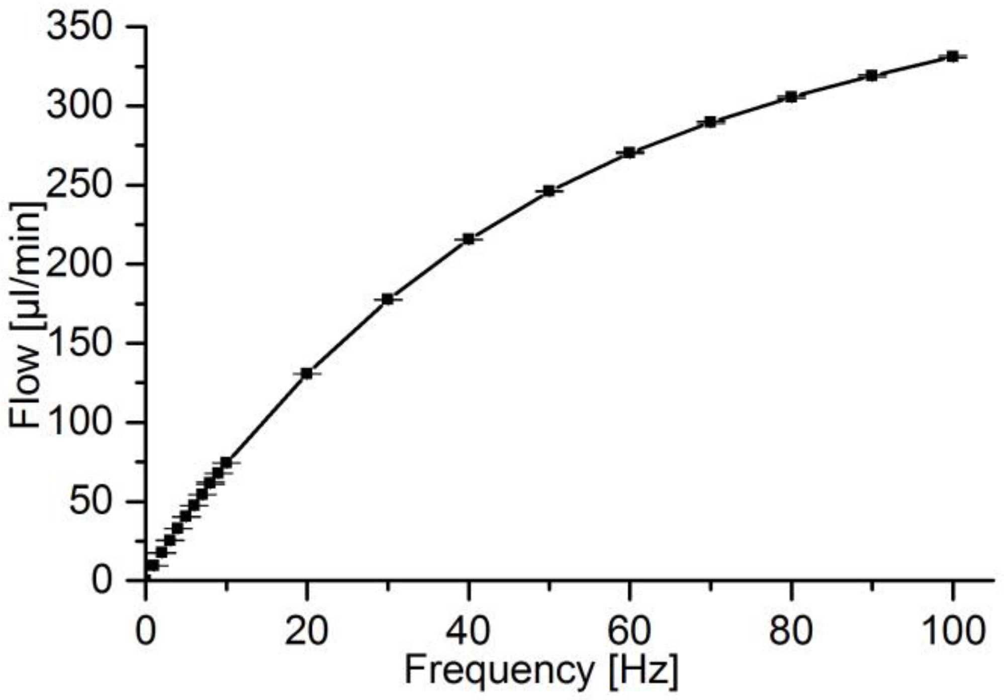
3.3. Single Stroke Based Flow Control Mode
4. Discussion
4.1. Sensor Accuracy at Pulsed Flow
4.2. Flow Control Modes
4.3. Future Investigations
5. Conclusions
Acknowledgments
Author Contributions
Conflicts of Interest
References
- Smits, J.G. Micropompe Piézoélectrique. Patent NL19830002860, 15 August 1984. [Google Scholar]
- Van Lintel, H.; van de Pol, F.; Bouwstra, S. A piezoelectric micropump based on micromachining of silicon. Sens. Actuators 1988, 15, 153–167. [Google Scholar] [CrossRef]
- Smits, J.G. Piezoelectric micropump with three valves working peristaltically. Sens. Actuators A Phys. 1990, 21, 203–206. [Google Scholar] [CrossRef]
- Shoji, S.; Esashi, M. Microflow devices and systems. J. Micromech. Microeng. 1994, 4, 157–171. [Google Scholar] [CrossRef]
- Nguyen, N.-T.; Huang, X.; Chuan, T.K. MEMS-Micropumps: A Review. J. Fluids Eng. 2002, 124, 384. [Google Scholar] [CrossRef]
- Laser, D.J.; Santiago, J.G. A review of micropumps. J. Micromech. Microeng. 2004, 14, R35–R64. [Google Scholar] [CrossRef]
- Woias, P. Micropumps—Past, progress and future prospects. Sens. Actuators B Chem. 2005, 105, 28–38. [Google Scholar] [CrossRef]
- Nisar, A.; Afzulpurkar, N.; Mahaisavariya, B.; Tuantranont, A. MEMS-based micropumps in drug delivery and biomedical applications. Sens. Actuators B Chem. 2008, 130, 917–942. [Google Scholar] [CrossRef]
- Amirouche, F.; Zhou, Y.; Johnson, T. Current micropump technologies and their biomedical applications. Microsyst. Technol. 2009, 15, 647–666. [Google Scholar] [CrossRef]
- Abhari, F.; Jaafar, H.; Yunus, N.A.M. A comprehensive study of micropumps technology. Int. J. Electrochem. Sci. 2012, 7, 9765–9780. [Google Scholar]
- Gravesen, P.; Branebjerg, J.; Jensen, O.S. Microfluidics-a review. J. Micromech. Microeng. 1993, 3, 168. [Google Scholar] [CrossRef]
- Van der Wijngaart, W.; Andersson, H.; Enoksson, P.; Noren, K.; Stemme, G. The first self-priming and bi-directional valve-less diffuser micropump for both liquid and gas. In Proceedings of the IEEE Micro Electro Mechanical Systems (MEMS) 2000, Tucson, AZ, USA, 23–27 January 2000; pp. 674–679. [Google Scholar]
- Richter, M.; Linnemann, R.; Woias, P. Robust design of gas and liquid micropumps. Sens. Actuators A Phys. 1998, 68, 480–486. [Google Scholar] [CrossRef]
- Andersson, H.; van der Wijngaart, W.; Nilsson, P.; Enoksson, P.; Stemme, G. A valve-less diffuser micropump for microfluidic analytical systems. Sens. Actuators B Chem. 2001, 72, 259–265. [Google Scholar] [CrossRef]
- Jenke, C.W.; Muster, T.; Richter, M.; Kutter, C. Particle Tolerance of micro diaphragm pumps with low chamber heights and passive flap valves. In Proceedings of the MikroSystem Technik Kongress 2015, Karlsruhe, Germany, 26–28 October 2015, 1st ed.; VDE VERLAG: Berlin, Germany, 2015; pp. 489–492. [Google Scholar]
- Maillefer, D.; van Lintel, H.; Rey-Mermet, G.; Hirschi, R. A high-performance silicon micropump for an implantable drug delivery system. In Proceedings of the 12th IEEE International Conference on Micro Electro Mechanical Systems, Orlando, FL, USA, 17–21 January 1999; Technical Digest. pp. 541–546. [Google Scholar]
- Zengerle, R.; Richter, M. Simulation of microfluid systems. J. Micromech. Microeng. 1994, 4, 192–204. [Google Scholar] [CrossRef]
- Herz, M.; Horsch, D.; Wachutka, G.; Lueth, T.C.; Richter, M. Design of ideal circular bending actuators for high performance micropumps. Sens. Actuators A Phys. 2010, 163, 231–239. [Google Scholar] [CrossRef]
- Matsumoto, S.; Klein, A.; Schroth, A.; Maeda, R. Micropump based on temperature dependence of liquid viscosity. In Proceedings of the SPIE 3242, Smart Electronics and MEMS, Adelaide, Australia, 14 November 1997; pp. 364–371. [Google Scholar]
- Lupascu, D.C. Fatigue in Ferroelectric Ceramics and Related Issues; Springer: Berlin/Heidelberg, Germany, 2004. [Google Scholar]
- Elwenspoek, M.; Lammerink, T.S.J.; Miyake, R.; Fluitman, J.H.J. Towards integrated microliquid handling systems. J. Micromech. Microeng. 1994, 4, 227–245. [Google Scholar] [CrossRef]
- Nguyen, N.-T.; Meng, A.H.; Black, J.; White, R.M. Integrated flow sensor for in situ measurement and control of acoustic streaming in flexural plate wave micropumps. Sens. Actuators A Phys. 2000, 79, 115–121. [Google Scholar] [CrossRef]
- Woitschach, O.; Sosna, C.; Lang, W.; Uckelmann, J. A new generation of a regulated micropump for medical applications. In Proceedings of the Ninth IEEE Sensors Conference (SENSORS 2010), Waikoloa, HI, USA, 1–4 November 2010; pp. 2472–2477. [Google Scholar]
- Patel, K.; Bartsch, M.; McCrink, M.; Olsen, J.; Mosier, B.; Crocker, R. Electrokinetic pumping of liquid propellants for small satellite microthruster applications. Sens. Actuators B Chem. 2008, 132, 461–470. [Google Scholar] [CrossRef]
- Chen, L.; Liu, Y.; Sun, L.; Qu, D.; Min, J. Intelligent control of Piezoelectric Micropump based on MEMS flow sensor. In Proceedings of the 2010 IEEE/RSJ International Conference on Intelligent Robots and Systems (IROS 2010), Taipei, Taiwan, 18–22 October 2010; pp. 3055–3060. [Google Scholar]
- Fouillet, Y.; Fuchs, O.; Maubert, S.; Cochet, M.; Baleras, F.; Chabrol, C.; David, N.; Campagnolo, R. A Silicon Micropump with On-Chip Flow Meter. Procedia Eng. 2012, 47, 314–317. [Google Scholar] [CrossRef]
- Richter, M.; Wackerle, M.; Woias, P.; Hillerich, B. A novel flow sensor with high time resolution based on differential pressure principle. In Proceedings of the 12th IEEE International Conference on Micro Electro Mechanical Systems, Orlando, FL, USA, 17–21 January 1999; Technical Digest. pp. 118–123. [Google Scholar]
- Huang, P.-C.; Wang, M.-H.; Chen, M.-K.; Jang, L.-S. Experimental analysis of time-phase-shift flow sensing based on a piezoelectric peristaltic micropump. J. Phys. D Appl. Phys. 2016, 49, 175402. [Google Scholar] [CrossRef]
- Wang, M.; Chen, J. A high-precision gravity intravenous infusion rate meter using CMUT arrays. In Proceedings of the 2009 IEEE International Ultrasonics Symposium, Rome, Italy, 20–23 September 2009; pp. 1355–1358. [Google Scholar]
- Ni, J.; Wang, B.; Chang, S.; Lin, Q. An integrated planar magnetic micropump. Microelectron. Eng. 2014, 117, 35–40. [Google Scholar] [CrossRef]
- Al-Halhouli, A.T.; Demming, S.; Dietzel, A.; Büttgenbach, S. Design, Fabrication, and Characterization of a Continuous Flow Micropump System. J. Therm. Sci. Eng. Appl. 2016, 8, 21006. [Google Scholar] [CrossRef]
- Kibler, S. Feedback controlled microdosing system for nanoliter per second dosing rates using a capacitive phase boundary time-of-flight flow sensor. Proceedings of 2nd International Conference on MicroFluidic Handling Systems-MfHS, Freiburg, Germany, 8–10 October 2014. [Google Scholar]
- Richter, M.; Wackerle, M.; Kibler, S.; Biehl, M.; Koch, T.; Müller, C.; Zeiter, O.; Nuffer, J.; Halter, R. Miniaturized drug delivery system TUDOS with accurate metering of microliter volumes. In Proceedings of the AMA Conference 2013, Nürnberg, Germany, 14–16 May 2013; AMA-Service-GmbH: Wunstorf, Germany, 2013; pp. 420–425. [Google Scholar]
- Böhm, S.; Timmer, B.; Olthuis, W.; Bergveld, P. A closed-loop controlled electrochemically actuated micro-dosing system. J. Micromech. Microeng. 2000, 10, 498–504. [Google Scholar] [CrossRef]
- Haneveld, J.; Lammerink, T.; Dijkstra, M.; Droogendijk, H.; de Boer, M.J.; Wiegerink, R.J. Highly sensitive micro coriolis mass flow sensor. In Proceedings of the 21st IEEE International Conference on Micro Electro Mechanical Systems, Tucson, AZ, USA, 13–17 January 2008; pp. 920–923. [Google Scholar]
- Dinh, T.X.; van Dau, T.; Sugiyama, S.; Pham, P.H. Fluidic device with pumping and sensing functions for precise flow control. Sens. Actuators B Chem. 2010, 150, 819–824. [Google Scholar] [CrossRef]
- Gass, V.; van der Schoot, B.H.; Jeanneret, S.; de Rooij, N.F. Integrated flow-regulated silicon micropump. Sens. Actuators A Phys. 1994, 43, 335–338. [Google Scholar] [CrossRef]
- Lien, V.; Vollmer, F. Microfluidic flow rate detection based on integrated optical fiber cantilever. Lab Chip 2007, 7, 1352–1356. [Google Scholar] [CrossRef] [PubMed]
- Fuchs, O.; Fouillet, Y.; Maubert, S.; Cochet, M.; Chabrol, C.; David, N.; Médal, X.; Campagnolo, R. A novel volumetric silicon micropump with integrated sensors. Microelectron. Eng. 2012, 97, 375–378. [Google Scholar] [CrossRef]
- Dumont-Fillon, D.; Tahriou, H.; Conan, C.; Chappel, E. Insulin Micropump with Embedded Pressure Sensors for Failure Detection and Delivery of Accurate Monitoring. Micromachines 2014, 5, 1161–1172. [Google Scholar] [CrossRef]
- Zhang, Z.; Kan, J.; Cheng, G.; Wang, H.; Jiang, Y. A piezoelectric micropump with an integrated sensor based on space-division multiplexing. Sens. Actuators A Phys. 2013, 203, 29–36. [Google Scholar] [CrossRef]
- Zengerle, R.; Geiger, W.; Richter, M.; Ulrich, J.; Kluge, S.; Richter, A. Transient measurements on miniaturized diaphragm pumps in microfluid systems. Sens. Actuators A Phys. 1995, 47, 557–561. [Google Scholar] [CrossRef]
- Sensirion. LPG10 Liquid Flow Sensor (Preliminary Datasheet). Available online: https://www.sensirion.com/fileadmin/user_upload/customers/sensirion/Dokumente/4_Liquid_Flow_Meters/Sensirion_Liquid_Flow_Meters_LPG10–0150_0500_Preliminary_Datasheet_V4.pdf (accessed on 23 December 2016).
- Ashauer, M.; Glosch, H.; Hedrich, F.; Hey, N.; Sandmaier, H.; Lang, W. Thermal flow sensor for liquids and gases based on combinations of two principles. Sens. Actuators A Phys. 1999, 73, 7–13. [Google Scholar] [CrossRef]
- Bronkhorst. Mini CORI-FLOW Datasheet M12–M14. Available online: http://www.bronkhorst.com/files/coriolis/downloads/brochures-en/mini_coriflow.pdf (accessed on 20 December 2016).
- Sartorius. Cubis MSA225S Datasheet. Available online: https://www.sartorius.com/_ui/images/h10/h2c/8836071489566.pdf (accessed on 23 December 2016).
- Richter, M. Proportioner. Patent 22 April 1998. [Google Scholar]
- Kuo, J.T.W.; Yu, L.; Meng, E. Micromachined Thermal Flow Sensors—A Review. Micromachines 2012, 3, 550–573. [Google Scholar] [CrossRef]
- Lammerink, T.S.; Tas, N.R.; Elwenspoek, M.; Fluitman, J.H. Micro-liquid flow sensor. Sens. Actuators A Phys. 1993, 37–38, 45–50. [Google Scholar] [CrossRef]
- Dijkstra, M.; de Boer, M.J.; Berenschot, J.W.; Lammerink, T.; Wiegerink, R.J.; Elwenspoek, M. Miniaturized thermal flow sensor with planar-integrated sensor structures on semicircular surface channels. Sens. Actuators A Phys. 2008, 143, 1–6. [Google Scholar] [CrossRef]
- Richter, M.; Prak, A.; Naundorf, J.; Eberl, M.; Leeuwis, H.; Woias, P.; Steckenborn, A. A chemical microanalysis system as a microfluid system demonstrator. In Proceedings of the Transducers’97 9th International Conference on Solid-State Sensors and Actuators, Chicago, IL, USA, 16–19 June 1997; pp. 303–306. [Google Scholar]
- Nguyen, N.T.; Schubert, S.; Richter, S.; Dötzel, W. Hybrid-assembled micro dosing system using silicon-based micropump/valve and mass flow sensor. Sens. Actuators A Phys. 1998, 69, 85–91. [Google Scholar] [CrossRef]
- Zengerle, R.; Leitner, M.; Kluge, S.; Richter, A. Carbon dioxide priming of micro liquid systems. In Proceedings of the MEMS ‘95, IEEE Micro Electro Mechanical Systems, Amsterdam, The Netherlands, 29 January–2 February 1995; pp. 340–343. [Google Scholar]
- Richter, M.; Wackerle, M.; Kibler, S.; Biehl, M.; Koch, T.; Müller, C.; Zeiter, O.; Nuffer4, J.; Halter, R. Miniaturized drug delivery system TUDOS with accurate metering of microliter volumes. In Proceedings of the AMA Conference 2013, Nürnberg, Germany, 14–16 May 2013; AMA-Service-GmbH: Wunstorf, Germany; pp. 420–425. [Google Scholar]
- Jenke, C.W.; Kibler, S.; Gao, Y.; Hollot, A.; Neuhann, T.; Kirchhof, B.; Montag, B.; Geiger, M.; Neitzel, J.; Kutter, C.; et al. Optimization of a Piezoelectric Micropump Actuator for Medical Application in Glaucoma and Phthisis Therapy. In Proceedings of the 14th International Conference on New Actuators, Bremen, Germany, 23–25 June 2014; Borgmann, H., Ed.; Messe Bremen, WFB Wirtschaftsförderung: Bremen, Geramny, 2014; pp. 165–168. [Google Scholar]
- Richter, M.; Wackerle, M.; Herz, M. Bending-Transducer. Patent WO002011107162, 5 March 2010. [Google Scholar]


| Sensor Principle | Measurement Velocity |
|---|---|
| Optical/capacitive flank monitoring | 0.4 ms [42] |
| Differential pressure based | <1 ms [27] |
| Thermal calorimeter | 40 ms [43] |
| Thermal TOF (time-of-flight) | 6–25 ms [44] |
| Coriolis | 50–200 ms [45] |
| Gravimetric balance | <2 s [46] |
| Materials and Equipment | Manufacturer and Model |
|---|---|
| Silicon micropumps | Fraunhofer EMFT [54,55] |
| Differential pressure based (DPB) flow sensor | Fraunhofer EMFT [27] |
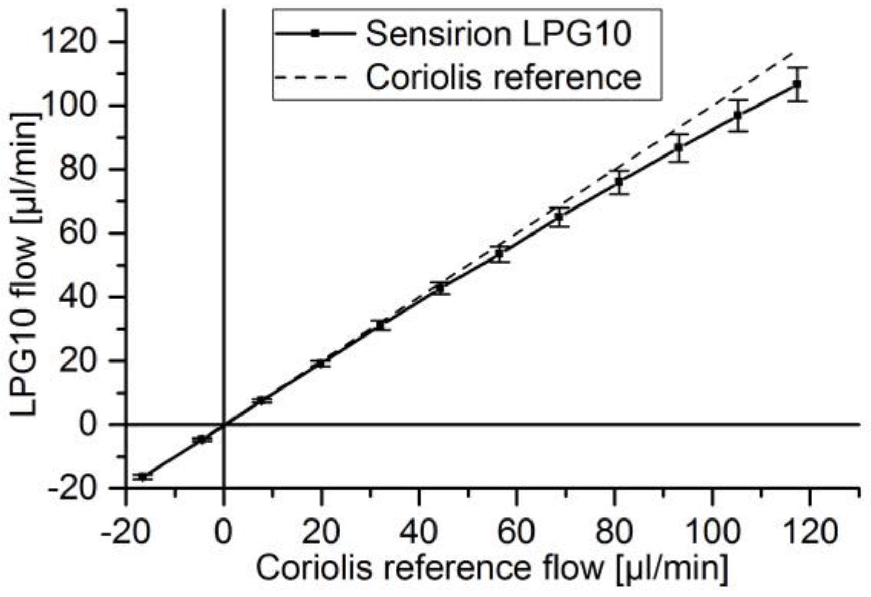
| Thermal flow sensor | Sensirion LPG10-0500 |
| Coriolis mass flow meter | Bronkhorst miniCORI-Flow |
| Gravimetric balance | Sartorius 225S |
| Frequency generator | Agilent 33120A |
| High voltage amplifier | Piezomechanik SVR 150/3 |
| Pressure controller | Mensor CPC3000 |
| Surface topography measurement | FRT 300 μm sensor |
| Analog readout device | NI I/O-Box 6211 |
| Actuator | Diaphragm Thickness | Diaphragm Diameter | Piezo Thickness | Piezo Diameter | Piezo Type | Pump Chamber Height |
|---|---|---|---|---|---|---|
| 40 μm | 6.6 mm | 150 μm | 5.6 mm | PIC255 | 3 μm | |
| Valves | Flap length | Flap width | Flap thickness | Valve seat length (cubic) | Seal lip width | |
| 800 μm | 400 μm | 15 μm | 3 00 μm | 6 μm |
| Label | Pressure Range | Repeatability and Hysteresis | Nozzle Diameter | Diffuser Diameter | Max. Nozzle Flow | Max. Diffuser Flow |
|---|---|---|---|---|---|---|
| DPB65μ | 5 psi = 34.5 kPa at 110 mV | ±52 Pa or ±0.17 mV | 65 μm | 60 μm | 270 μL/min | 260 μL/min |
| DPB50μ | 5 psi = 34.5 kPa at 110 mV | ±52 Pa or ±0.17 mV | 50 μm | 45 μm | 165 μL/min | 158 μL/min |
| Method | Measurement of |
|---|---|
| (a) Static calibration of flow sensors | Static reference flow vs. sensor voltage |
| (b) Dynamic calibration of flow sensors | Stroke volume vs. sensor voltage vs. average reference flow |
© 2017 by the authors. Licensee MDPI, Basel, Switzerland. This article is an open access article distributed under the terms and conditions of the Creative Commons Attribution (CC BY) license (http://creativecommons.org/licenses/by/4.0/).
Share and Cite
Jenke, C.; Pallejà Rubio, J.; Kibler, S.; Häfner, J.; Richter, M.; Kutter, C. The Combination of Micro Diaphragm Pumps and Flow Sensors for Single Stroke Based Liquid Flow Control. Sensors 2017, 17, 755. https://doi.org/10.3390/s17040755
Jenke C, Pallejà Rubio J, Kibler S, Häfner J, Richter M, Kutter C. The Combination of Micro Diaphragm Pumps and Flow Sensors for Single Stroke Based Liquid Flow Control. Sensors. 2017; 17(4):755. https://doi.org/10.3390/s17040755
Chicago/Turabian StyleJenke, Christoph, Jaume Pallejà Rubio, Sebastian Kibler, Johannes Häfner, Martin Richter, and Christoph Kutter. 2017. "The Combination of Micro Diaphragm Pumps and Flow Sensors for Single Stroke Based Liquid Flow Control" Sensors 17, no. 4: 755. https://doi.org/10.3390/s17040755
APA StyleJenke, C., Pallejà Rubio, J., Kibler, S., Häfner, J., Richter, M., & Kutter, C. (2017). The Combination of Micro Diaphragm Pumps and Flow Sensors for Single Stroke Based Liquid Flow Control. Sensors, 17(4), 755. https://doi.org/10.3390/s17040755