
Patient Posture Monitoring System Based on Flexible Sensors


Abstract
:1. Introduction
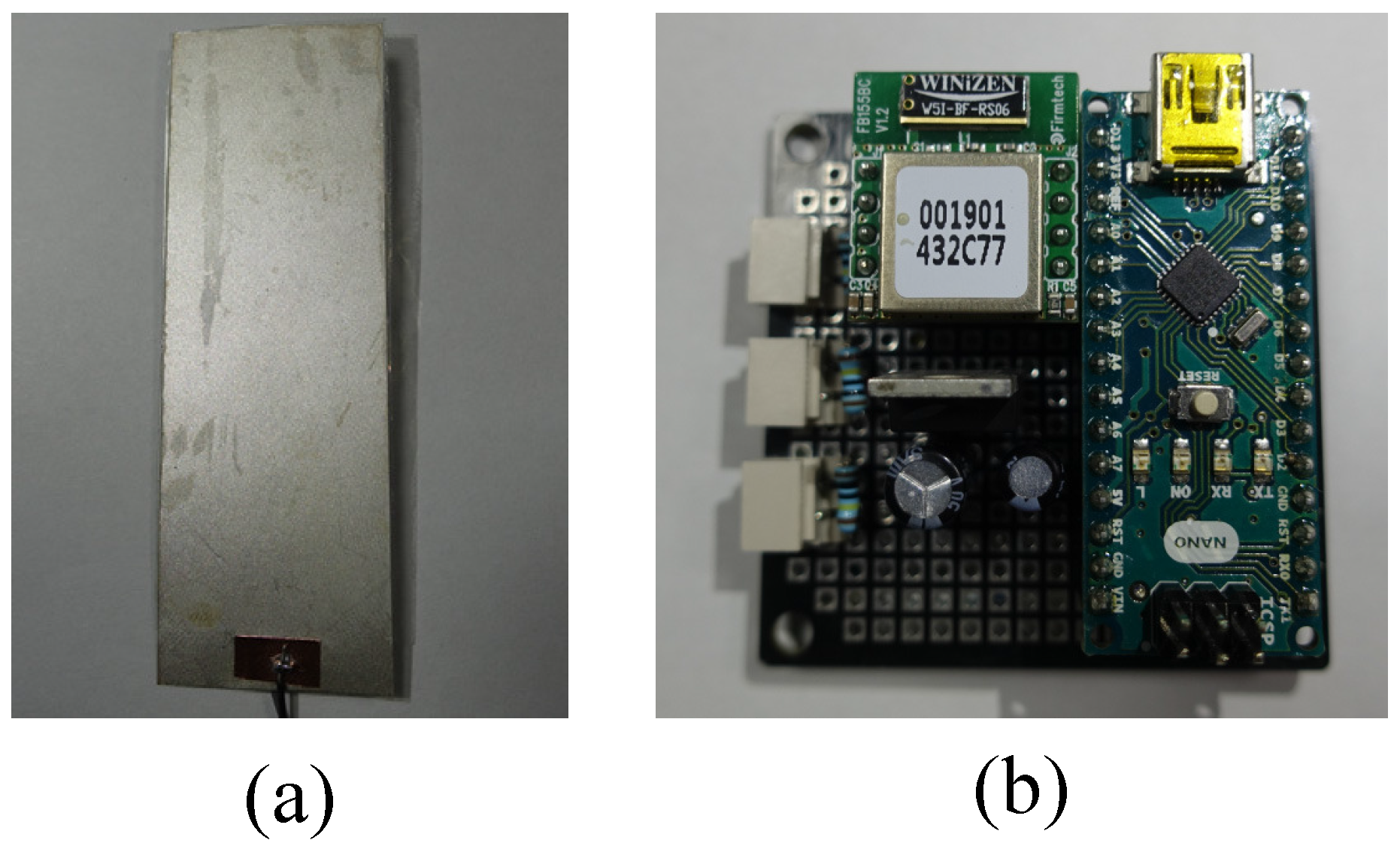
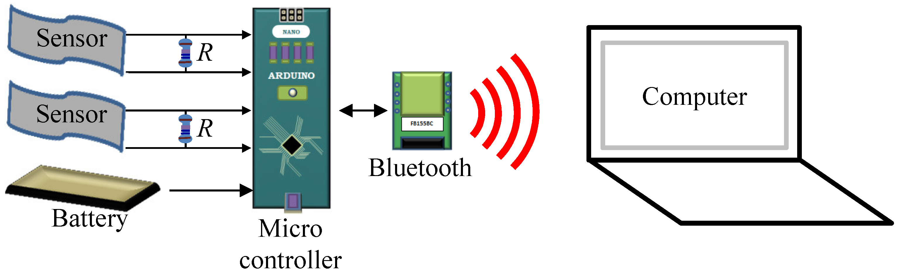
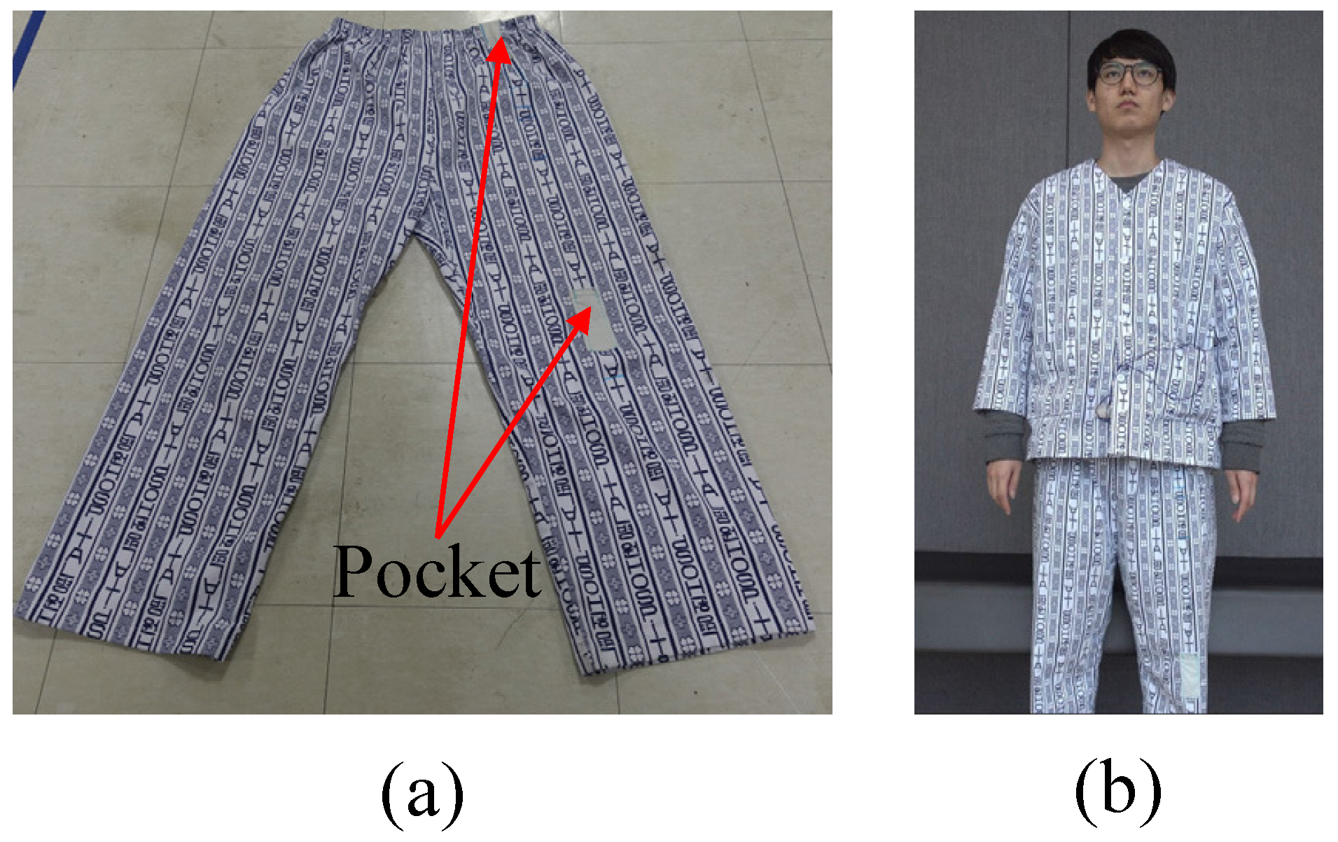
2. System Setup
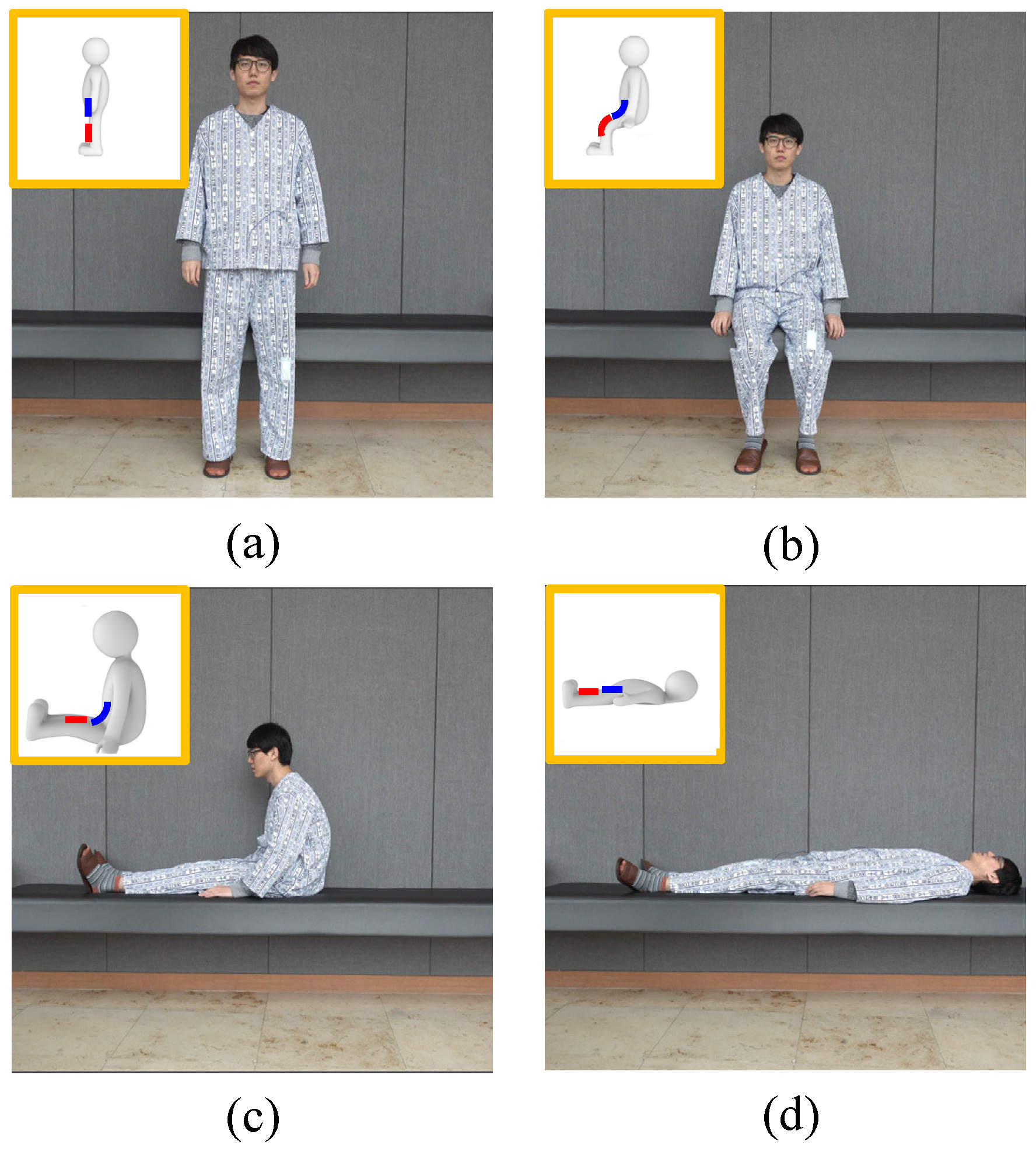
3. Patient Posture and Sensor Output
4. Decision Method
- Step 1:
- The offsets of the digitalized sensor outputs in Figure 5 have removed. We use the average value of 9000 in the dataset as the offset. It is mathematically described aswhere is the digitalized sensor output, and is the value without the offset.
- Step 2:
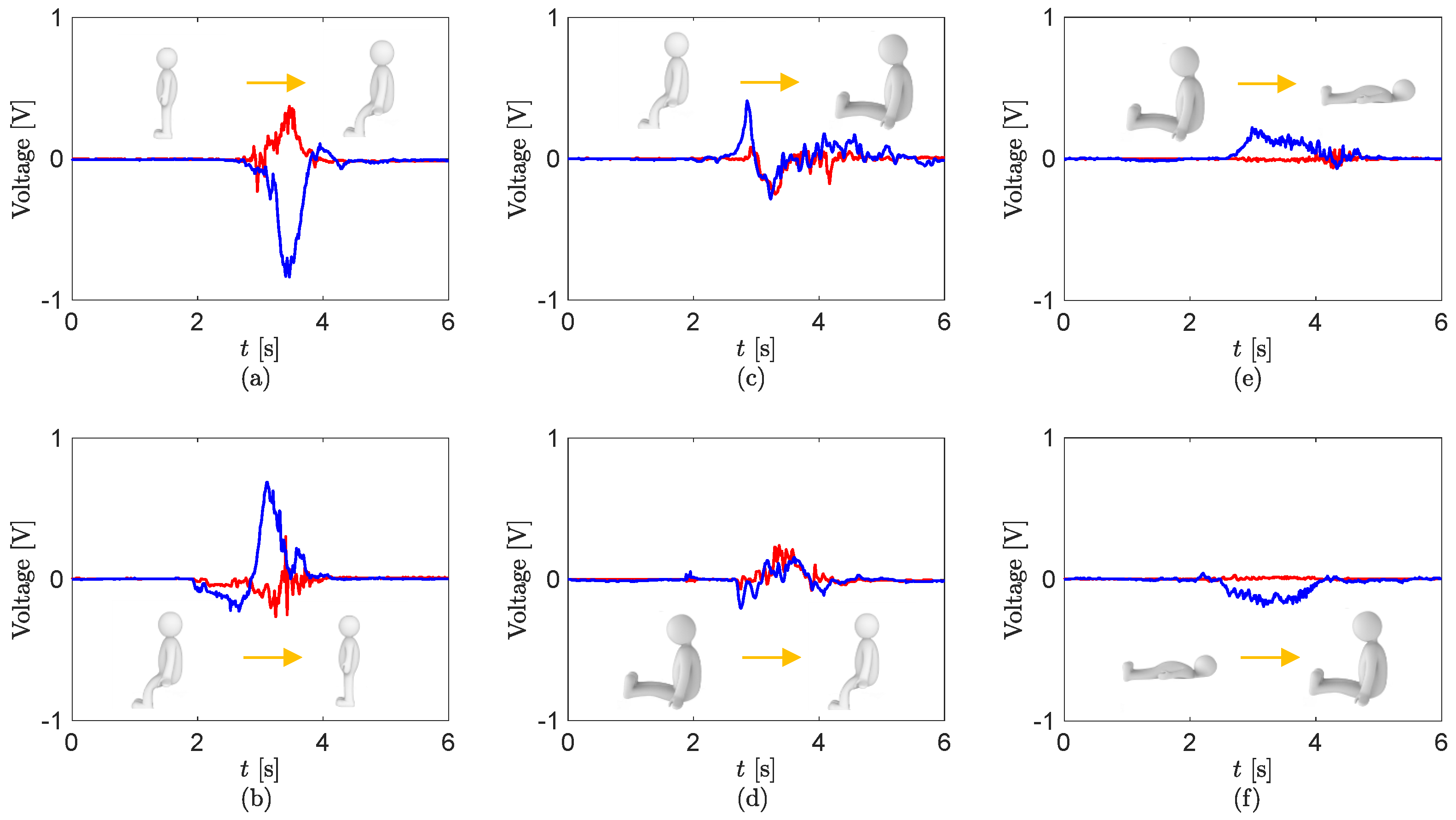
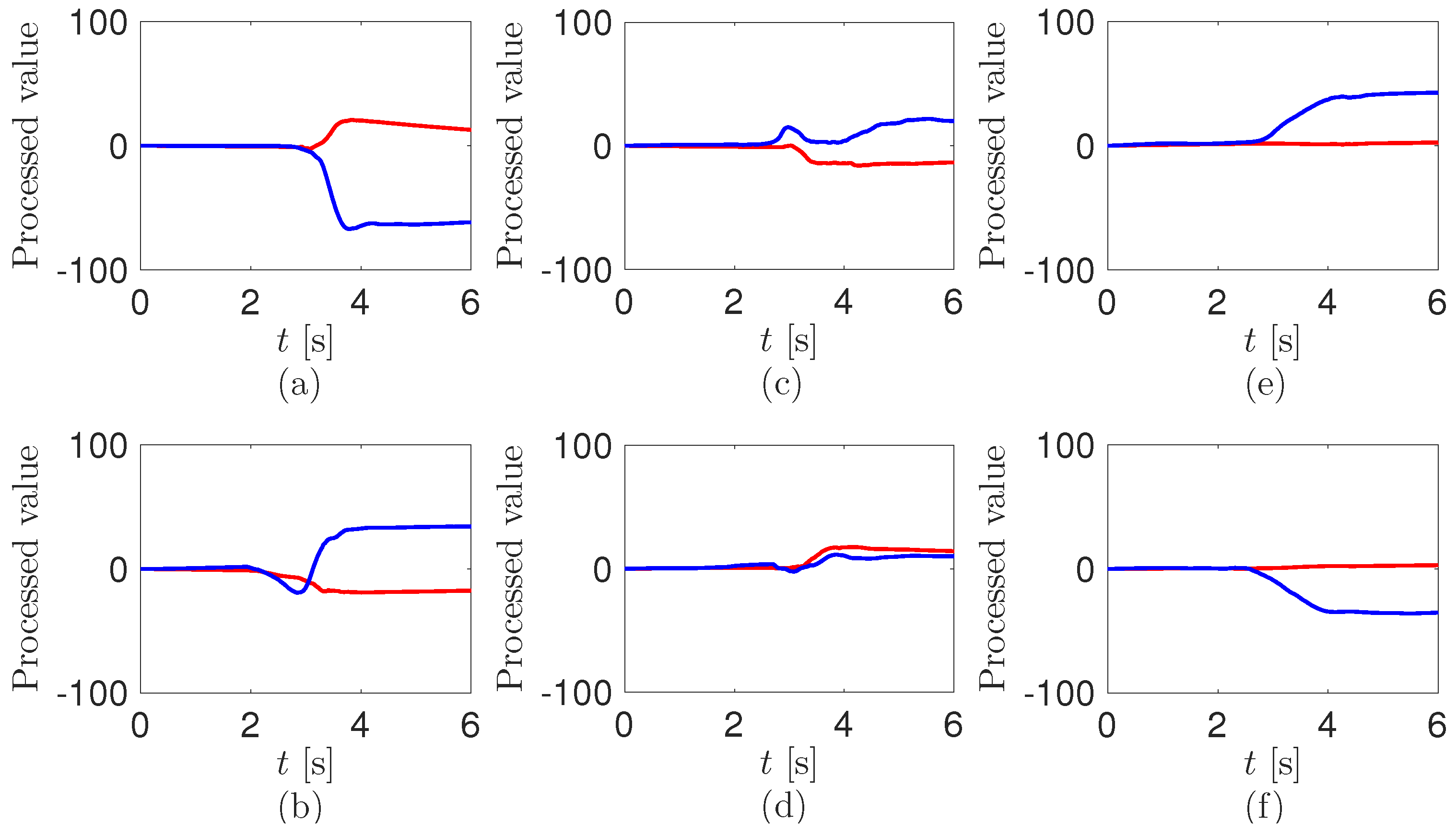
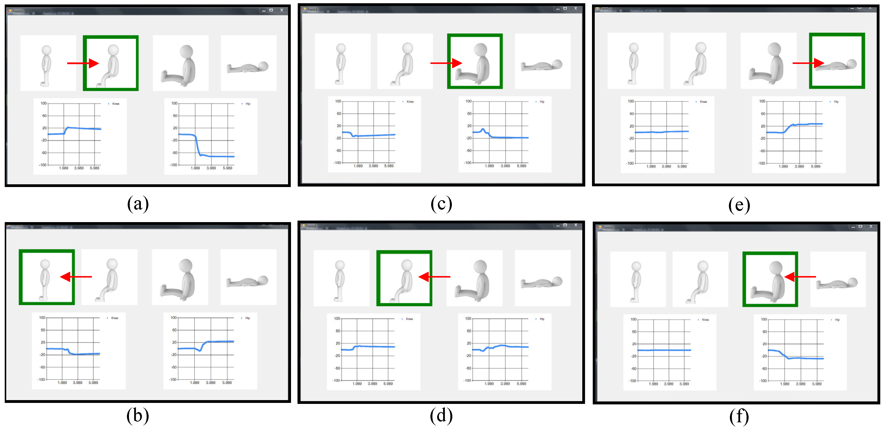
- The values after removing the offset are integrated as the timewhere is the integrated value and is the time interval.The processed values from the sensor outputs in Figure 5 are shown in Figure 6. In Figure 6a, the positive knee value and the negative hip value are saturated. Further, they have the opposite values in Figure 6b. This is due to the characteristics of the piezoelectric sensor outputs, of which raw voltage and integration at a load resistance may be proportional to the angular velocity and angle, respectively [52]. The profiles of the processed values from the knee in Figure 6c,d are the same as in Figure 6a,b, respectively. The values at the hip in Figure 6c,d are oscillated and converged to much smaller ones than in Figure 6a,b. In Figure 6e,f, while the values at the knee are not moving, the ones at the hip are saturated to the larger positive and negative values, respectively. The converged values at the hip are slightly more decreased than in Figure 6a,b. Reasons for the decreases may be ascribed to the changes of the bending of the pants during the turning motion between the sitting position and sitting knee extension position.
- Step 3:
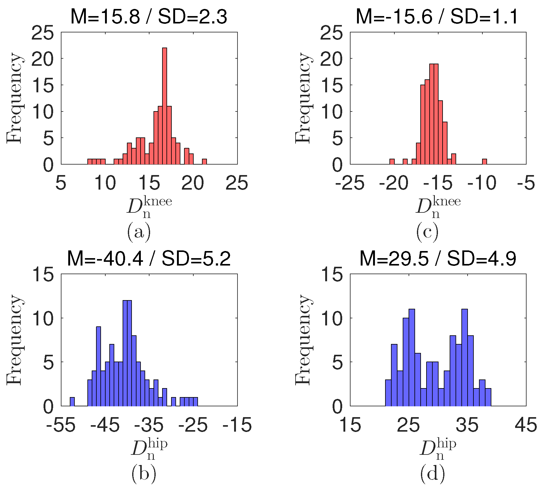
- We use a rule-based algorithm [53,54] to decide the postures of the patient wearing the cloth with the sensors. Specifically, the bending and extension of the knee and hip at of the sensors in the patient’s pants can be detected from the processed values in Figure 6. We compare the difference between the current processed value and the previous one before 200 counts; that is,where and are the differences at the knee and hip, respectively. and are the decision values at the knee and hip, respectively.The decision values for the detection are selected as and by preliminary tests with each having 100 repetitions between the standing and the sitting positions; see the histogram and statistical data in Figure 7. The decision values are / and / at the knee and hip during the joint bending/extension, respectively. Notably, the decision values and signs at the knee and hip are different. The value gap can be attributed to the effect of each joint structure, which results in different mechanical displacement of the sensor. The variations under the decision values expect that the bending and extension of the joints are smaller than . The opposite sign results from the different bending direction at the knee and hip. The decision values may differ as the body structure of the patient varies.
- Step 4:
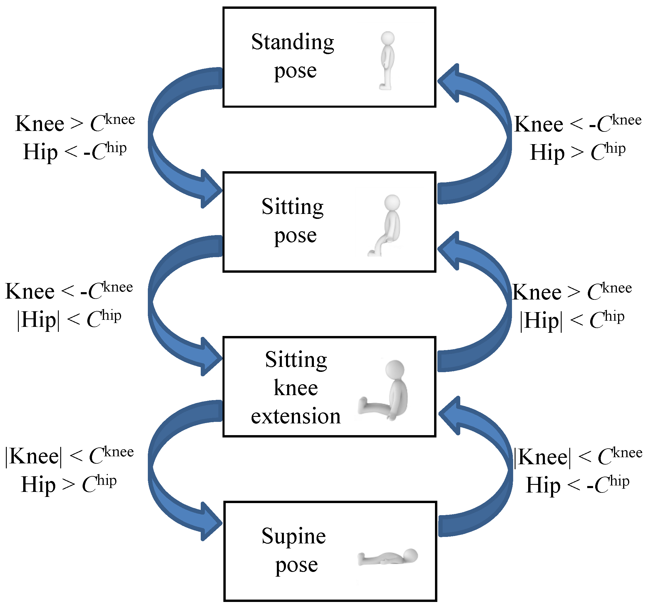
- By using the previous posture state and the decisions in Step 3, we predict the current position of the patient; that is,where is the posture state and is the decision function.Figure 8 displays the flow chart to decide the position of the patient. For example, when is under and is higher than at the sitting pose, the transferred pose is standing. In the program, we use the standing position as the initial state.
5. System Operation
6. Conclusions
Supplementary Materials
Acknowledgments
Author Contributions
Conflicts of Interest
References
- Pawar, P.; Jones, V.; Van Beijnum, B.F.; Hermens, H. A framework for the comparison of mobile patient monitoring systems. J. Biomed. Inf. 2012, 45, 544–556. [Google Scholar] [CrossRef] [PubMed]
- Liang, T.; Yuan, Y.J. Wearable medical monitoring systems based on wireless networks: A review. IEEE Sens. J. 2016, 16, 8186–8199. [Google Scholar] [CrossRef]
- Peetoom, K.K.B.; Lexis, M.A.S.; Joore, M.; Dirksen, C.D.; De Witte, L.P. Literature review on monitoring technologies and their outcomes in independently living elderly people. Disabil. Rehabil. Assist. Technol. 2015, 10, 271–294. [Google Scholar] [CrossRef] [PubMed]
- Chen, S.; Kao, T.; Chan, C.; Huang, C.; Chiang, C.; Lai, C.; Tung, T.; Wang, P. A reliable transmission protocol for zigbee-based wireless patient monitoring. IEEE Trans. Inf. Technol. Biomed. 2012, 16, 6–16. [Google Scholar] [CrossRef] [PubMed]
- Baig, M.M.; Gholamhosseini, H. Smart health monitoring systems: An overview of design and modeling. J. Med. Syst. 2013, 37, 1–14. [Google Scholar] [CrossRef] [PubMed]
- Varshney, U. Pervasive healthcare and wireless health monitoring. Mob. Netw. Appl. 2007, 12, 113–127. [Google Scholar] [CrossRef]
- Sneha, S.; Varshney, U. Enabling ubiquitous patient monitoring: Model, decision protocols, opportunities and challenges. Decis. Support Syst. 2009, 46, 606–619. [Google Scholar] [CrossRef]
- Sathyanarayana, S.; Satzoda, R.K.; Sathyanarayana, S.; Thambipillai, S. Vision-based patient monitoring: A comprehensive review of algorithms and technologies. J. Ambient Intell. Humaniz. Comput. 2015. [Google Scholar] [CrossRef]
- Yu, M.; Rhuma, A.; Naqvi, S.M.; Wang, L.; Chambers, J. A posture recognition-based fall detection system for monitoring an elderly person in a smart home environment. IEEE Trans. Inf. Technol. Biomed. 2012, 16, 1274–1286. [Google Scholar] [PubMed]
- Mubashir, M.; Shao, L.; Seed, L. A survey on fall detection: Principles and approaches. Neurocomputing 2013, 100, 144–152. [Google Scholar] [CrossRef]
- Malakuti, K.; Albu, A.B. Towards an intelligent bed sensor: Non-intrusive monitoring of sleep irregularities with computer vision techniques. In Proceedings of the 20th International Conference on Pattern Recognition, Istanbul, Turkey, 23–26 August 2010; pp. 4004–4007.
- Chen, L.C.; Chen, K.; Hung, Y. A sleep monitoring system based on audio, video and depth information for detecting sleep events. In Proceedings of the IEEE International Conference on Multimedia and Expo, Chengdu, China, 14–18 July 2014; pp. 1–6.
- Kuo, Y.; Lee, J.; Chung, P. A visual context-awareness-based sleeping-respiration measurement system. IEEE Trans. Inf. Technol. Biomed. 2010, 14, 255–265. [Google Scholar] [PubMed]
- Martinez, M.; Stiefelhagen, R. Breath rate monitoring during sleep using near-IR imagery and PCA. In Proceedings of the 21st International Conference on Pattern Recognition, Tsukuba, Japan, 11–15 November 2012; pp. 3472–3475.
- Cohn, J.F.; Kruez, T.S.; Matthews, I.; Yang, Y.; Nguyen, M.H.; Padilla, M.T.; Zhou, F.; De la Torre, F. Detecting depression from facial actions and vocal prosody. In Proceedings of the 3rd International Conference on Affective Computing and Intelligent Interaction and Workshops, Amsterdam, The Netherlands, 10–12 September 2009; pp. 1–7.
- Alghowinem, S.; Goecke, R.; Wagner, M.; Parker, G.; Breakspear, M. Eye movement analysis for depression detection. In Proceedings of the IEEE International Conference on Image Processing, Melbourne, Australia, 15–18 September 2013; pp. 4220–4224.
- Poh, M.; McDuff, D.J.; Picard, R.W. Non-contact, automated cardiac pulse measurements using video imaging and blind source separation. Opt. Express 2010, 18, 10762–10774. [Google Scholar] [CrossRef] [PubMed]
- Kwon, S.; Kim, H.; Park, K.S. Validation of heart rate extraction using video imaging on a built-in camera system of a smartphone. In Proceedings of the Annual International Conference of the IEEE Engineering in Medicine and Biology Society, San Diego, CA, USA, 28 August–1 September 2012; pp. 2174–2177.
- Brulin, D.; Benezeth, Y.; Courtial, E. Posture recognition based on fuzzy logic for home monitoring of the elderly. IEEE Trans. Inf. Technol. Biomed. 2012, 16, 974–982. [Google Scholar] [CrossRef] [PubMed]
- Obdržálek, S.; Kurillo, G.; Ofli, F.; Bajcsy, R.; Seto, E.; Jimison, H.; Pavel, M. Accuracy and robustness of Kinect pose estimation in the context of coaching of elderly population. In Proceedings of the Annual International Conference of the IEEE Engineering in Medicine and Biology Society, San Diego, CA, USA, 28 August–1 September 2012; pp. 1188–1193.
- Igual, R.; Medrano, C.; Plaza, I. Challenges, issues and trends in fall detection systems. Biomed. Eng. Online 2013, 12, 1. [Google Scholar] [CrossRef] [PubMed]
- Bulling, A.; Blanke, U.; Schiele, B. A tutorial on human activity recognition using body-worn inertial sensors. ACM Comput. Surv. 2014, 46, 33. [Google Scholar] [CrossRef]
- Miyazaki, S. Long-term unrestrained measurement of stride length and walking velocity utilizing a piezoelectric gyroscope. IEEE Trans. Biomed. Eng. 1997, 44, 753–759. [Google Scholar] [CrossRef] [PubMed]
- Morris, S.J.; Paradiso, J.A. A compact wearable sensor package for clinical gait monitoring. Offspring 2003, 1, 7–15. [Google Scholar]
- Zhang, R.; Hoflinger, F.; Reindl, L. Inertial sensor based indoor localization and monitoring system for emergency responders. IEEE Sens. J. 2013, 13, 838–848. [Google Scholar] [CrossRef]
- Ayrulu-Erdem, B.; Barshan, B. Leg motion classification with artificial neural networks using wavelet-based features of gyroscope signals. Sensors 2011, 11, 1721–1743. [Google Scholar] [CrossRef] [PubMed]
- Regterschot, G.R.H.; Folkersma, M.; Zhang, W.; Baldus, H.; Stevens, M.; Zijlstra, W. Sensitivity of sensor-based sit-to-stand peak power to the effects of training leg strength, leg power and balance in older adults. Gait Posture 2014, 39, 303–307. [Google Scholar] [CrossRef] [PubMed]
- Regterschot, G.R.H.; Zhang, W.; Baldus, H.; Stevens, M.; Zijlstra, W. Accuracy and concurrent validity of a sensor-based analysis of sit-to-stand movements in older adults. Gait Posture 2016, 45, 198–203. [Google Scholar] [CrossRef] [PubMed]
- Veltink, P.H.; Bussmann, H.B.J.; De Vries, W.; Martens, W.J.; Van Lummel, R.C. Detection of static and dynamic activities using uniaxial accelerometers. IEEE Trans. Rehabil. Eng. 1996, 4, 375–385. [Google Scholar] [CrossRef] [PubMed]
- Najafi, B.; Aminian, K.; Paraschiv-Ionescu, A.; Loew, F.; Bula, C.J.; Robert, P. Ambulatory system for human motion analysis using a kinematic sensor: Monitoring of daily physical activity in the elderly. IEEE Trans. Biomed. Eng. 2003, 50, 711–723. [Google Scholar] [CrossRef] [PubMed]
- Brodie, M.A.D.; Coppens, M.J.M.; Lord, S.R.; Lovell, N.H.; Gschwind, Y.J.; Redmond, S.J.; Del Rosario, M.B.; Wang, K.; Sturnieks, D.L.; Persiani, M.; et al. Wearable pendant device monitoring using new wavelet-based methods shows daily life and laboratory gaits are different. Med. Biol. Eng. Comput. 2016, 54, 663–674. [Google Scholar] [CrossRef] [PubMed]
- Rogers, J.A.; Someya, T.; Huang, Y. Materials and mechanics for stretchable electronics. Science 2010, 327, 1603–1607. [Google Scholar] [CrossRef] [PubMed]
- Rogers, J.A. Electronics for the human body. J. Am. Med. Assoc. 2015, 313, 561–562. [Google Scholar] [CrossRef] [PubMed]
- Zhou, J.; Gu, Y.; Fei, P.; Mai, W.; Gao, Y.; Yang, R.; Bao, G.; Wang, Z.L. Flexible piezotronic strain sensor. Nano Lett. 2008, 8, 3035–3040. [Google Scholar] [CrossRef] [PubMed]
- Segev-Bar, M.; Haick, H. Flexible sensors based on nanoparticles. ACS Nano 2013, 7, 8366–8378. [Google Scholar] [CrossRef] [PubMed]
- Persano, L.; Dagdeviren, C.; Su, Y.; Zhang, Y.; Girardo, S.; Pisignano, D.; Huang, Y.; Rogers, J.A. High performance piezoelectric devices based on aligned arrays of nanofibers of poly(vinylidenefluoride- co-trifluoroethylene). Nat. Commun. 2013, 4, 1633. [Google Scholar] [CrossRef] [PubMed]
- Liu, Y.; Norton, J.S.; Qazi, R.; Zou, Z.; Ammann, K.R.; Liu, H.; Yan, L.; Tran, P.L.; Jang, K.I.; Lee, J.W.; et al. Epidermal mechano-acoustic sensing electronics for cardiovascular diagnostics and human-machine interfaces. Sci. Adv. 2016, 2, e1601185. [Google Scholar] [CrossRef] [PubMed]
- Vilela, D.; Romeo, A.; Sánchez, S. Flexible sensors for biomedical technology. Lab Chip 2016, 16, 402–408. [Google Scholar] [CrossRef] [PubMed]
- Cherenack, K.; Zysset, C.; Kinkeldei, T.; Münzenrieder, N.; Tröster, G. Woven electronic fibers with sensing and display functions for smart textiles. Adv. Mater. 2010, 22, 5178–5182. [Google Scholar] [CrossRef] [PubMed]
- Trindade, I.G.; Machado da Silva, J.; Miguel, R.; Pereira, M.; Lucas, J.; Oliveira, L.; Valentim, B.; Barreto, J.; Santos Silva, M. Design and Evaluation of Novel Textile Wearable Systems for the Surveillance of Vital Signals. Sensors 2016, 16, 1573. [Google Scholar] [CrossRef] [PubMed]
- Hwang, S.; Han, C.M.; Yoon, H.N.; Lee, Y.J.; Jeong, D.; Park, K.S. Polyvinylidene fluoride sensor-based method for unconstrained snoring detection. Physiol. Meas. 2015, 36, 1399. [Google Scholar] [CrossRef] [PubMed]
- Cho, S.H.; Cho, S. A Noninvasive Sensor System for Discriminating Mobility Pattern on a Bed. In Information Science and Applications; Springer: Berlin/Heidelberg, Germany, 2015; pp. 35–42. [Google Scholar]
- Ryu, S.; Lee, P.; Chou, J.B.; Xu, R.; Zhao, R.; Hart, A.J.; Kim, S.G. Extremely elastic wearable carbon nanotube fiber strain sensor for monitoring of human motion. ACS Nano 2015, 9, 5929–5936. [Google Scholar] [CrossRef] [PubMed]
- Tajitsu, Y. Sensing complicated motion of human body using piezoelectric chiral polymer fiber. Ferroelectrics 2015, 480, 32–38. [Google Scholar] [CrossRef]
- Imani, S.; Bandodkar, A.J.; Mohan, A.M.V.; Kumar, R.; Yu, S.; Wang, J.; Mercier, P.P. A wearable chemical-electrophysiological hybrid biosensing system for real-time health and fitness monitoring. Nat. Commun. 2016, 7, 11650. [Google Scholar] [CrossRef] [PubMed]
- Broadhurst, M.G.; Davis, G.T.; McKinney, J.E.; Collins, R.E. Piezoelectricity and pyroelectricity in polyvinylidene fluoride—A model. J. Appl. Phys. 1978, 49, 4992–4997. [Google Scholar] [CrossRef]
- Akaydin, H.D.; Elvin, N.; Andreopoulos, Y. Energy harvesting from highly unsteady fluid flows using [iezoelectric materials]. J. Intell. Mater. Syst. Struct. 2010, 21, 1263–1278. [Google Scholar] [CrossRef]
- Cha, Y.; Hong, J.; Lee, J.; Park, J.M.; Kim, K. Flexible piezoelectric energy harvesting from mouse click motions. Sensors 2016, 16, 1045. [Google Scholar] [CrossRef] [PubMed]
- Shen, D. Piezoelectric Energy Harvesting Devices for Low Frequency Vibration Applications; ProQuest: Ann Arbor, MI, USA, 2009. [Google Scholar]
- Farinholt, K.M.; Pedrazas, N.A.; Schluneker, D.M.; Burt, D.W.; Farrar, C.R. An energy harvesting comparison of piezoelectric and ionically conductive polymers. J. Intell. Mater. Syst. Struct. 2009, 20, 633–642. [Google Scholar] [CrossRef]
- Tiwari, R.; Kim, K.J. IPMC as a mechanoelectric energy harvester: Tailored properties. Smart Mater. Struct. 2013, 22, 015017. [Google Scholar] [CrossRef]
- Cha, Y.; Hong, S. Energy harvesting from walking motion of a humanoid robot using a piezoelectric composite. Smart Mater. Struct. 2016, 25, 10LT01. [Google Scholar] [CrossRef]
- Nadler, M.; Smith, E.P. Pattern Recognition Engineering; Wiley-Interscience: NewYork, NY, USA, 1993. [Google Scholar]
- Tunçel, O.; Altun, K.; Barshan, B. Classifying human leg motions with uniaxial piezoelectric gyroscopes. Sensors 2009, 9, 8508–8546. [Google Scholar] [CrossRef] [PubMed]


| Motion | (i) | (ii) | (iii) | (iv) | (v) | (vi) |
|---|---|---|---|---|---|---|
| Patient1 (M–23 years–185 cm–72 kg) (%) | 100 | 100 | 92 | 96 | 90 | 100 |
| Patient2 (M–24 years–171 cm–67 kg) (%) | 88 | 96 | 96 | 98 | 94 | 98 |
| Patient3 (F–21 years–160 cm–51 kg) (%) | 98 | 96 | 88 | 94 | 100 | 100 |
© 2017 by the authors. Licensee MDPI, Basel, Switzerland. This article is an open access article distributed under the terms and conditions of the Creative Commons Attribution (CC BY) license ( http://creativecommons.org/licenses/by/4.0/).
Share and Cite
Cha, Y.; Nam, K.; Kim, D. Patient Posture Monitoring System Based on Flexible Sensors. Sensors 2017, 17, 584. https://doi.org/10.3390/s17030584
Cha Y, Nam K, Kim D. Patient Posture Monitoring System Based on Flexible Sensors. Sensors. 2017; 17(3):584. https://doi.org/10.3390/s17030584
Chicago/Turabian StyleCha, Youngsu, Kihyuk Nam, and Doik Kim. 2017. "Patient Posture Monitoring System Based on Flexible Sensors" Sensors 17, no. 3: 584. https://doi.org/10.3390/s17030584
APA StyleCha, Y., Nam, K., & Kim, D. (2017). Patient Posture Monitoring System Based on Flexible Sensors. Sensors, 17(3), 584. https://doi.org/10.3390/s17030584