An Interactive Image Segmentation Method in Hand Gesture Recognition


 and
and
Abstract
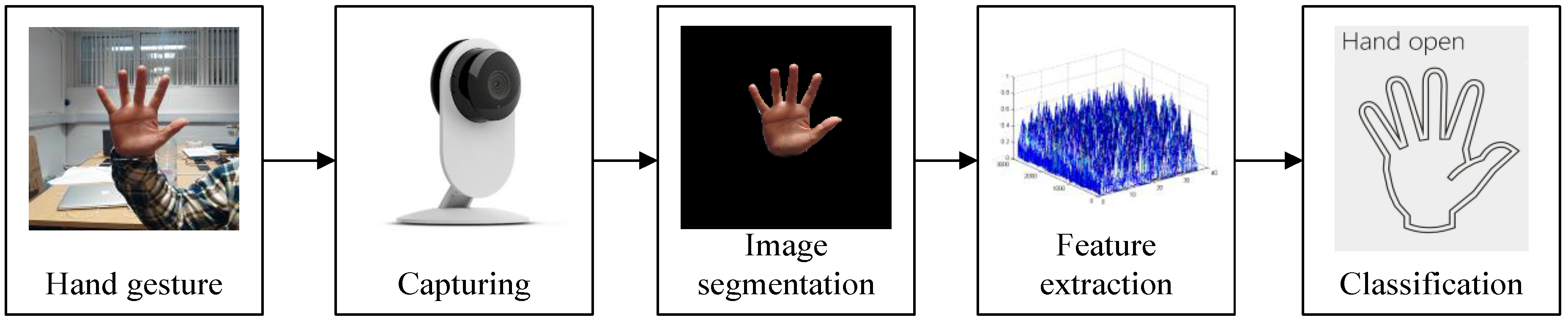
:1. Introduction
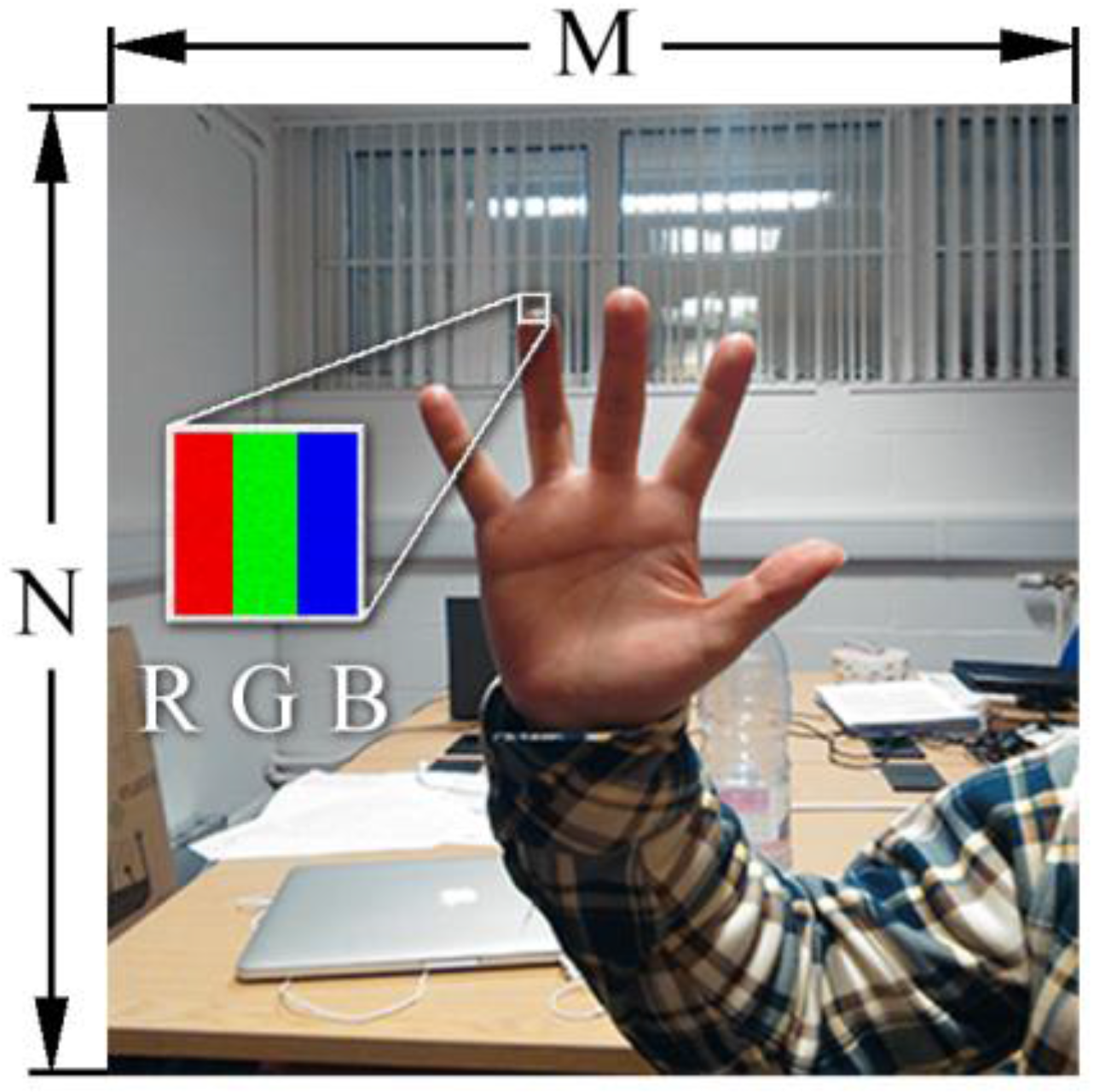
2. Modelling of Hand Gesture Images
2.1. Single Gaussian Model
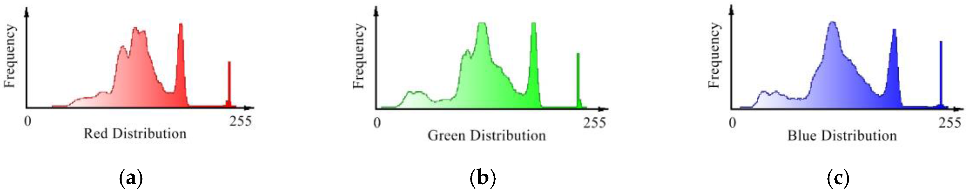
2.2. Gaussian Mixture Model of RGB Image
2.3. Expectation Maximum Algorithm
- Initialization: Initialize with random numbers [27], and the unit matrices are used as covariance matrices to start the first iteration. The mixed coefficients or prior probability is assumed as .
- E-step: Compute the posterior probability of using current parameters:
- M-step: Renew the parameters:
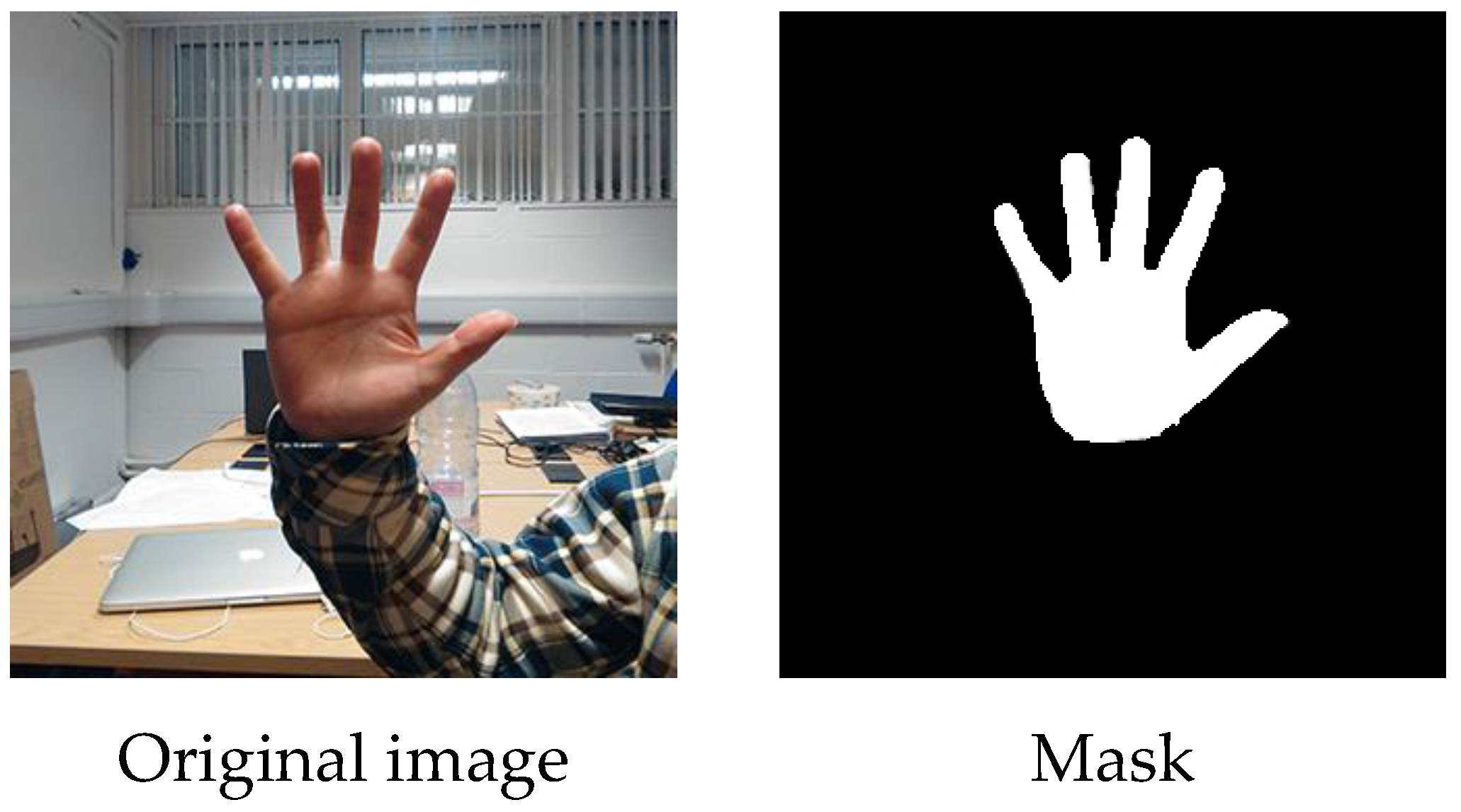
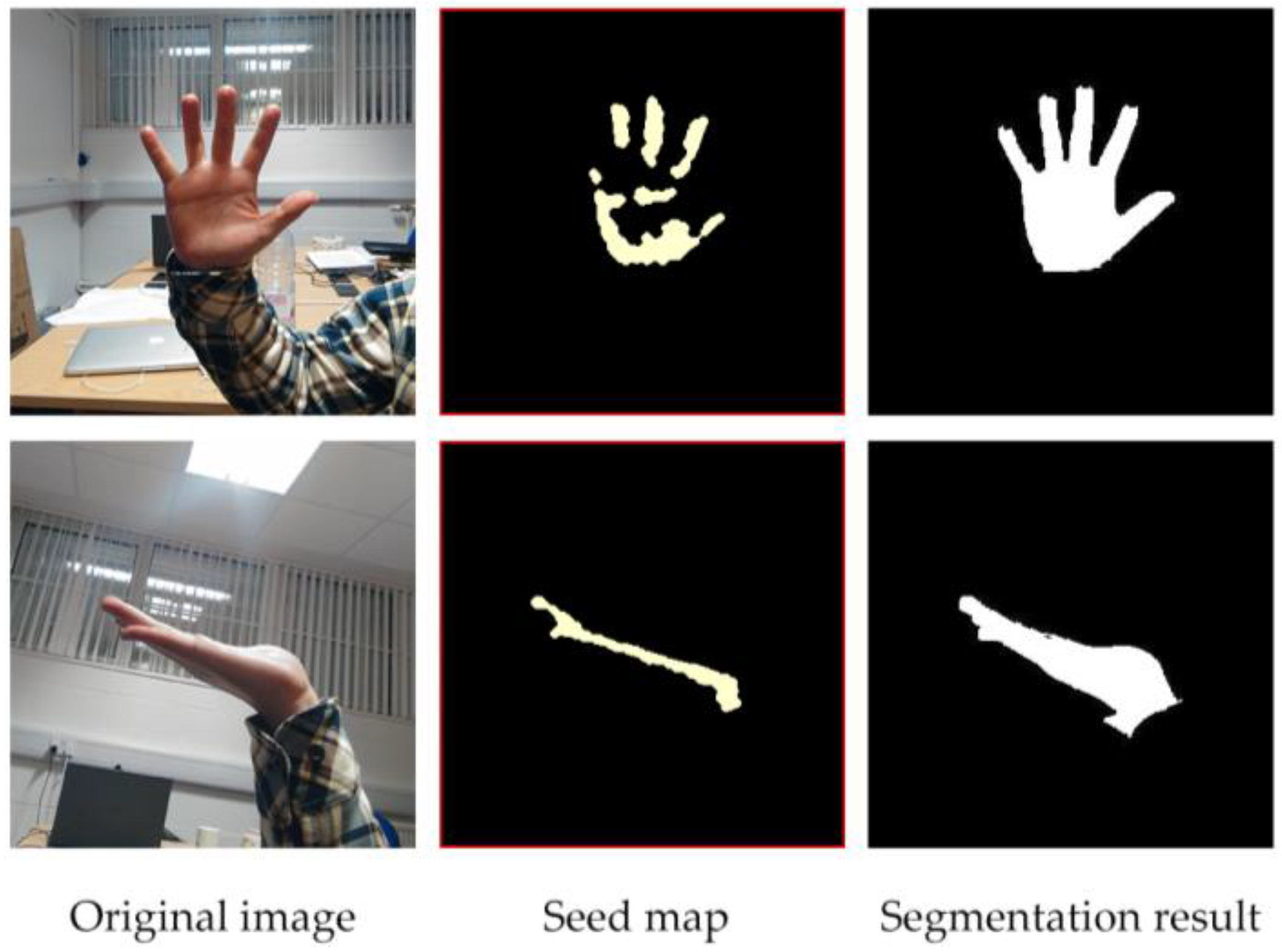
3. Interactive Image Segmentation
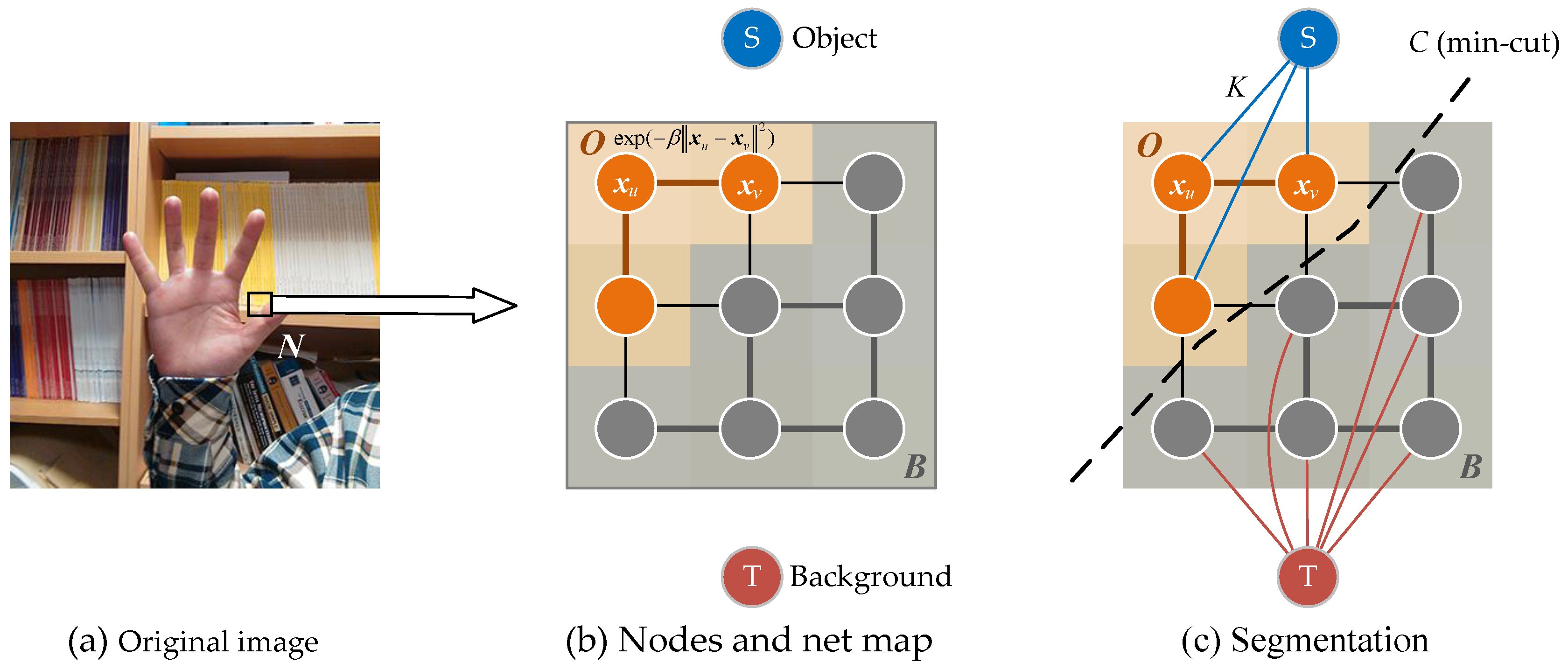
3.1. Gibbs Random Field
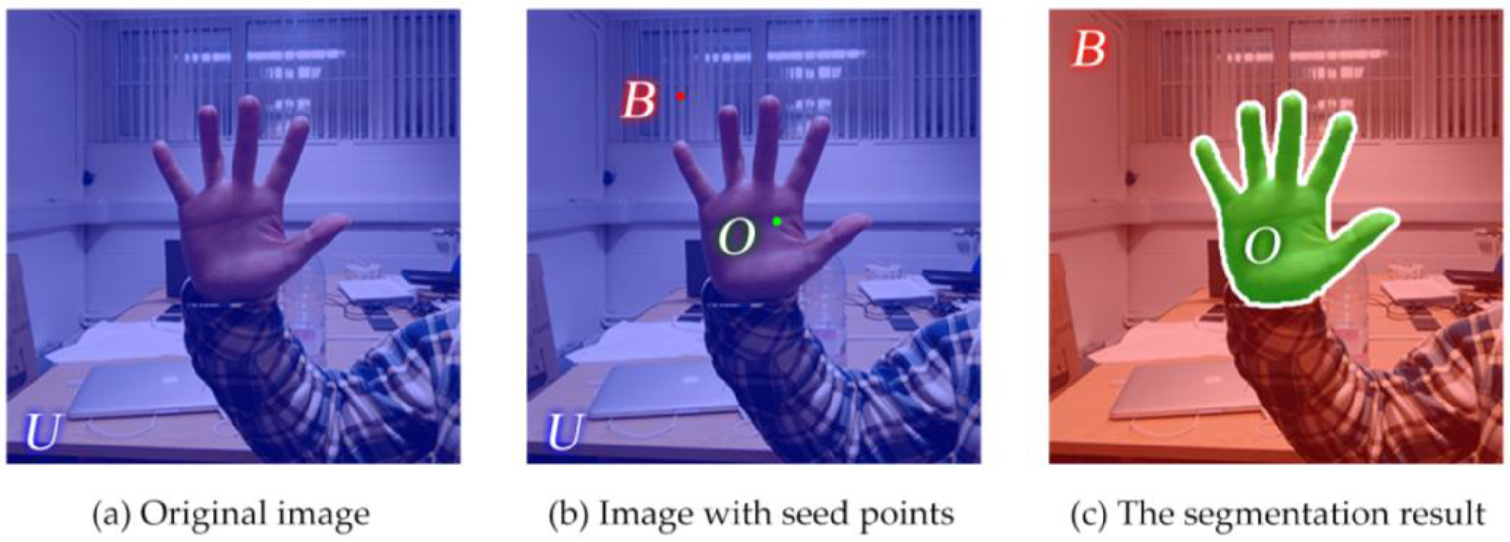
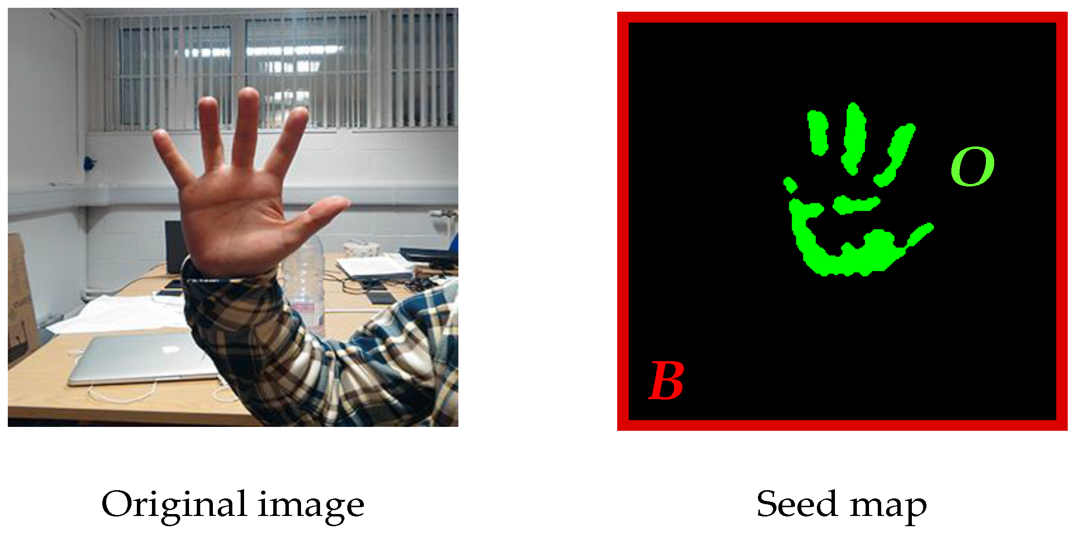
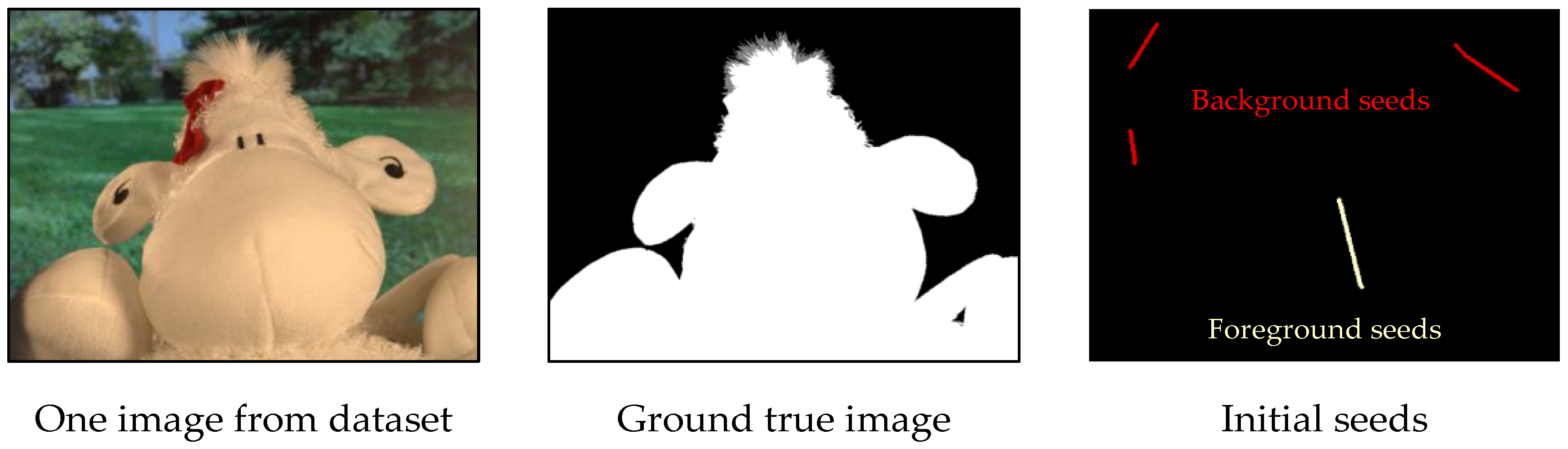
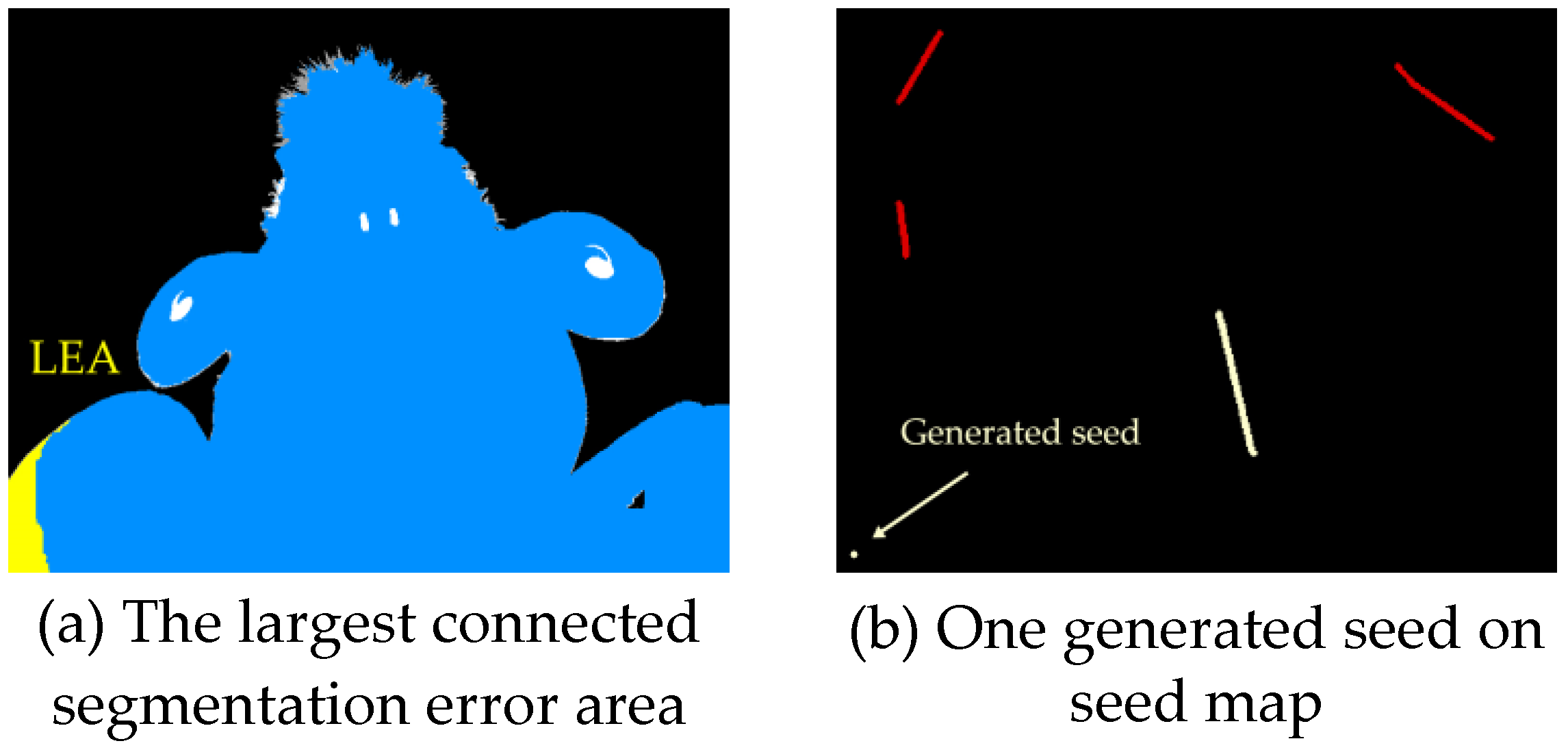
3.2. Automatical Seed Selection
3.3. Min-Cut/Max-Flow Algorithm
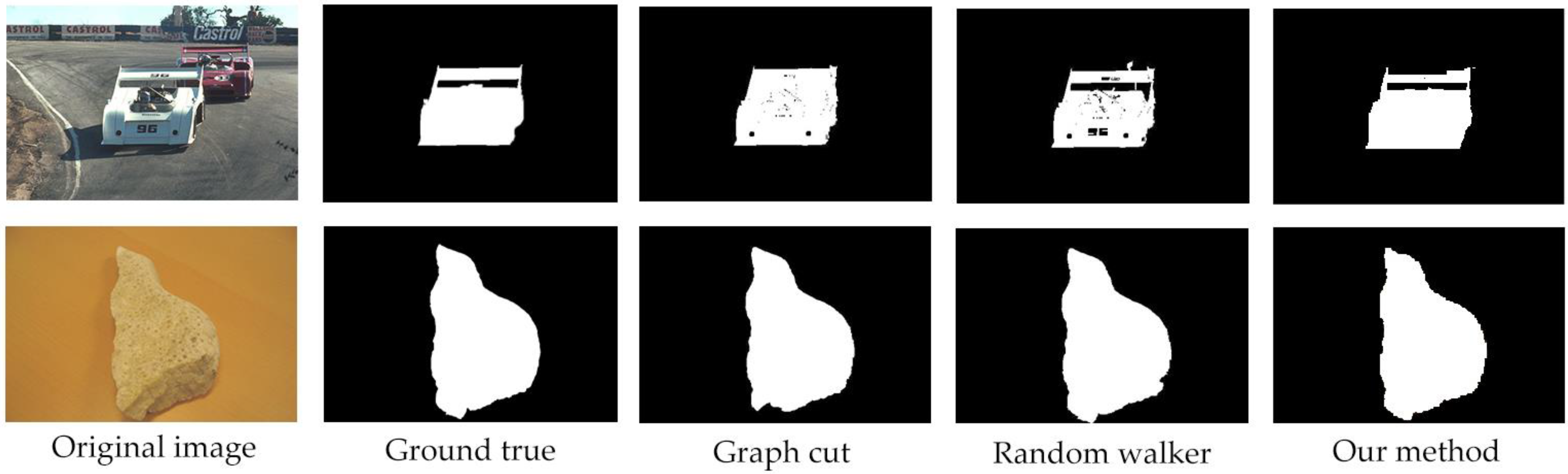
4. Experimental Comparison
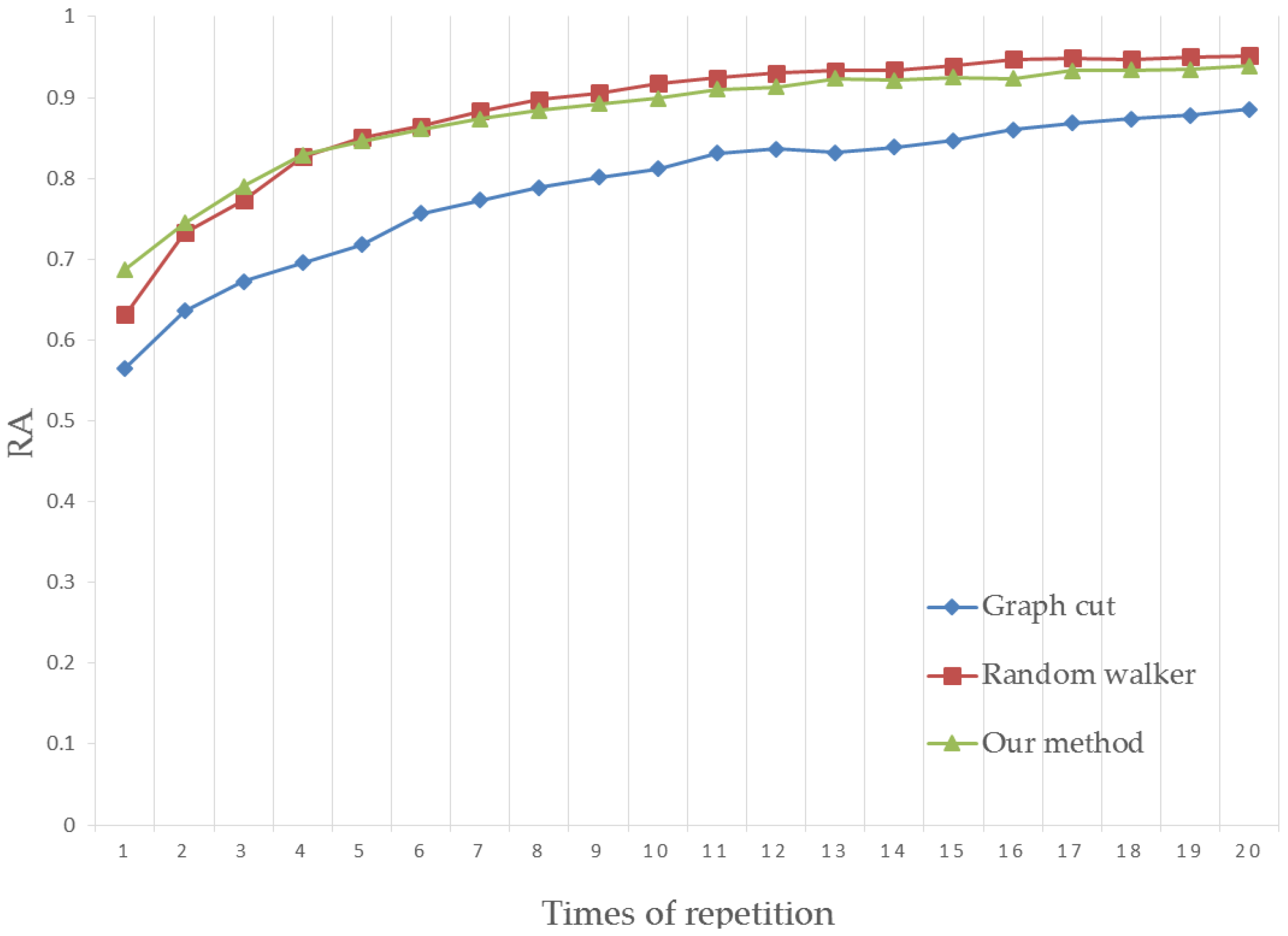
4.1. Region Accuracy
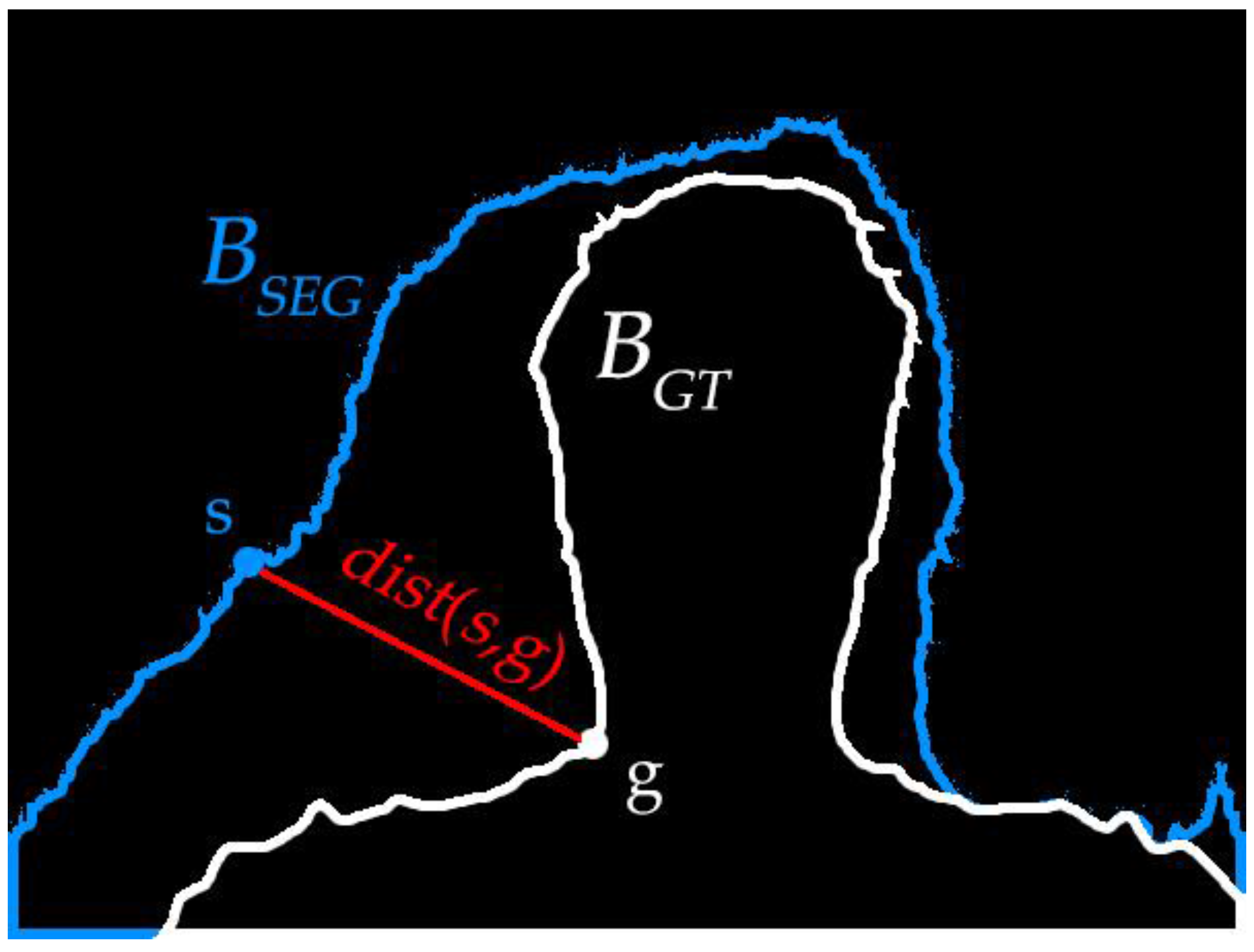
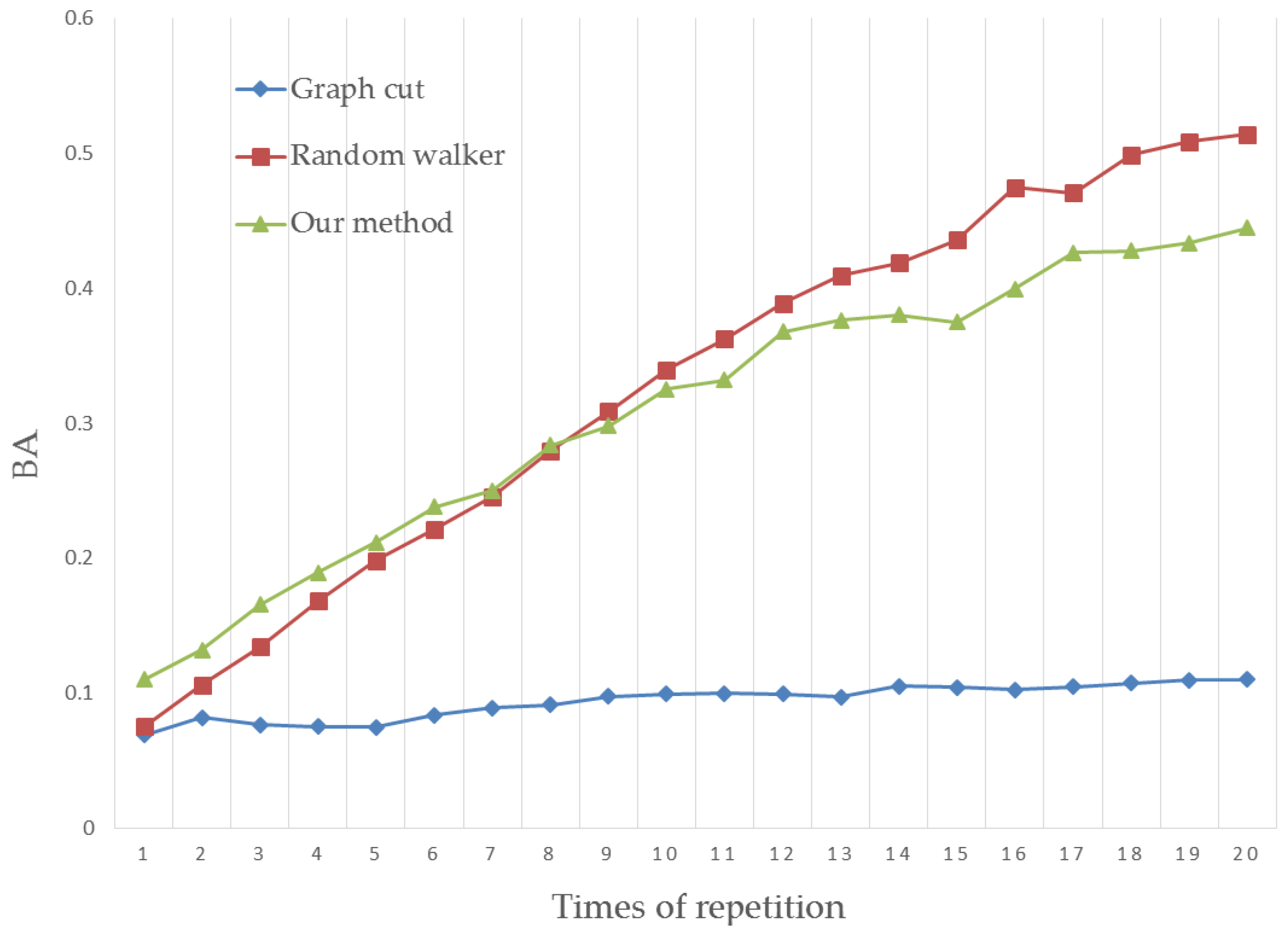
4.2. Boundary Accuracy
4.3. Results Analysis
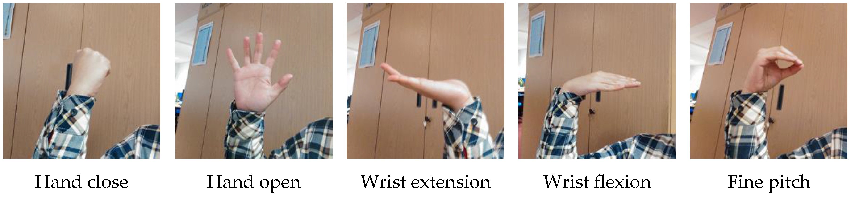
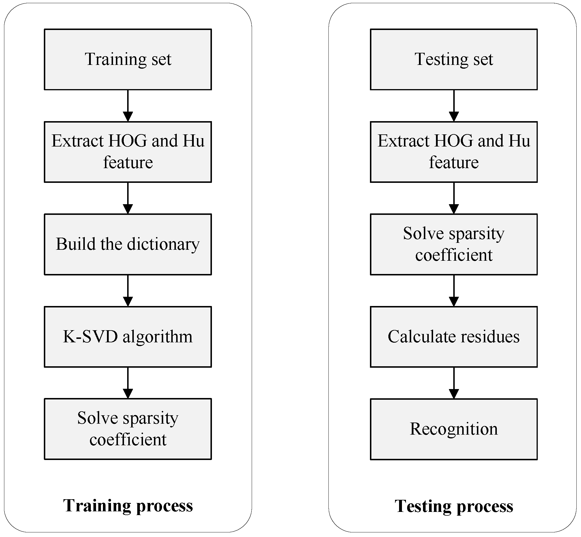
5. Hand Gesture Recognition
6. Conclusions and Future Work
Acknowledgments
Author Contributions
Conflicts of Interest
References
- Nardi, B.A. Context and Consciousness: Activity Theory and Human-Computer Interaction; MIT Press: Cambridge, MA, USA, 1996; p. 400. [Google Scholar]
- Chen, D.C.; Li, G.F.; Jiang, G.Z.; Fang, Y.F.; Ju, Z.J.; Liu, H.H. Intelligent Computational Control of Multi-Fingered Dexterous Robotic Hand. J. Comput. Theor. Nanosci. 2015, 12, 6126–6132. [Google Scholar] [CrossRef]
- Ju, Z.J.; Zhu, X.Y.; Liu, H.H. Empirical Copula-Based Templates to Recognize Surface EMG Signals of Hand Motions. Int. J. Humanoid Robot. 2011, 8, 725–741. [Google Scholar] [CrossRef]
- Miao, W.; Li, G.F.; Jiang, G.Z.; Fang, Y.; Ju, Z.J.; Liu, H.H. Optimal grasp planning of multi-fingered robotic hands: A review. Appl. Comput. Math. 2015, 14, 238–247. [Google Scholar]
- Farina, D.; Jiang, N.; Rehbaum, H.; Holobar, A.; Graimann, B.; Dietl, H.; Aszmann, O.C. The extraction of neural information from the surface EMG for the control of upper-limb prostheses: Emerging avenues and challenges. IEEE Trans. Neural Syst. Rehabil. Eng. 2014, 22, 797–809. [Google Scholar] [CrossRef] [PubMed]
- Ju, Z.; Liu, H. Human Hand Motion Analysis with Multisensory Information. IEEE/ASME Trans. Mechatron. 2014, 19, 456–466. [Google Scholar] [CrossRef]
- Panagiotakis, C.; Papadakis, H.; Grinias, E.; Komodakis, N.; Fragopoulou, P.; Tziritas, G. Interactive Image Segmentation Based on Synthetic Graph Coordinates. Pattern Recognit. 2013, 46, 2940–2952. [Google Scholar] [CrossRef]
- Yang, D.F.; Wang, S.C.; Liu, H.P.; Liu, Z.J.; Sun, F.C. Scene modeling and autonomous navigation for robots based on kinect system. Robot 2012, 34, 581–589. [Google Scholar] [CrossRef]
- Wang, C.; Liu, Z.; Chan, S.C. Superpixel-Based Hand Gesture Recognition with Kinect Depth Camera. Trans. Multimed. 2015, 17, 29–39. [Google Scholar] [CrossRef]
- Sinop, A.K.; Grady, L. A Seeded Image Segmentation Framework Unifying Graph Cuts and Random Walker Which Yields a New Algorithm. In Proceedings of the IEEE 11th International Conference on Computer Vision (ICCV), Rio de Janeiro, Brazil, 14–20 October 2007; pp. 1–8.
- Grady, L. Multilabel random walker image segmentation using prior models. In Proceedings of the IEEE Computer Society Conference on Computer Vision and Pattern Recognition (CVPR’05), San Diego, CA, USA, 20–26 June 2005; pp. 763–770.
- Couprie, C.; Grady, L.; Najman, L.; Talbot, H. Power watersheds: A new image segmentation framework extending graph cuts, random walker and optimal spanning forest. In Proceedings of the IEEE 12th International Conference on Computer Vision (ICCV), Kyoto, Japan, 27 September–4 October 2009; pp. 731–738.
- Varun, G.; Carsten, R.; Antonio, C.; Andrew, B.; Andrew, Z. Geodesic star convexity for interactive image segmentation. In Proceedings of the IEEE CVPR, San Francisco, CA, USA, 13–18 June 2010; pp. 3129–3136.
- Ju, Z.; Liu, H. A Unified Fuzzy Framework for Human Hand Motion Recognition. IEEE Trans. Fuzzy Syst. 2011, 19, 901–913. [Google Scholar]
- Xu, Y.; Yu, G.; Wang, Y.; Wu, X.; Ma, Y. A Hybrid Vehicle Detection Method Based on Viola-Jones and HOG + SVM from UAV Images. Sensors 2016, 16, 1325. [Google Scholar] [CrossRef] [PubMed]
- Fernando, M.; Wijjayanayake, J. Novel Approach to Use Hu Moments with Image Processing Techniques for Real Time Sign Language Communication. Int. J. Image Process. 2015, 9, 335–345. [Google Scholar]
- Chen, Q.; Georganas, N.D.; Petriu, E.M. Real-time vision-based hand gesture recognition using haar-like features. In Proceedings of the EEE Instrumentation & Measurement Technology Conference IMTC, Warsaw, Poland, 1–3 May 2007; pp. 1–6.
- Sun, R.; Wang, J.J. A Vehicle Recognition Method Based on Kernel K-SVD and Sparse Representation. Pattern Recognit. Artif. Intell. 2014, 27, 435–442. [Google Scholar]
- Jiang, Y.V.; Won, B.-Y.; Swallow, K.M. First saccadic eye movement reveals persistent attentional guidance by implicit learning. J. Exp. Psychol. Hum. Percept. Perform. 2014, 40, 1161–1173. [Google Scholar] [CrossRef] [PubMed]
- Ju, Z.; Liu, H.; Zhu, X.; Xiong, Y. Dynamic Grasp Recognition Using Time Clustering, Gaussian Mixture Models and Hidden Markov Models. Adv. Robot. 2009, 23, 1359–1371. [Google Scholar] [CrossRef]
- Bian, X.; Zhang, X.; Liu, R.; Ma, L.; Fu, X. Adaptive classification of hyperspectral images using local consistency. J. Electron. Imaging 2014, 23, 063014. [Google Scholar]
- Song, H.; Wang, Y. A spectral-spatial classification of hyperspectral images based on the algebraic multigrid method and hierarchical segmentation algorithm. Remote Sens. 2016, 8, 296. [Google Scholar] [CrossRef]
- Hatwar, S.; Anil, W. GMM based Image Segmentation and Analysis of Image Restoration Tecniques. Int. J. Comput. Appl. 2015, 109, 45–50. [Google Scholar] [CrossRef]
- Couprie, C.; Najman, L.; Talbot, H. Seeded segmentation methods for medical image analysis. In Medical Image Processing; Springer: New York, NY, USA, 2011; pp. 27–57. [Google Scholar]
- Bańbura, M.; Modugno, M. Maximum likelihood estimation of factor models on datasets with arbitrary pattern of missing data. J. Appl. Econ. 2014, 29, 133–160. [Google Scholar] [CrossRef]
- Simonetto, A.; Leus, G. Distributed Maximum Likelihood Sensor Network Localization. IEEE Trans. Signal Process. 2013, 62, 1424–1437. [Google Scholar] [CrossRef]
- Ju, Z.; Liu, H. Fuzzy Gaussian Mixture Models. Pattern Recognit. 2012, 45, 1146–1158. [Google Scholar] [CrossRef]
- Zhang, Y.; Brady, M.; Smith, S. Segmentation of brain MR images through a hidden Markov random field model and the expectation-maximization algorithm. IEEE Trans. Med. Imaging 2001, 20, 45–57. [Google Scholar] [CrossRef] [PubMed]
- Song, W.; Cho, K.; Um, K.; Won, C.S.; Sim, S. Intuitive terrain reconstruction using height observation-based ground segmentation and 3D object boundary estimation. Sensors 2012, 12, 17186–17207. [Google Scholar] [CrossRef] [PubMed]
- Wei, S.; Kyungeun, C.; Kyhyun, U.; Chee, S.; Sungdae, S. Complete Scene Recovery and Terrain Classification in Textured Terrain Meshes. Sensors 2012, 12, 11221–11237. [Google Scholar]
- Liao, L.; Lin, T.; Li, B.; Zhang, W. MR brain image segmentation based on modified fuzzy C-means clustering using fuzzy GIbbs random field. J. Biomed. Eng. 2008, 25, 1264–1270. [Google Scholar]
- Kakumanu, P.; Makrogiannis, S.; Bourbakis, N. A survey of skin-color modeling and detection methods. Pattern Recognit. 2007, 40, 1106–1122. [Google Scholar] [CrossRef]
- Lee, G.; Lee, S.; Kim, G.; Park, J.; Park, Y. A Modified GrabCut Using a Clustering Technique to Reduce Image Noise. Symmetry 2016, 8, 64. [Google Scholar] [CrossRef]
- Ning, J.; Zhang, L.; Zhang, D.; Wu, C. Interactive image segmentation by maximal similarity based region merging. Pattern Recognit. 2010, 43, 445–456. [Google Scholar] [CrossRef]
- Grabcut Image Dataset. Available online: http://research.microsoft.com/enus/um/cambridge/projects/visionimagevideoediting/segmentation/grabcut.htm (accessed on 18 December 2016).
- Everingham, M.; Van, G.L.; Williams, C.K.; Winn, I.J.; Zisserman, A. The PASCAL Visual Object Classes Challenge 2009 (VOC2009) Results. Available online: http://host.robots.ox.ac.uk/pascal/VOC/voc2009/ (accessed on 26 December 2016).
- Rhemann, C.; Rother, C.; Wang, J.; Gelautz, M.; Kohli, P.; Rott, P. A perceptually motivated online benchmark for image matting. In Proceedings of the CVPR, Miami, FL, USA, 20–25 June 2009; pp. 1826–1833.
- Margolin, R.; Zelnik-Manor, L.; Tal, A. How to Evaluate Foreground Maps? In Proceedings of the IEEE Conference on Computer Vision and Pattern Recognition, Columbus, OH, USA, 23–28 June 2014; pp. 248–255.
- Zhao, Y.; Nie, X.; Duan, Y. A benchmark for interactive image segmentation algorithms. In Proceedings of the IEEE Person-Oriented Vision, Kona, HI, USA, 7 January 2011; pp. 33–38.
- Zhou, Y.; Liu, K.; Carrillo, R.E.; Barner, K.E.; Kiamilev, F. Kernel-based sparse representation for gesture recognition. Pattern Recognit. 2013, 46, 3208–3222. [Google Scholar] [CrossRef]
- Yu, F.; Zhou, F. Classification of machinery vibration signals based on group sparse representation. J. Vibroeng. 2016, 18, 1540–1545. [Google Scholar] [CrossRef]


| Link Type | Weight | Precondition |
|---|---|---|
| K | ||
| 0 | ||
| 0 | ||
| K | ||
| where | ||
| Gestures | Recognition Rates |
|---|---|
| Hand close | 86.7% |
| Hand open | 73.3% |
| Wrist extension | 100% |
| Wrist flexion | 100% |
| Fine pitch | 66.7% |
| Over all rate | 85.3% |
| Gestures | Recognition Rates |
|---|---|
| Hand close | 93.3% |
| Hand open | 100% |
| Wrist extension | 100% |
| Wrist flexion | 100% |
| Fine pitch | 100% |
| Over all rate | 98.7% |
© 2017 by the authors. Licensee MDPI, Basel, Switzerland. This article is an open access article distributed under the terms and conditions of the Creative Commons Attribution (CC BY) license ( http://creativecommons.org/licenses/by/4.0/).
Share and Cite
Chen, D.; Li, G.; Sun, Y.; Kong, J.; Jiang, G.; Tang, H.; Ju, Z.; Yu, H.; Liu, H. An Interactive Image Segmentation Method in Hand Gesture Recognition. Sensors 2017, 17, 253. https://doi.org/10.3390/s17020253
Chen D, Li G, Sun Y, Kong J, Jiang G, Tang H, Ju Z, Yu H, Liu H. An Interactive Image Segmentation Method in Hand Gesture Recognition. Sensors. 2017; 17(2):253. https://doi.org/10.3390/s17020253
Chicago/Turabian StyleChen, Disi, Gongfa Li, Ying Sun, Jianyi Kong, Guozhang Jiang, Heng Tang, Zhaojie Ju, Hui Yu, and Honghai Liu. 2017. "An Interactive Image Segmentation Method in Hand Gesture Recognition" Sensors 17, no. 2: 253. https://doi.org/10.3390/s17020253
APA StyleChen, D., Li, G., Sun, Y., Kong, J., Jiang, G., Tang, H., Ju, Z., Yu, H., & Liu, H. (2017). An Interactive Image Segmentation Method in Hand Gesture Recognition. Sensors, 17(2), 253. https://doi.org/10.3390/s17020253