1. Introduction
It is well known that the widespread application of the Global Navigation Satellite System (GNSS) has promoted the construction, improvement, and modernization of satellite navigation systems such as GPS and Galileo in major countries and regions of the world [
1,
2]. Among them, China’s BeiDou system has seen rapid development in recent years. The BeiDou regional system began its service to the Asia Pacific region in 2012, while the BeiDou global system has entered the deployment phase in 2017 and will complete global networking in 2020 [
3,
4]. On the premise of guaranteed forward compatibility of open service to legacy users, the BeiDou global system will broadcast several new navigation signals in the B1, B2, and B3 frequency bands to achieve better performance in terms of accuracy, sensitivity, and robustness [
5]. Of particular note is that two civilian navigation signals—B1I and B1C—modulated at different center frequencies in the B1 frequency band will be provided in the BeiDou global system. While the B1I signal [
6], with a center frequency of 1561.098 MHz, is retained from the regional system to offer service to legacy users, the new B1C signal, with a center frequency of 1575.42 MHz and which is implemented by the state-of-the-art multiplexed binary offset carrier (MBOC) modulation scheme, will be broadcasted mainly to offer interoperability with GPS L1C and Galileo E1C signals [
7].
Traditionally, each satellite in the GNSS constellation broadcasts multiple navigation signals in the same or different frequency bands. For example, GPS broadcasts both a L1C/A signal and a L1P (Y) signal in the L1 band while broadcasting a L2P (Y) signal in the L2 band; in the modernization of GPS, the newly added L5 signal contains both data and pilot channels, which can also be viewed as a special case of broadcasting two signals at the same frequency [
8]. Because two or more navigation signals broadcast by one satellite are generated based on the same onboard reference clock and their propagation paths to the receiver antenna are nearly the same, the time delay and Doppler-shift of these signals at the receiver are strongly correlated. This is the basis for the joint processing of multiple signals to achieve better measurement performance.
Various techniques have been developed for the joint processing of multiple navigation signals, and they can be grouped into three types. The first type of joint processing is based on a tracking loop. The time delay and Doppler-shift parameters obtained by tracking a strong signal are used to assist in tracking the weak signal. One typical example is the GPS receiver with dual-frequency positioning, which utilizes the L1 signal to assist semi-codeless tracking of the L2P(Y) signal [
8,
9,
10]. This type of joint processing handles two signals separately in essence, and can improve tracking sensitivity for the weak signal at the parameter level. The second type of joint processing is based on code and/or phase discriminators. For instance, when receiving the L5 signal, the outputs from code and phase discriminators of the data and pilot channels can be coherently or non-coherently combined to improve the accuracy and sensitivity of tracking [
11,
12]. The third type is based on the auto-correlation function (ACF). By quasi-coherently combining correlator outputs of L1C and L1C/A signal components, the proposed algorithm in [
13] successfully constructs a synthesis correlation function with no side-peaks. In addition, it combines the power of two signals to improve the tracking accuracy. These three types of joint processing implement different ways of jointly utilizing the power of multiple signals. We hence refer to this kind of performance improvement as power gain.
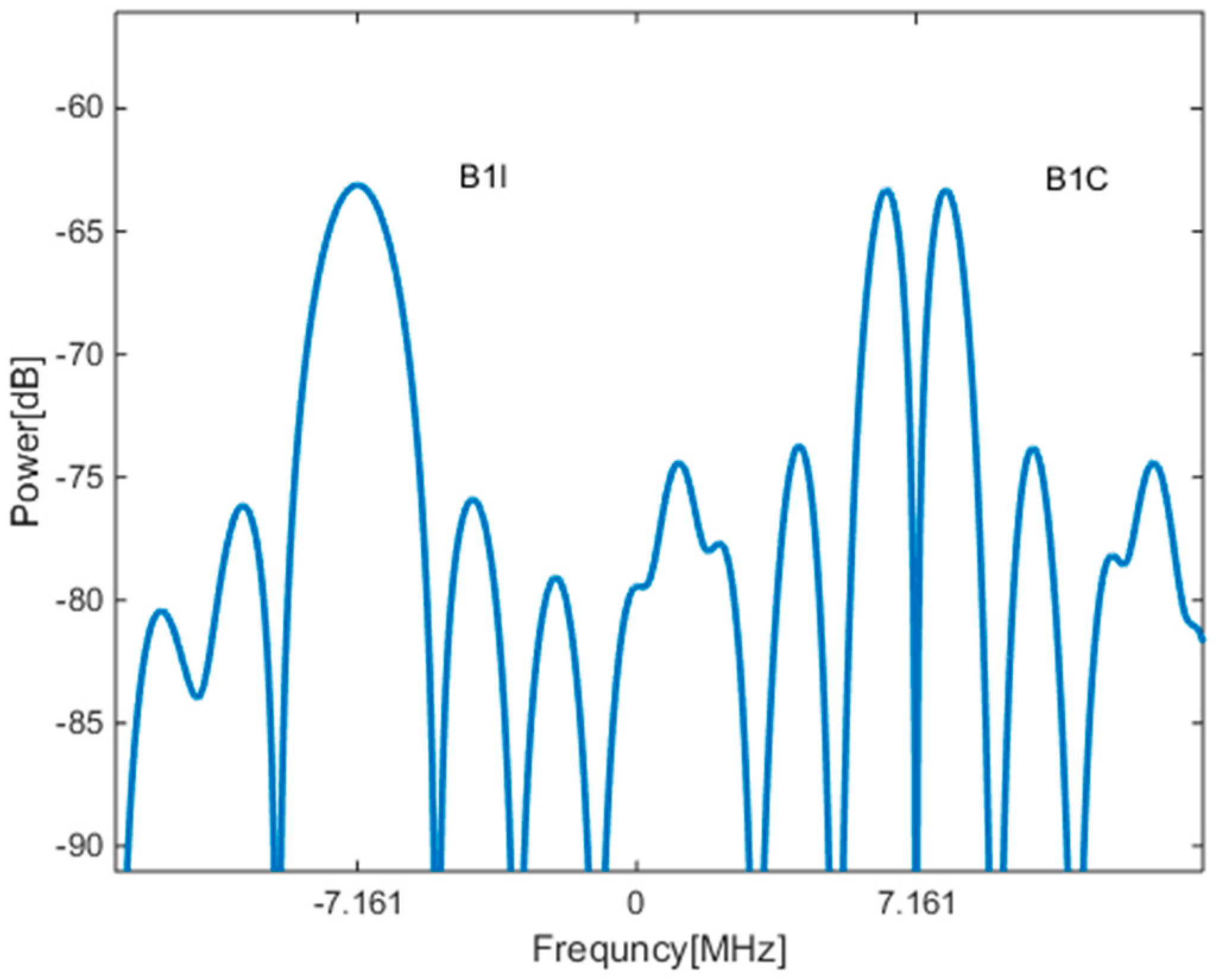
The unique features of the B1I and B1C signals in the BeiDou global system, however, offer more potential than can be exploited by the three schemes described above. First, compared to GPS L5 data/pilot channels or L1C/A and L1C signals, B1I and B1C signals are modulated at different center frequencies in the B1 frequency band [
6,
14], which brings about a bandwidth gain in addition to power gain. In addition, the center frequencies of B1I and B1C signals are separated by only 14.322 MHz, which is much closer than the ≥300 MHz separation between the center frequencies of the GPS L1C/A and L2P(Y) signals. As a result, both signals can be received by one broadband radio channel simultaneously, and the ionosphere delays experienced by these two signals are almost identical. To take full advantage of such unique characteristics of B1I and B1C, a better joint processing approach is clearly desired.
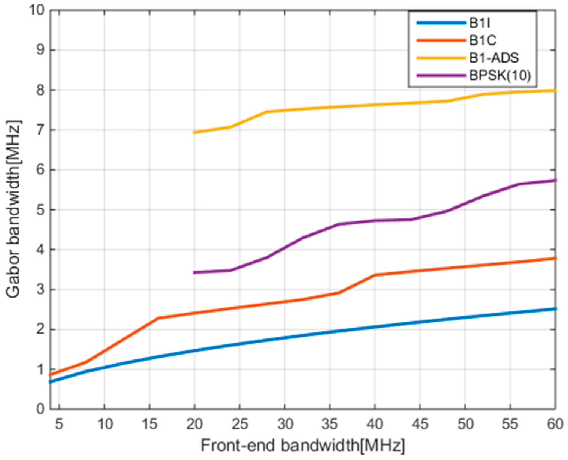
In this paper we first propose to view B1I and B1C signals as one virtual navigation signal with Asymmetric Dual Sidebands, named B1-ADS. The theoretical analysis in the following shows that the Gabor bandwidth of this virtual asymmetric signal is much wider than those of B1I and B1C, and even wider than those of signals modulated by Binary Phase Shift Keying (BPSK) (10) such as L1P(Y) and L5. This indicates that the ranging accuracy of this virtual signal is much higher than that of B1I or B1C alone. What needs to be emphasized here is that the performance improvement is mainly due to bandwidth gain rather than power gain. Although the impressive potential for improved ranging accuracy is indicated by the result of theoretical analysis, it still remains a big challenge in current receiver design to implement optimal reception processing for B1-ADS signals. On one hand, the traditional joint processing methods mentioned above, such as tracking loop parameter aiding or combining discriminator outputs of different signals, fail to take advantage of the bandwidth gain for the B1-ADS signal. On the other hand, although this B1-ADS signal has the frequency separation characteristic similar to the BOC-modulated signal, the complexity of its ACF caused by the asymmetry between the upper and lower sidebands renders those classical reception techniques of the BOC signal, such as Bump-Jump [
15] and the Double Estimator Technique (DET) [
16], impossible to apply directly.
So, in this paper, we further present a novel ASYMmetric Dual-Band Tracking technique to achieve the optimal reception processing of B1-ADS signals through harvesting both power gain and bandwidth gain, which is abbreviated as ASYM-DBT. The key of ASYM-DBT is to construct discriminators of code delay, subcarrier, and carrier by coherently combining the correlator outputs of dual sideband signals and to track these three components by delay lock loop (DLL), subcarrier lock loop (SLL) and phase lock loop (PLL), respectively. The much-improved ranging accuracy committed by the B1-ADS signal is obtained by combining the outputs of the code delay and the subcarrier tracking loops. In fact, ASYM-DBT is an extension of our team’s previously proposed Dual BPSK Tracking method (DBT) [
17] designed for optimal reception of an alternative BOC (AltBOC) signal. The DBT method adopts the ideas of DET and double phase estimator (DPE) [
18] to treat the subcarrier of BOC signals independently and to track it by an additional loop, but the characteristic of no need to generate a subcarrier makes this method have lower hardware complexity and more generality. A similar method to DBT is also mentioned in [
19]. As an extension of the original DBT method, ASYM-DBT has been improved to cope with the more complicated asymmetric case of dual-sideband signals with different modulation schemes, power, and initial phase relations.
The remainder of this paper is organized as follows: in
Section 2, the BDS B1I and B1C signal properties are described and the power spectral density (PSD), ACF, and Gabor bandwidth of the whole B1-ADS signal are given and analyzed. In
Section 3, we propose a reception model for the B1-ADS signal. In
Section 4, the ASYM-DBT method is described in detail, including tracking channel architecture and its theoretical thermal noise performance. In
Section 5, a software-defined receiver developed by Tsinghua University is used to process B1I and B1C signals from a signal generator. A simulated experiment is designed to verify the theoretical thermal noise performance of the ASYM-DBT method. Finally, conclusions are drawn in
Section 6.
3. Reception Model of B1-ADS Signal
While the theoretical analysis of the frequency domain and ACF in the previous section shows that the B1-ADS signal has an excellent potential for ranging accuracy, we will further discuss the time domain reception model of the B1-ADS signal in this section for designing the optimal reception algorithm. As mentioned earlier, the B1C signal adopts the data-plus-pilot signal structure, and the pilot signal also includes the components of BOC(1,1) and BOC(6,1). To facilitate subsequent analysis and expression, without losing generality, a pilot tracking and data demodulation strategy that neglects the BOC(6,1) component will be adopted for the B1C signal. In other words, the B1-ADS signal discussed below will be simplified to consisting of the B1I signal on the lower band and the BOC(1,1) component of the B1C pilot signal on the upper band.
In this paper, the B1-ADS signal is assumed to be received in the presence of thermal noise at the receiver front end that can be modeled as stationary additive white Gaussian noise. As a result, the received signal can be expressed as follows:
where
is the signal propagation delay, and
is the thermal noise. In Equation (6), the delayed B1-ADS signal is represented as a composite of B1I and B1C signals:
where
,
and
represent received frequency, initial carrier phase, and amplitude of the corresponding components, respectively. The values
and
are the baseband waveforms of the B1I and B1C signals, which are the combination of subcarrier, ranging code, secondary code, and navigation data bit. The received frequency may be further expressed as a sum of the transmitted nominal frequency
and Doppler frequency
as follows,
Next, we want to rewrite Equation (6) with the parameters of the B1-ADS signal. The nominal carrier frequency and subcarrier frequency of the B1-ADS signal are introduced and defined in Equation (8), and the initial phases of carrier and subcarrier are given in Equation (9):
where the subscripts
and
are used to indicate carrier and subcarrier, respectively. Since the Doppler frequency scales linearly with the signal center frequency, the Doppler frequencies of both the carrier and subcarrier of B1-ADS signal can be represented in terms of the Doppler frequencies of the B1I and B1C signals as follows:
Then, the received frequencies of the carrier and subcarrier of the B1-ADS signal are given in Equation (11),
By Equations (7)–(11), Equation (6) is rewritten based on the parameters of the B1-ADS signal as:
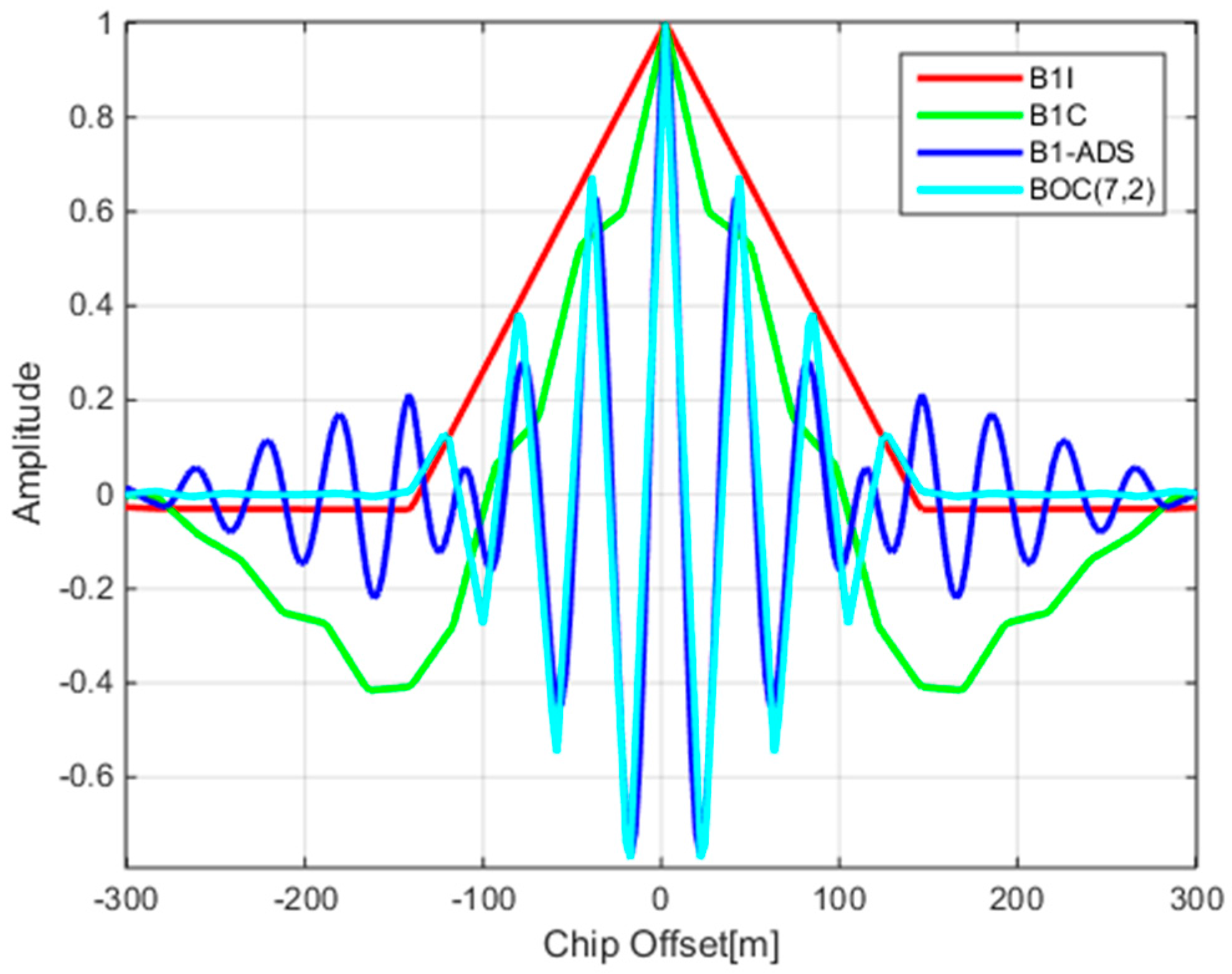
Equation (12) is the basis for the subsequent design of a reception and processing algorithm. This representation of the B1-ADS signal can further reveal the similarity between itself and the regular BOC signal. Assuming that the baseband waveforms and the amplitudes of both the B1I and B1C signals are the same in Equation (12), the B1-ADS signal can be considered as a special BOC signal with a carrier frequency of 1568.259 MHz and a subcarrier frequency of 7.161 MHz. This explains the similarity of the ACFs of the B1-ADS and BOC(7,2) signals in
Figure 3.
4. The ASYM-DBT Method and Thermal Noise Performance Analysis
Although the B1-ADS signal has characteristics similar to that of the BOC signal, it is very difficult to obtain and generate the true subcarrier waveform due to the two components of B1-ADS with unequal power and different modulation schemes. This renders those reception techniques of BOC signals that need to generate local subcarrier waveforms, such as Bump-Jump [
15] and DET [
16], impossible to apply to the B1-ADS signal. To tackle this problem, we start with the reception model given in Equation (12), extend the previous Dual BPSK Tracking method [
17] designed for optimal reception of the AltBOC signal, and propose a novel Asymmetric Dual-Band Tracking technique to achieve the optimal reception processing of B1-ADS signal, which we abbreviate as ASYM-DBT.
4.1. The ASYM-DBT Method
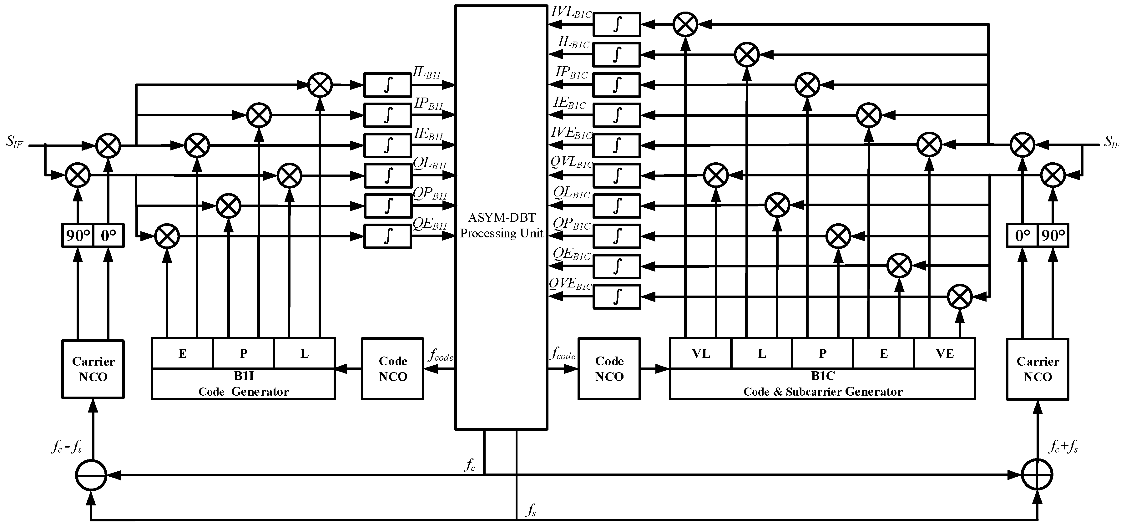
Figure 4 depicts the tracking channel architecture of ASYM-DBT for the B1-ADS signal, which consists of two groups of different types of correlators and one processing unit. Two groups of correlators on the left and right are used to correlate the received signal with locally generated B1I and B1C signals, respectively. Their outputs are then fed into the processing unit in the middle. The processing unit is responsible for combining the outputs of the two groups of correlators coherently or non-coherently, forming the discriminator outputs of the code, subcarrier, and carrier, and filtering them. Closed loops for code, subcarrier, and carrier tracking are finally formed by feeding their corrected NCO frequencies back to the correlators. Three kinds of measurements—code phase
, subcarrier phase
, and carrier phase
—can be extracted from the corresponding loops. As can be seen in the next section, code tracking errors are on the order of decimeters, subcarrier tracking error is on the order of centimeters. Therefore, a natural idea is to combine the subcarrier phase measurement (which is high-precision but ambiguous) with the code measurement (which is just the opposite) to form a high-precision and unambiguous measurement given the subcarrier wavelength of 42.9 m, as shown below [
17]:
where
represents the combined pseudorange measurement and
represents the subcarrier wavelength.
The following describes the outputs of correlators and ASYM-DBT algorithms in the processing unit in detail.
4.1.1. Correlator
In
Figure 4 the local B1I signals generated on the left side and the local B1C signals generated on the right side are used to correlate with the incoming IF signal, respectively. The B1I correlator is the conventional BPSK-type correlator. The locally generated signals are defined as the six possible combinations of in-phase (I) and quadra-phase (Q) local carrier replicas and early (E), prompt (P), and late (L) local code replicas [
1]. The B1C correlator is the classical BOC(1,1)-type correlator. The locally generated signals are defined as the ten possible combinations of in-phase and quadra-phase local carrier replicas and very early (VE), early, prompt, late, and very late (VL) local code replicas. This setting supports the Bump-Jump algorithm in detecting and recovering from a false lock in the single-band processing mode based on the comparison of the main and side peak amplitudes.
According to Equation (12), it is not difficult to discover that B1I and B1C signals are mutually orthogonal frequency-wise and code-wise. This means one signal has little influence on the correlator outputs of the other signal on the other sideband. For simplicity, and to clarify the concepts underlying the algorithm design, the thermal noise term in (2) is dropped. Thus, the outputs of the two groups of correlators can be approximately expressed as follows:
where
and
are the normalized ACFs of the B1I and B1C signals, respectively;
and
are the correlator spacing; T represents the pre-detection integration time;
,
,
are the residual errors for code, subcarrier, and carrier phases; and “^” denotes the previous estimates of the variable. Besides this,
and
are introduced here to simplify the expressions.
D represents the navigation message bit of the B1I signal because it does not have a pilot channel. Note that the amplitudes and ACFs of B1I and B1C are not the same due to the unequal power and different modulation schemes, and correlator spacing
, as an adjustable parameter, may be set to different values for two groups of correlators.
4.1.2. Processing Unit
The processing unit supports two working modes of single-band and dual-band processing, and can smoothly switch between the two modes without any hardware modifications. While the single-band processing mode allows separate discriminating and filtering for the B1I and B1C signals at the same time, the dual-band processing mode is used to track the whole wideband signal, B1-ADS.
Figure 5 depicts the processing flow of the two working modes. During the channel initialization phase, the single-band processing mode is first adopted to achieve reliable tracking of both the B1I and B1C signals, respectively and simultaneously. Once separate tracking obtains stable code and carrier parameters of both signals, the processing unit may shift smoothly to the dual-band processing mode to track the B1-ADS signal to obtain the optimal ranging performance. When one sideband undergoes narrow-band interference, the processing unit can shift back to the single-band mode to ensure that at least the signal on the other sideband can be reliably tracked.
Obviously, the dual-band working mode of the processing unit is more complicated and needs to deal with the asymmetry resulting from different modulation schemes and the unequal power of the upper and lower sidebands of B1-ADS. The following will detail those algorithms under this working mode.
• Discriminators for subcarrier and carrier phases
The phase discrimination results of both carrier and subcarrier are calculated based on the prompt branches of two groups of correlators. In the DBT method designed for the AltBOC signal, by virtue of the symmetry between the upper and lower bands and the existence of pilot channels, the coherent combinations of the correlator outputs are directly implemented with the aim of decoupling the subcarrier and carrier phases and hence obtaining their respective estimates. However, this method cannot be applied directly to the B1-ADS signal because the B1I and B1C signals have different power and the B1I signal is only a data channel modulated by the navigation message. Consequently, the carrier and subcarrier phase discriminations of the B1-ADS signal can only be acquired after stripping the B1I navigation message and compensating for the unequal power of the two signals.
To strip the navigation message of B1I, it is necessary to provide an estimation of the message data bit,
. This can be achieved in two ways [
26]. When the signal-to-noise ratio meets the requirement of reliable demodulation, the estimation of the data bits of the message can be directly obtained from the sign of
. Otherwise, the bits may be provided through the assistance data in an Assisted-BDS system.
To compensate for the unequal power of both signals, it is necessary to know the amplitude ratio between two signals, . Under the assumption that the local codes are approximately aligned with the received signal, for the prompt branches of two groups of correlators we have ; then and . Because the propagation paths to the receiver antenna are the same, the amplitude ratio of the received signal is approximately equal to that of the transmitted signal from the satellite, i.e., .
Given the estimated B1I data bit
and the theoretical amplitude ratio of B1I and B1C
, and further assuming that both the B1I and B1C are stably tracked—viz.,
and
in Equation (14) approach zero—then the following coherent combinations can be formulated by applying the trigonometric function equation:
As can be observed from Equation (15), subcarrier and carrier phases are completely separated. Then, phase discriminations of subcarrier and carrier can be achieved by employing the pure PLL discriminator by the optimal four-quadrant arctangent discriminator algorithm as follows:
Note that the pure PLL discriminator is superior to the Costas PLL discriminator with a 6 dB gain in signal tracking threshold [
1].
• Discriminators for code phase
The coherent and non-coherent discrimination results of the code phase are calculated based on the early and late branches of two groups of correlators. In the design of the code phase discriminator for the B1-ADS signal, the difference in ACFs between the B1I and B1C signals and the difference of the correlator spacing between the two groups of correlators must be considered.
The coherent code phase discriminator of the B1-ADS signal is the weighted sum of the coherent discriminators of the B1I and B1C signals as follows [
1,
11]:
where
and
represent the slopes of the main peaks of B1I ACF and B1C ACF, i.e., one and three chip
−1, respectively.
Similarly, the non-coherent code discriminator of the B1-ADS signal is given in the form of the weighted sum of the non-coherent discriminators of the B1I and B1C signals, as written below:
• Loop filters
Since the outputs of the discriminators mentioned above are noisy, the discriminators of code, subcarrier, and carrier are followed by the corresponding loop filters to reduce the noise. In our design, two separate second-order filters are selected for DLL and SLL, while a third-order filter is selected for PLL. Note that carrier-aiding of the code phase and subcarrier phase might be employed in order to achieve more accurate measurements. The three filtered discriminator outputs are then used to drive code and carrier NCOs of the B1I and B1C signals, respectively. Since there is no essential difference between the DBT loop filters and ASYM-DBT loop filters, for simplicity this paper will not discuss different filter configurations; refer to [
1,
17] for details.
4.2. Theoretical Noise Analysis
After detailing the ASYM-DBT method, we analyze its theoretical ranging performance for the B1-ADS signals. For simplicity, thermal noise is generally treated as the dominant source of error for signal tracking. Generally, the thermal noise manifests in the code performance, the subcarrier performance, and the carrier performance.
According to Equation (12), we can safely ignore the interaction between adjacent frequency signals when analyzing the thermal noise performance. By first calculating the signal part and noise part of each single sideband, the combination correlations of the B1-ADS signal and theoretical errors induced by the thermal noise can then be obtained. For simplicity, this paper will not cover the derivation process. With the coherent DLL discriminator, the dual-band thermal noise can be obtained as follows [
27,
28]:
where
represents the equivalent noise bandwidth of the code tracking loop;
and
are the power proportion of the B1C and B1I signals;
represents the PSD of the single-sideband signal, which is normalized to unity over infinite bandwidth;
represents the equivalent dual-band front-end bandwidth;
represents the carrier-to-noise ratio of the total dual band;
represents the E-L correlator spacing. In case of a non-coherent discriminator, the joint dual-band thermal noise is shown below:
The term in the second line represents the squaring loss.
Considering the asymmetric property of the B1-ADS, the associated subcarrier phase error is given by (21a) [
27,
28]:
Similarly, the carrier phase error is given by (21b):
where
and
represent the equivalent noise bandwidth of the subcarrier and carrier tracking loops, respectively. These theoretical results of the thermal noise performance are compared with the experiment results in the next section.
5. Experiment and Discussion
In this section, a simulated experiment is carried out based on a software receiver and a GNSS signal simulator which supports the generation of the BDS global signals. In addition to demonstrating the ranging performance advantage of the B1-ADS signal over separate B1I or B1C signals, the experiment is also used to validate the feasibility of the ASYM-DBT method.
The software receiver is equipped with a wideband RF unit with a center frequency of 1570 MHz and a bandwidth of 52 MHz that can receive both B1I and B1C signals simultaneously. The entire B1 frequency band is converted to the intermediate frequency of 210 MHz in the RF unit, then is digitized with the sampling rate of 120 MHz, and fed into the PC for subsequent signal reception and processing. The main configuration of the PC platform is as follows: Intel(R) Core(TM) i7-6700K CPU, clocked 4.00 GHz, memory 16.0 GB, NVIDIA GeForce GTX TITAN X GPU. The software receiver can be configured as the following three receiving modes: processing the B1I signal independently, processing the B1C signal independently, and processing the B1-ADS signal with the ASYM-DBT algorithm. The pre-detection integration time is set to 10 milliseconds, and the E-L correlation spacing of the B1I and B1C signals are set to one and one-half of the chip length, respectively. The noise bandwidth parameters of code, subcarrier, and carrier tracking loops are set to 0.4, 0.4, and 10 Hz, respectively.
In order to evaluate and compare the thermal noise performance of different receiving modes, a specific simulated signal scenario is set in the navigation signal simulator. Two different satellites (PRN 1 and PRN 2) are set to move with the same trajectory and broadcast both B1I and B1C signals simultaneously. Then, two independent channels are arranged in the receiver to process the signals of the two satellites, respectively. Therefore, the differences between measurement outputs of the two channels can be viewed as the thermal noise errors for code, subcarrier, and carrier tracking correspondingly. By adjusting the transmitted power, the standard deviation of the thermal noise errors can be obtained at different C/N0.
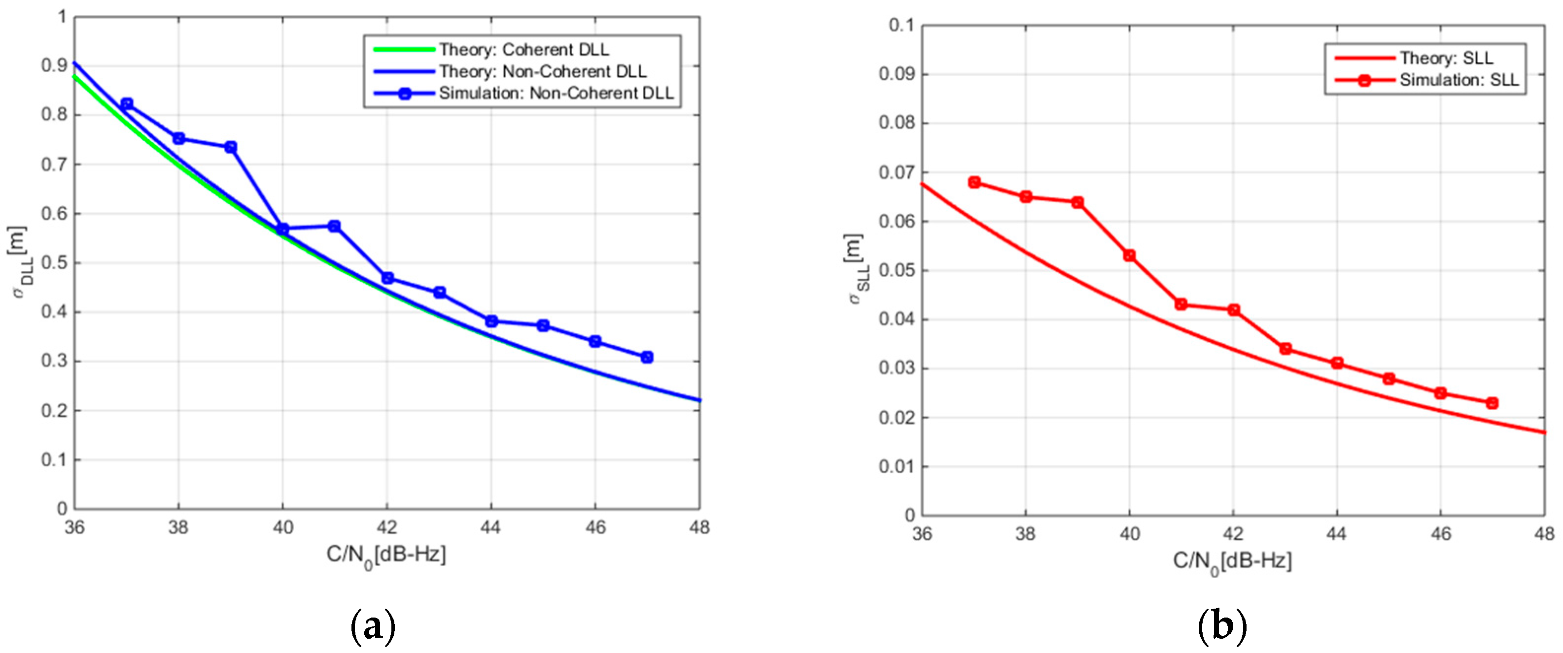
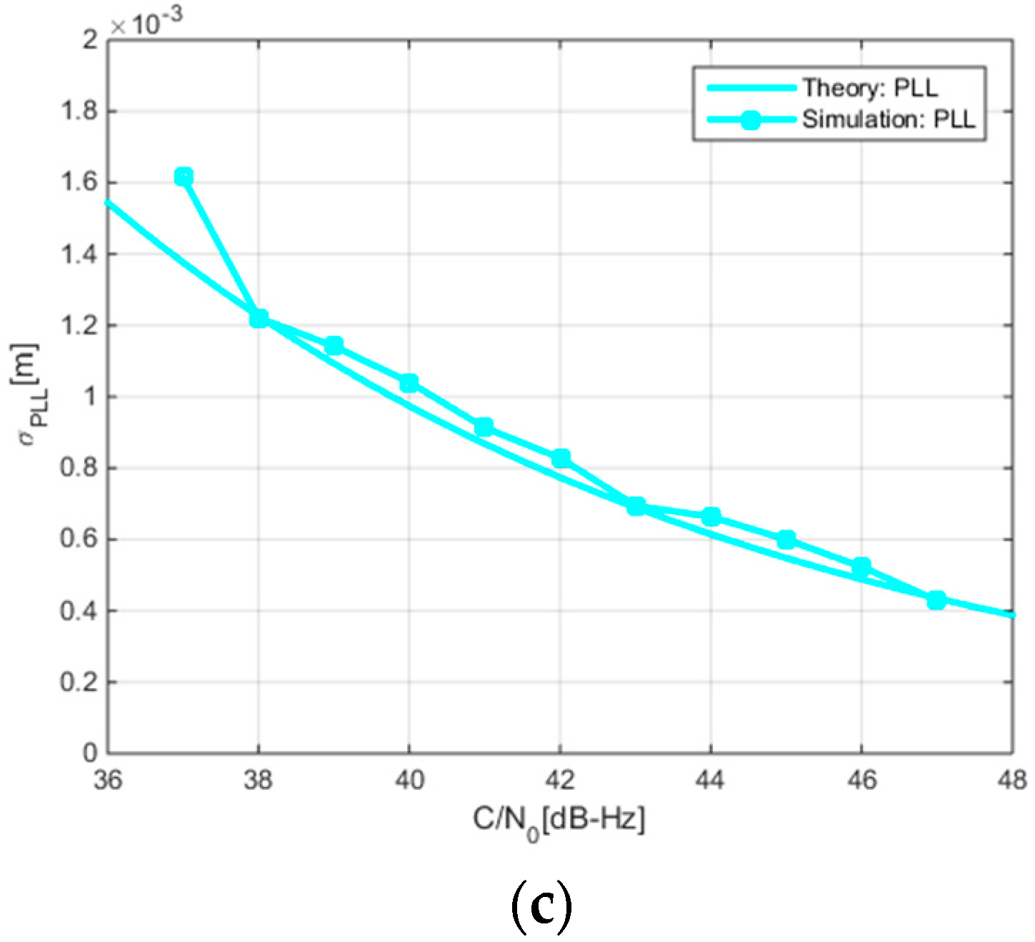
Figure 6 depicts the standard deviation of the code, subcarrier, and carrier tracking errors of the ASYM-DBT method while processing the B1-ADS signal. For the convenience of comparison, theoretically derived results are also presented in the same figure. Comparing SLL with DLL, the subcarrier noise error is one order of magnitude smaller than the code noise error. This is the result of the larger Gabor bandwidth of the B1-ADS signal. According to Equation (13), we can combine the subcarrier measurement with the code measurement to form a high-precision and unambiguous pseudorange measurement with centimeter-level accuracy. This high-precision pseudorange measurement is very helpful to rapidly determine the ambiguity of the carrier phase in Precise Point Positioning (PPP) or Real Time Kinematic (RTK) technology [
29,
30].
Figure 7 gives the thermal noise performance of DLL and PLL under three receiving modes. It must be noted that the horizontal axis in this figure is still expressed as C/N
0 calculated based on the power of the B1-ADS signal. From
Figure 7, it is obvious that the DLL noise performance of the B1-ADS signal is 3 dB better than that of B1I and B1C signals, and the PLL noise performance of the B1-ADS is also better than that of the other two signals. These results confirm that the ASYM-DBT method can effectively combine the B1I and B1C signals to obtain the power gain of the B1-ADS signal. It is worth mentioning that
Figure 7a shows that the DLL noise performance of the B1I and B1C signals are almost the same. The reason is that the improved ranging performance brought by the steeper ACF of B1C signal is offset by the stronger power of the B1I signal relative to the B1C pilot signal.


