1. Introduction
The technology of multi-group ultrasonic sensors that consist of lots of piezoelectric elements and various scanning patterns of an ultrasonic phased array (UPA) have recently attracted widespread attention in the non-destructive testing area [
1,
2]. The UPA produces a series of the ultrasonic waves controlled by the amplitudes and phases of the electrical pulses to excite a series of elements of the sensors. The waves can easily penetrate inside some materials by adjusting their radiation direction to synthesize flexible and rapidly focused scanning ultrasonic beams. The parameters of beams such as angles, focal distances, and focal spot sizes can be readily tuned with suitable software. Therefore, the beams can be used to detect defects that possibly occur at random positions of the materials [
3,
4,
5,
6].
To increase the focusing ability, a UPA instrument is often equipped with multiple ultrasonic sensors to collect the ultrasonic echo data from different directions. Each sensor can work in one or more groups so that a variety of scanning modes are generated [
7,
8,
9,
10], which can be called as a multi-group scanning, and each group scanning includes many focused beams. Hence, the number of the sensors and the scanning groups are two important factors to determine detection accuracy [
11,
12], such as size, location, and orientation of defects. For example, Song et al. verified that a large-aperture hemispherical phased array can restore a sharp focus and maximize acoustic energy delivery at target tissue [
11]. Regardless of the orientation of individual focused beams, the multiple focused beams can change their focal depths and sweeping angles through the phase interference. As a consequence, it is possible to precisely detect the position and the size of defects by means of increasing the number of the sensors, the scanning groups, and the focused beams. However, this strategy will in turn significantly increase the amount of scanning data in the process of the defect detection, which makes these data difficult to be transmitted to a peripheral through a single (or small quantity) high-speed serial bus, and subsequently produces an ultrasound image.
Each focused beam often brings different sampling rates and sizes of data stream. During the transmission process, different data streams compete against each other to gain access to the unique high-speed serial bus. An excellent transmission scheduling algorithm should allow all the data streams to be transferred to a peripheral without any blocking in a serialized way. Otherwise, the data streams would be blocked or severely delayed. Therefore, it is very desirable to design an effective algorithm to serially transmit a great amount of the data streams. Several well-known scheduling algorithms have been proposed, such as Time Division Multiple Access (TDMA) [
13] and Round Robin (RR) [
14]. The verification, analysis, and comparison of the two algorithms were presented in literature [
15], which proves that the TDMA strategy based on the fixed allocation of a time slot to each master process may lead to important latencies as a time slot, and the RR protocol allows any unused slots to be reallocated to a master process to provide higher bandwidth. Unfortunately, the process of the reallocation will make the time slice resources more fragmented, and increase the complexity of the scheduling algorithm. Multiple examples of implementation for the scheduling algorithm are available in the open literatures [
16,
17,
18,
19,
20,
21,
22,
23]. Srinivasan et al. designed a self-configuring scheduling protocol for ultrasonic sensor systems by using an algorithm of the timeslot allocation, which simplified the deployment of the present detection system [
16]. Long et al. proposed a time-division-multiple-access-based energy consumption balancing algorithm for the general k-hop wireless sensor networks, where one data packet is collected in one cycle, and the results demonstrated the effectiveness of the algorithm in terms of energy efficiency and time slot scheduling [
19]. However, although these strategies can effectively improve the efficiency of the data transmission, they increase the complexities of both hardware and software, and their application scopes are limited, which makes such strategies not suitable for UPA of the multi-group sensor scanning system because of limited hardware and software resources and high real-time request.
FPGA, which is short for the term field programmable logic gate array, has the characteristics of static system repeatable programming and dynamic system reconfiguration, so that hardware can be modified programmatically, and FPGA also is a special kind of ASIC with the advantages of parallel processing, high speed and flexibility. In this paper, we used a series of FIFOs as high-speed caches and cache times as weights to propose a novel FIFOs and bandwidth-sharing scheduling (MFBSS) algorithm of the data transmission, where the lengths of the FIFOs are achieved by a series of multivariate equations. Actually, the algorithm shows many advantages such as real-time and high efficiency when it is implemented by FPGA technology. As far as the UPA system of the array sensors is concerned, we designed a data stream transmission scheduling mode based on the MFBSS algorithm, with which reading operations among all the FIFOs shares a fast reading bus without time slot waiting when the reading bus switches between any two FIFOs. Hence, such algorithm gives the maximum bandwidth utilization ratio and improves the real-time performance of the UPA instruments with minimal consumption of time and space resources.
In
Section 2 of the paper, we will describe the data transmission of ultrasonic scanning for UPA [
24,
25,
26]. In
Section 3, we will study scheduling mechanism of the MFBSS algorithm for the data transmission.
Section 4 will describe the results of implementation for the scheduling algorithm by FPGA technology. Finally,
Section 5 will summarize the research to derive the conclusion.
2. Multi-Group Sensor Scanning Ultrasonic Data Transmission
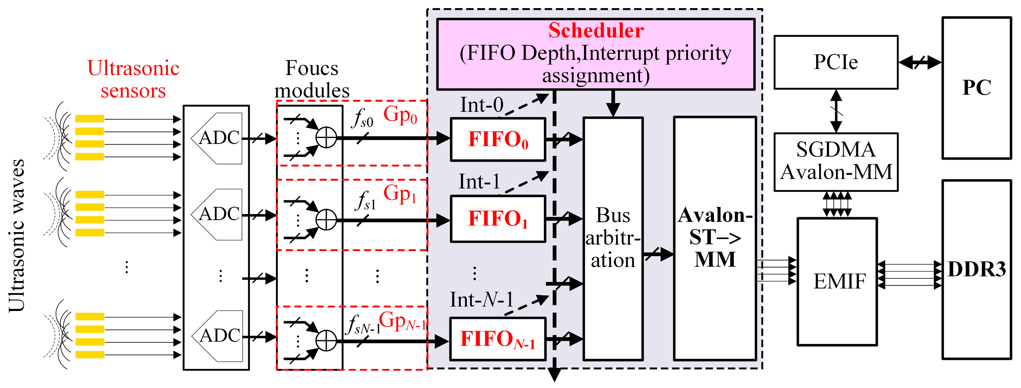
Figure 1 shows the UPA data transmission framework of the bandwidth-sharing with multiple scanning patterns [
7,
8,
9,
10]. In order to realize the optimal sampling of the UPA’s echoes, different frequency echoes should be digitized with different sampling frequencies [
27,
28,
29]. A sensor with a frequency of
fp Hz produces ultrasonic echoes with the same frequency after excitation, and thus the sampling frequency is
fs = K ×
fp Hz (K is a scaling factor, and K ≥ 2). Hence,
N-group sensors can form
N-group scanning patterns, generating
N sampling frequencies (
fs0 ~
fsN−1, where 0 and
N − 1 represent the numbers of sampling) and forming
N focusing beams with specific speeds and sizes.
As shown in
Figure 1, the data of various scanning groups such as Gp
0, Gp
1, …, and Gp
N−1 produced from the ultrasonic sensors are written into FIFO
0, FIFO
1, …, FIFO
N−1, respectively, which are cached by a DDR3 through the Avalon bus in the bandwidth-sharing way [
30]. Then, the data from the DDR3 are transmitted to the host computer through the PCIe bus [
31,
32]. The entire data transmission process is controlled by a bandwidth scheduler, which is composed of a controller with all the FIFOs’ lengths and a reading arbiter, and usually runs the following scheduling algorithms such as First Come First Serve (FCFS), TDMA and Equal Time Slice Polling Scheduling (ETSPS) based on the principle of the RR scheduling which will be mentioned in
Section 4, and so on. This paper will adopt the MFBSS algorithm to realize reading operations from every FIFO without time slot waiting through adjusting the lengths of FIFOs, timings of the reading and writing, and priority of the interrupts. Therefore, this algorithm can not only ensure the data transmission synchronization but also maximize the bandwidth utilization in all groups, which is readily implemented by FPGA technology with parallel processing.
3. Data Transmission Scheduling Mechanism of MFBSS Algorithm
3.1. The principle of the Maximal Bandwidth Utilization
To evaluate the utilization ratio of the data transmission bandwidth of the N-group scanning in the multi-input and single-output interfaces of the UPA system, the following requirements are satisfied:
Data transmission models Gp(n), n = 0, 1, …, N − 1 are independent from each other and have identical distributions for every group.
The sum of the data bandwidth [
] of all the groups and the sum of the memory bandwidth (
) and the sum of the transmission bandwidth (
) of the peripheral need to satisfy the following inequality:
The defined parameters of the
N-group scanning and the
N FIFOs caches are listed in
Table 1. The writing bandwidth and the reading bandwidth of the
nth FIFO
n are
VW(
n) [
VW(
n) =
fsn × ΔB] and
VR bit/s, respectively. The sum of the writing bandwidth of all the FIFOs [
] should equal to the sum of the transmission bandwidth of the
N-group scanning data [
], i.e.,
=
. Likewise, the sum of the reading bandwidth (
VR) of all the FIFOs should equal to the sum of the transmission bandwidth of the DDR3 bandwidth (
), i.e.,
VR =
. When the Equation (1) becomes an equality, the maximum bandwidth utilization ratio is achieved, i.e., the single-output bandwidth equals to the sum of the multi-input bandwidths from the FIFOs. Consequently, the mathematical principle of the maximal bandwidth utilization ratio can be written as Equation (2).
3.2. Realization of the Maximal Bandwidth Utilization Ratio
According to Equation (2), the mathematical model of the N FIFOs’ length functions of L(i), i = 0, 1, …, N − 1, [L(0) ≤ L(1) ≤ … ≤ L(N − 1), FIFO0, FIFO1, …, FIFON−1] can be described as follows:
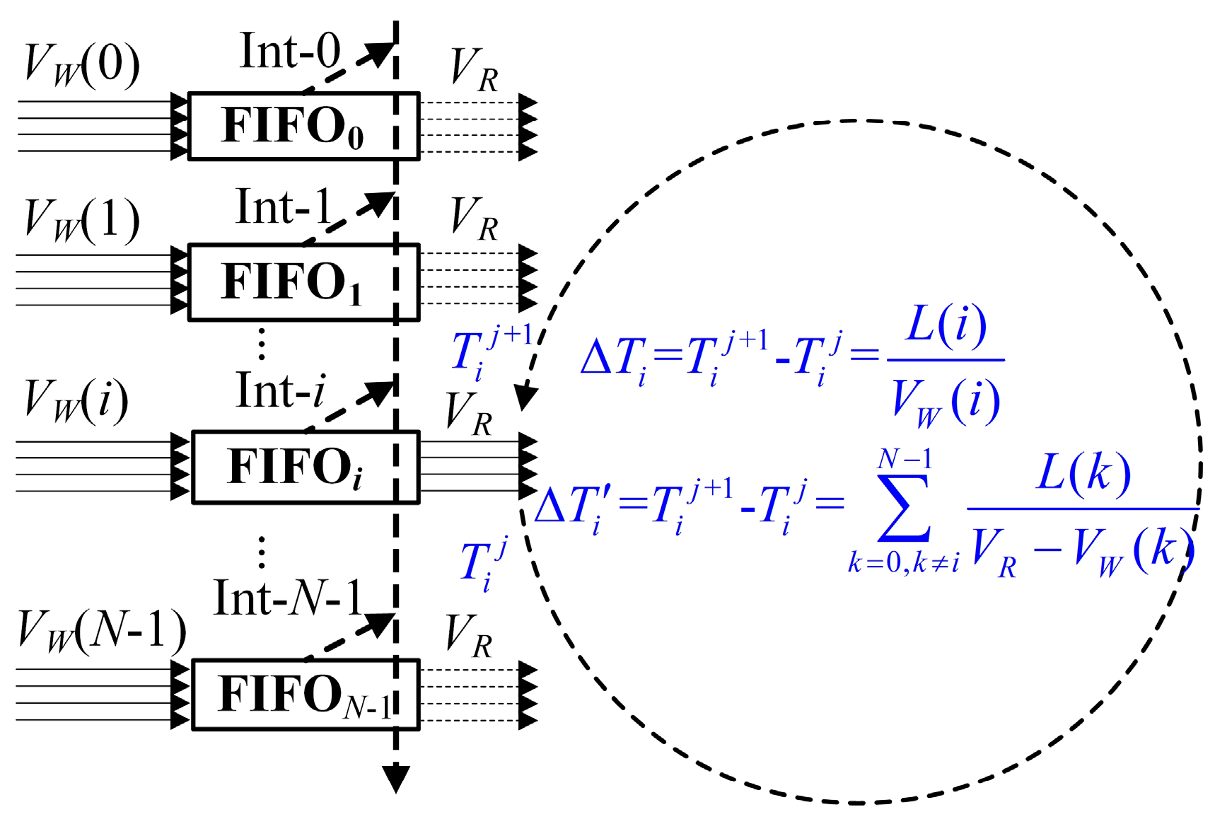
Assuming that at the moment , when the FIFOi is read until empty, the reading operation of the FIFOi will be disabled.
At the next , when the FIFOi is full and the amount of the data is L(i) (i = 0, 1, …, N − 1), the reading operation of the FIFOi will be enabled.
When the FIFO
i transfers from empty to full (where the consumed time is Δ
Ti =
−
and a reading interrupt is produced), the FIFO
i will gain access to the reading of the Avalon bus. During this process, the other FIFOs with the number of 0, 1, …,
i + 1,
i + 2, …,
N − 1 have also transferred from full to empty with the consumed time of Δ
T'i =
. The time slot transition diagram of the
N FIFOs reading operations is shown in
Figure 2. Because Δ
Ti = Δ
T'i, i.e., Δ
T'i − Δ
Ti = 0,
i = 0, 1, …,
N − 1, the mathematical equations of the N FIFOs’ length functions of
L(
i),
i = 0, 1, …,
N − 1 can be easily described in Equation (3).
where
L(
i) ≠ 0,
i = 0, 1, …,
N − 1 in Equation (3). A series of new variables are given in Equation (4) for the simplification of Equation (3).
Equation (3) is transformed into a matrix of Equation (5):
The matrix
is achieved by elementary row transformation, and then the triangular array is applied:
,
i = 0, 1, …,
N − 2,
fK(
x0) = −
K'0, and
can be done by using the following recursion:
According to Equation (4),
can be described as Equation (7).
For the
N-group scanning of the UPA system, when
i =
N, according to the Equation (2),
VR =
, and
=
. The matrix
can be transformed to
through the primary row transformation:
Because the rank of the matrix and the rank of the matrix have the following relation , Equation (5) has an infinite number of the solutions, and because ⇔, and the solutions can be expressed as follows:
fK(
xi) ×
L(
i) + (
Ki+1 −
fK(
xi+1)) ×
L(
i+1) = 0, (
i = 0, 1, …,
N − 2), and
L(
i) =
(
i = 0, 1, …,
N − 2), and
L(
i) can be further deduced forward:
Substituting the expression of
fK(
xi+1) from Equation (7) into Equation (8). The values of
L(
i),
i = 0, 1, …,
N − 1 are obtained, as shown in Equation (9):
when Equation (9) is multiplied by a term of
, a set of fundamental solutions
to the equations of
will be obtained:
Therefore, the solutions to the equations of can be expressed as (α∈R+). The length function of L(i), i = 0, 1, …, N − 1 of the FIFOs has a proportional relation, as showed in Equation (10).
Equation (10) can be used to describe the most critical conclusion to realize the MFBSS algorithm, which shares the transmission bandwidth for the N-group scanning of the UPA system. Therefore, according to the ratios of the FIFOs’ lengths, i.e., the cache time of each FIFO, the reading operation can be switched among each FIFO without time slot waiting, thus maximizing the bandwidth utilization ratio.
When the algorithm is implemented by an FPGA, in order to make the consumed resources of the FIFOs minimal, the ratio of
L(0):
L(1):…:
L(
N − 1) can often be simplified to a series of the suitable integer ratios. In the system of the
N-group scanning and the
N FIFOs caches, if the sampling rate
fsn (
n = 0, 1, …,
N − 1, and unit is 100 MHz) of the
N groups linearly increases,
VR =
, and ΔB = ΔB
W = ΔB
R. The ratios of
L(0):
L(1):…:
L(
N − 1) of the FIFOs’ lengths are calculated from Equation (10), and the results are listed in
Table 2.
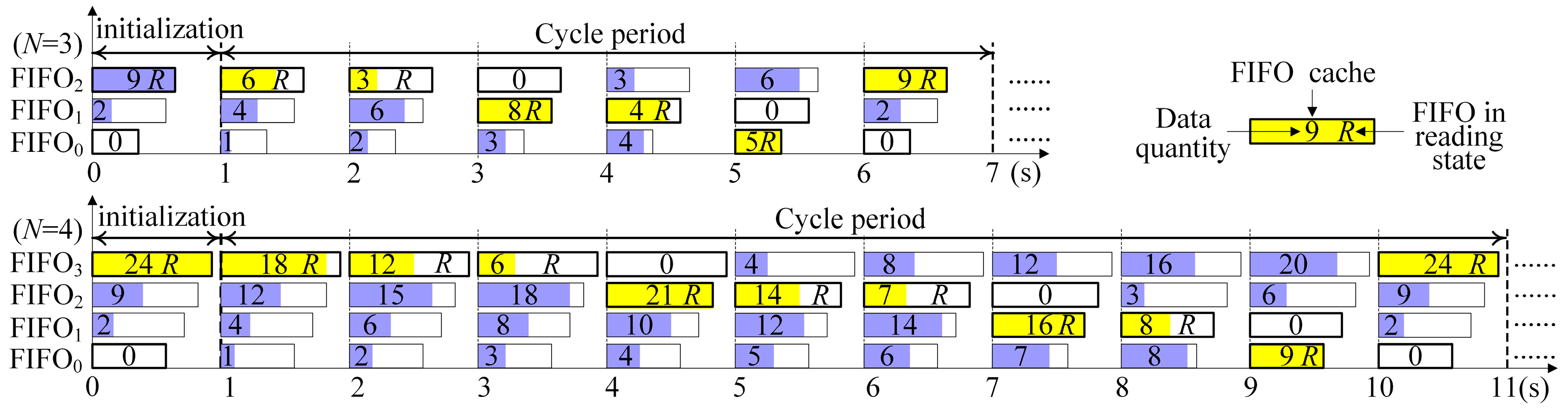
Figure 3 shows the time slot switching flow chart with the sharing reading bus of the
N-group scanning and the
N-FIFO caches (
N = 3 or 4). The horizontal axis represents the time (unit: s). In the initialization phase, the FIFO
N−1 caches the maximum sampling rate beam, which is filled with the length
L(
N − 1) data. Meanwhile, the other caches FIFO
N−2 ~ FIFO
0 are filled with the lengths [
L(
i) −
](
i =
N − 2,
N − 3, …, 1, 0), respectively. The working principle is described as follows:
When an FIFO is full, it will be immediately read until empty (the symbol R represents the reading state of the FIFO), and subsequently switches to the next FIFO without any time slot in the process of the data transmission. Likewise, when the next FIFO is just written fully, it will be read immediately. Therefore, the whole process is carried out in cycles without any delay, maximizing the utilization ratio of the data transmission bandwidth.
4. Implementation and Performance Evaluation of the Scheduling Algorithm
The scheduling algorithm is realized by using a UPA instrument (PA2000 model), which was made by Guangzhou Doppler Electronic Technologies Co., Ltd. (Guangzhou, China), and a Cyclone V GT FPGA Development Board made by Intel Corporation (Santa Clara, CA., USA) as the PCIe communication module with the PC. The UPA data are transmitted to the PC through the PCIe interface, and the multi-group scanning images are processed.
The UPA system with a work clock frequency (
fs) of 100 MHz is mounted with four sensors with four different frequencies (
fs) of 2, 2.5, 5, or 10 MHz, and thus the system can implement 4-group scanning patterns. The echoes of all the groups are up-sampled (
fs = 10 ×
fp) by using digital signal processing technology, and thus the actual sampling frequencies of
fs0 ~
fs3 become 20, 25, 50, or 100 MHz. The bit-width (ΔB) of the echo data is 8 bits, and both widths of the input (ΔB
W) and the output (ΔB
R) ports of the FIFOs are 64 bits.
Table 3 lists the parameters of the writing frequency [
VWf(
n)] and the reading frequency (
VRf) of the FIFO
n caches. Obviously,
VW(
n) equals to
VWf(
n) × ΔB
W, and
VR equals to
VRf × ΔB
R for this case, hence, the scheduling algorithm can be used to allow the 4-FIFO caches to realize sharing transmission bandwidth. The capacities of the FIFOs are
L(
n) × ΔB
W, and the length ratios of the FIFO caches can be calculated from Equation (10), i.e.,
L(0):
L(1):
L(2):
L(3) = 14:17:29:38. As listed in
Table 3, the value of
VRf is calculated to be 24.375 MHz, but it is relatively easier to implement the value of
VRf = 25.0 MHz (
VRf =
fs/4 = 25.0 MHz ≈
V'Rf) by the FPGA than the value of
VRf = 24.375 MHz, and thus we design the value of
VRf = 25.0 MHz for the experiment.
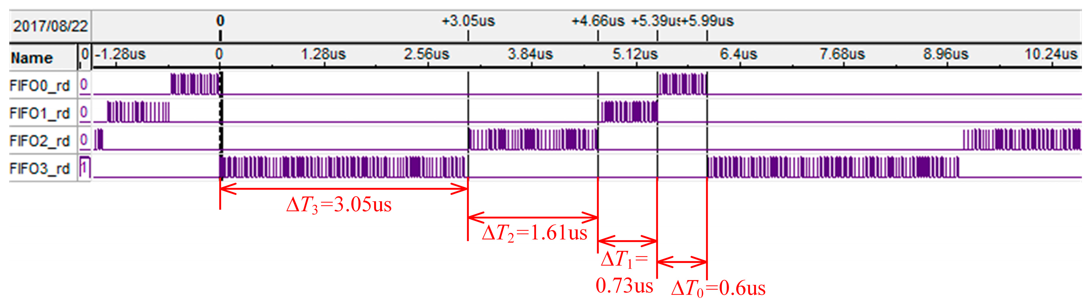
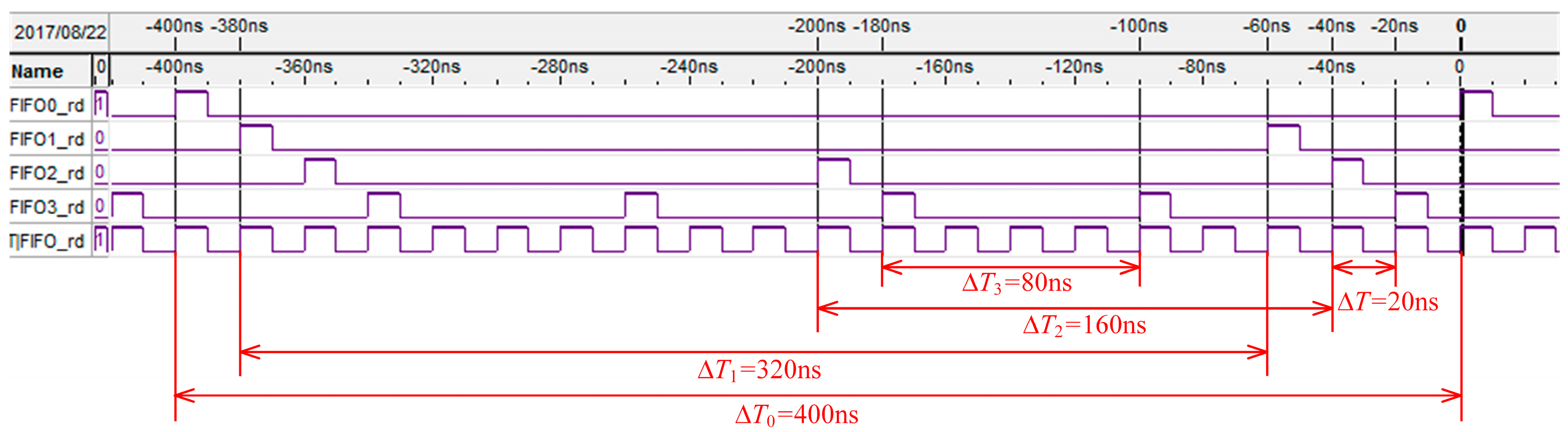
Figure 4 shows the 4 FIFOs reading timing waves of the MFBSS algorithm from Signaltap, and a soft oscilloscope is used to observe FPGA internal signals. The signals of FIFO0_rd ~ FIFO3_rd respectively control the reading operation of the 4 FIFOs, allowing it to enable output data in a time slice polling way. The times for reading the 4 FIFOs until empty are Δ
T0 ~ Δ
T3. The variables of Δ
T0:Δ
T1:Δ
T2:Δ
T3 have the following relation:
All the FIFOs are readed in turn until empty in every cycle. The sum of data (DW−sum) for writing into the FIFOs and the sum of data (DR−sum) for reading out from the FIFOs are given by the two formulas and , respectively. As a result, the experimental results show that DW−sum equals to DR−sum, which meets the relation of Equation (2), and also agrees well with the theoretical analysis.
In the
N-group scanning system, the bandwidth utilization ratio
of the MFBSS algorithm can be expressed by Equation (11):
Therefore, in the experiment, when
N = 4, the utilization ratio
of the MFBSS algorithm used in the UPA system can be calculated by Equation (12):
The ETSPS scheduling algorithm based on the equal allocation of a time slot to each task. As compared with the MFBSS algorithm in this work, the ETSPS scheduling algorithm has four characteristics: (i) The lengths of all the FIFO
i (
i = 0, 1, 2, …,
N − 1) are the same as each other, i.e.,
L(0) =
L(1) = … =
L(
N − 1). (ii) All the time slice resources of the reading operation of the
N FIFOs are also equal to each other. (iii) All the FIFOs have the reading speed (
V'Rf) which is equal to the maximum of the writing speed [
VWf(
i)], same as that of the individual FIFO, i.e.,
V'Rf = max[
VWf(
i)],
i = 0, 1, …,
N − 1. (iv) When the FIFO
i (
i = 0, 1, 2, …,
N − 1) is filled by writting, the reading operations of the FIFO
i will be immediately performed. Therfore, the general utilization ratio of the bandwidth-sharing transmission with
N-group scanning of the UPA system can be calculated by Equation (13):
For N-group scanning data stream with bandwidths {VW(0), VW(1), …, VW(N − 1)} (unit: Byte/s), we use the FPGA technology to implement the MFBSS algorithm together with the the traditional ETSPS scheduling algorithm, and analyze their bandwidth utilization ratios and . For example, the FPGA (Arria-II EP2AGX65DF29I5) with a work clock frequency of fclk = 100 MHz. So, it is easy to produce the clock frequencies such as F1 = {1, 2, 3, …, fclk } and F2 = {fclk/100, fclk/99, fclk/98, …, fclk/1} (unit: MHz) by using the clock fclk by Digital Phase Locked Loop technology.
The MFBSS algorithm. According to Equation (11), the theoretical value of the shared output bandwidth is
or (). The actual value of the shared output bandwidth is , which satisfies the following conditions: , F1 or F2, and the value of is minimized. For instance, when = 24.375 HMz, and = fclk/4 = 25 MHz, and thus the actual bandwidth utilization ratio is which equals to 97.5%.
The ETSPS algorithm. According to Equation (13), the larger the value of max(
VWf(
i)) is, the smaller the value of
is. The smaller the value of max(
VWf(
i)) is, the larger the value of
is. So, when the value of
equals to
, i.e.,
VW(0) =
VW(1) = … =
VW(
i) = … =
VW(
N − 1), the maximum theoretical value of
can be expressed by Equation (14).
when the value of max(
VWf(
i)) is close to
, i.e.,
, the minimum theoretical value of
can be expressed by Equation (15).
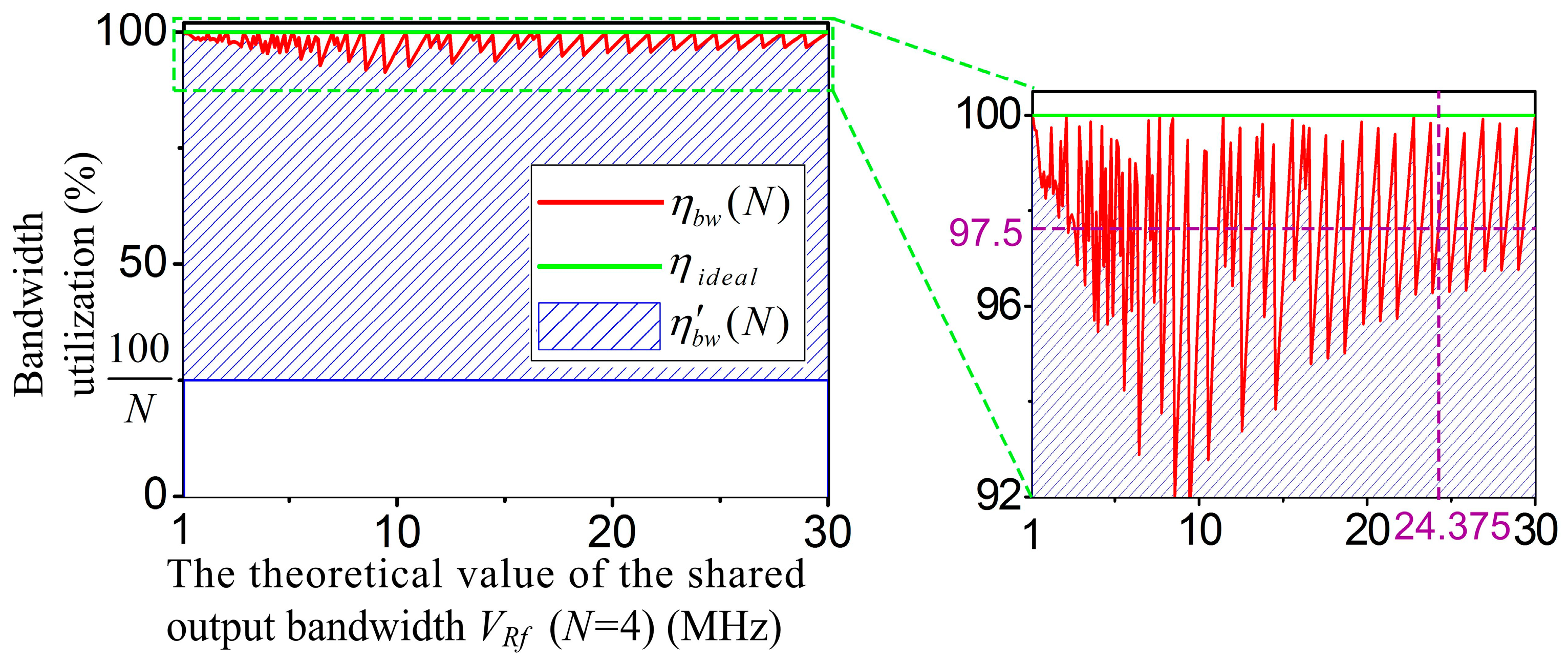
Figure 5 shows the bandwidth utilization ratio curves of the two scheduling algorithms (cross axis: the theoretical value of the shared output bandwidth
VRf (
N = 4), and vertical axis: the bandwidth utilization).
and
are the bandwidth utilization ratios of the MFBSS algorithm and the ETSPS algorithm, respectively.
The symbols and represent the experimental and ieal values of the algorithm MFBSS, respectively. The results show that the value of is between 92% and 100%, for example, for the above experiment of 4-group scanning based on the MFBSS algorithm, when VRf equals to 24.375 MHz, equals to 97.5% and equals to 100%. Whereas the value of is relevant to the value of N, its value is between (100/N)% and . For N-group scanning patterns, only when all groups have the same bandwidth, equals to . Otherwise, would be much smaller than .
Similarly, we use FPGA to implement the traditional ETSPS algorithm with the same parameters in
Table 3, and collected reading timing waves of the 4 FIFOs by using Signaltap. As shown in
Figure 6, the signals FIFO0_rd ~ FIFO3_rd control the reading operation of the four FIFOs, and the time resources occupied by the signals are assigned by the signal FIFO_rd.
Assuming that the symbols
fFIFO_rd,
fFIFO0_rd,
fFIFO1_rd,
fFIFO2_rd, and
fFIFO3_rd represent the frequencies of signals FIFO_rd, FIFO0_rd, FIFO1_rd, FIFO2_rd, and FIFO3_rd, respectively, the following results can be easily obtained, as shown in
Figure 6:
fFIFO_rd =
= 50 MHz,
fFIFO0_rd =
= 2.5 MHz,
fFIFO1_rd =
= 3.125 MHz,
fFIFO2_rd =
= 6.25 MHz,
fFIFO3_rd =
= 12.5 MHz.
So, the utilization ratio of the data transmission with the 4-group scanning of the ETSPS algoritnm can be calculated by Equation (16):
As a consequence, the bandwidth utilization ratio of the MFBSS algorithm
reaches to 97.5% as shown in the inset of
Figure 5, while the bandwidth utilization of the ETSPS algorithm
is only 48.75%. The experimental results demonstrate that the MFBSS algorithm is efficient when used in the multi-group sensors scanning UPA system.


