New Textile Sensors for In Situ Structural Health Monitoring of Textile Reinforced Thermoplastic Composites Based on the Conductive Poly(3,4-ethylenedioxythiophene)-poly(styrenesulfonate) Polymer Complex


Abstract
1. Introduction
2. Experimental
2.1. Materials and Methods
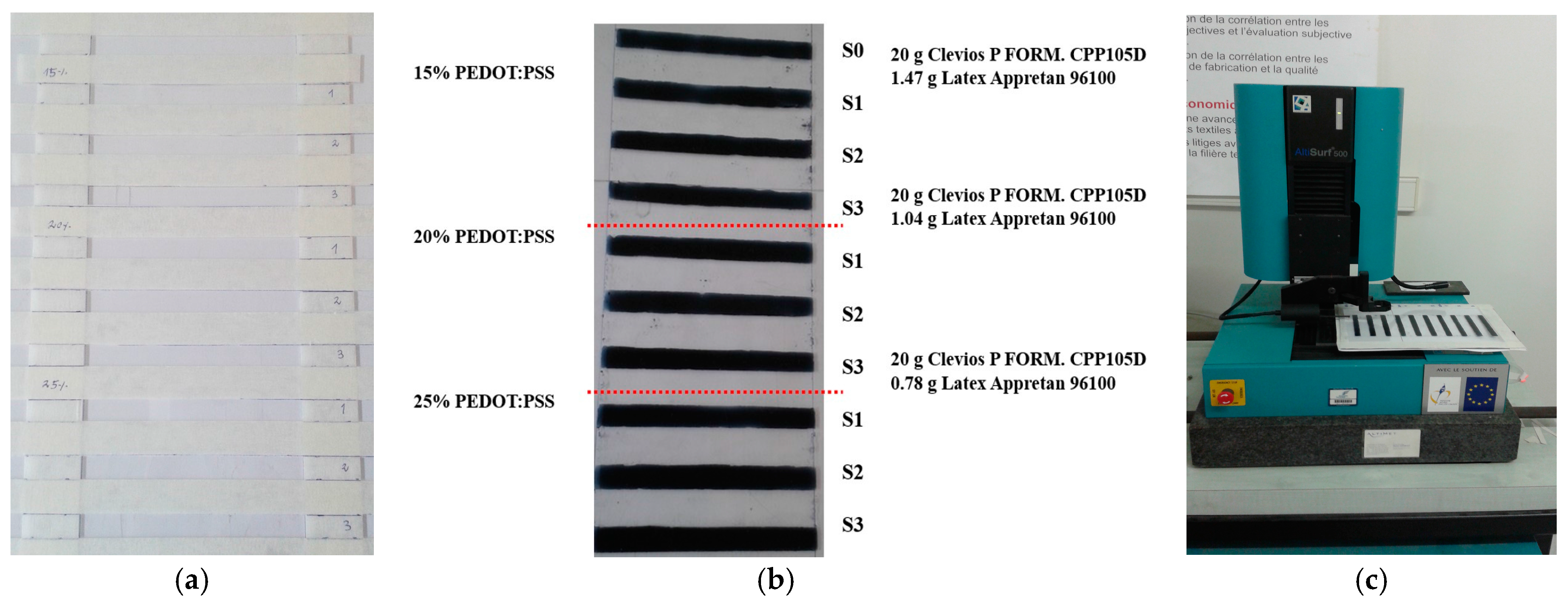
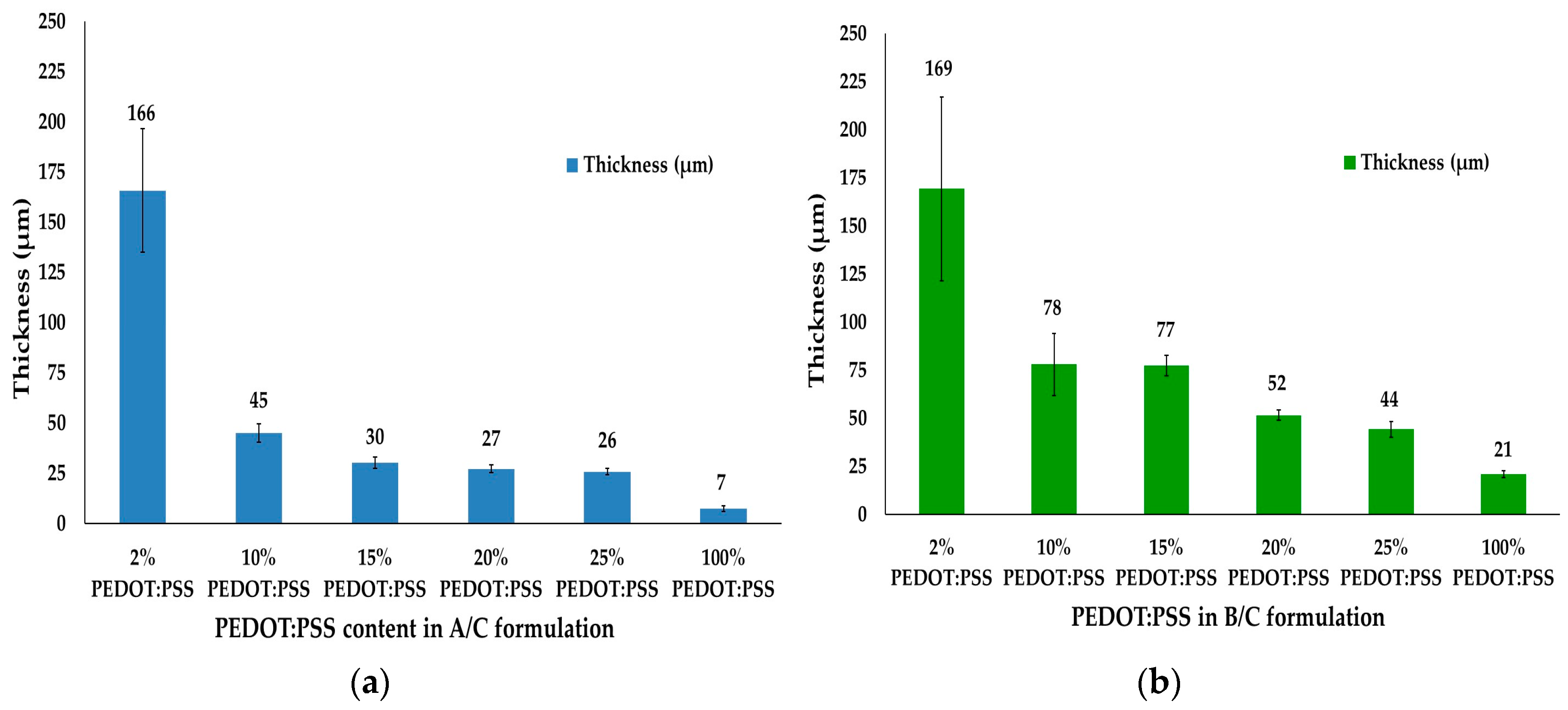
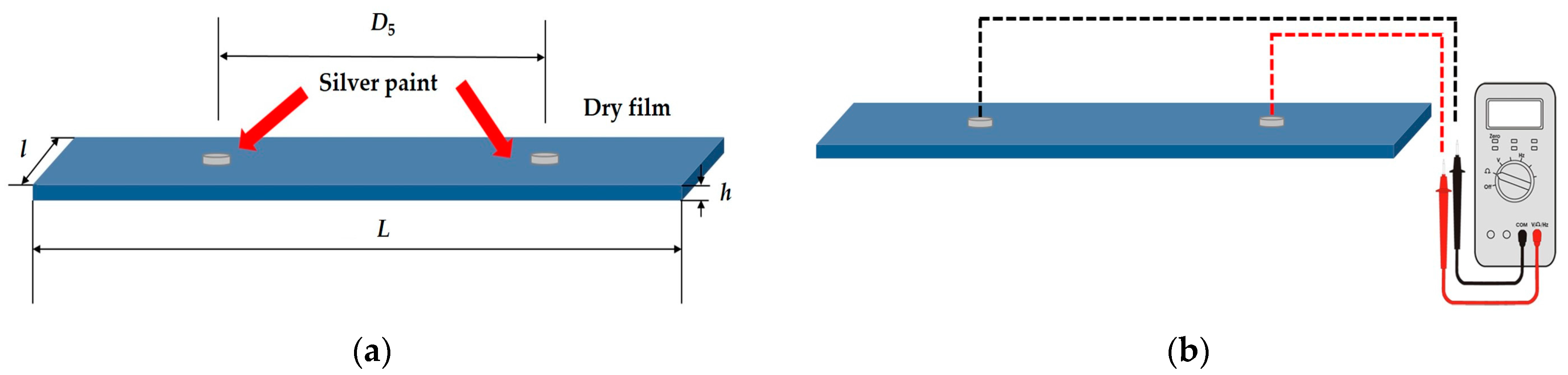
2.1.1. Electrical Resistance and Resistivity of Conductive Dry Films
- (i)
- The electrical resistances of 2–25% PEDOT:PSS conductive dry films increased when the track thicknesses decreased depending on the PEDOT:PSS content in the prepared A/C or B/C formulations. The electrical resistances also increased with the decrease in thickness for the neat PEDOT:PSS film compositions.
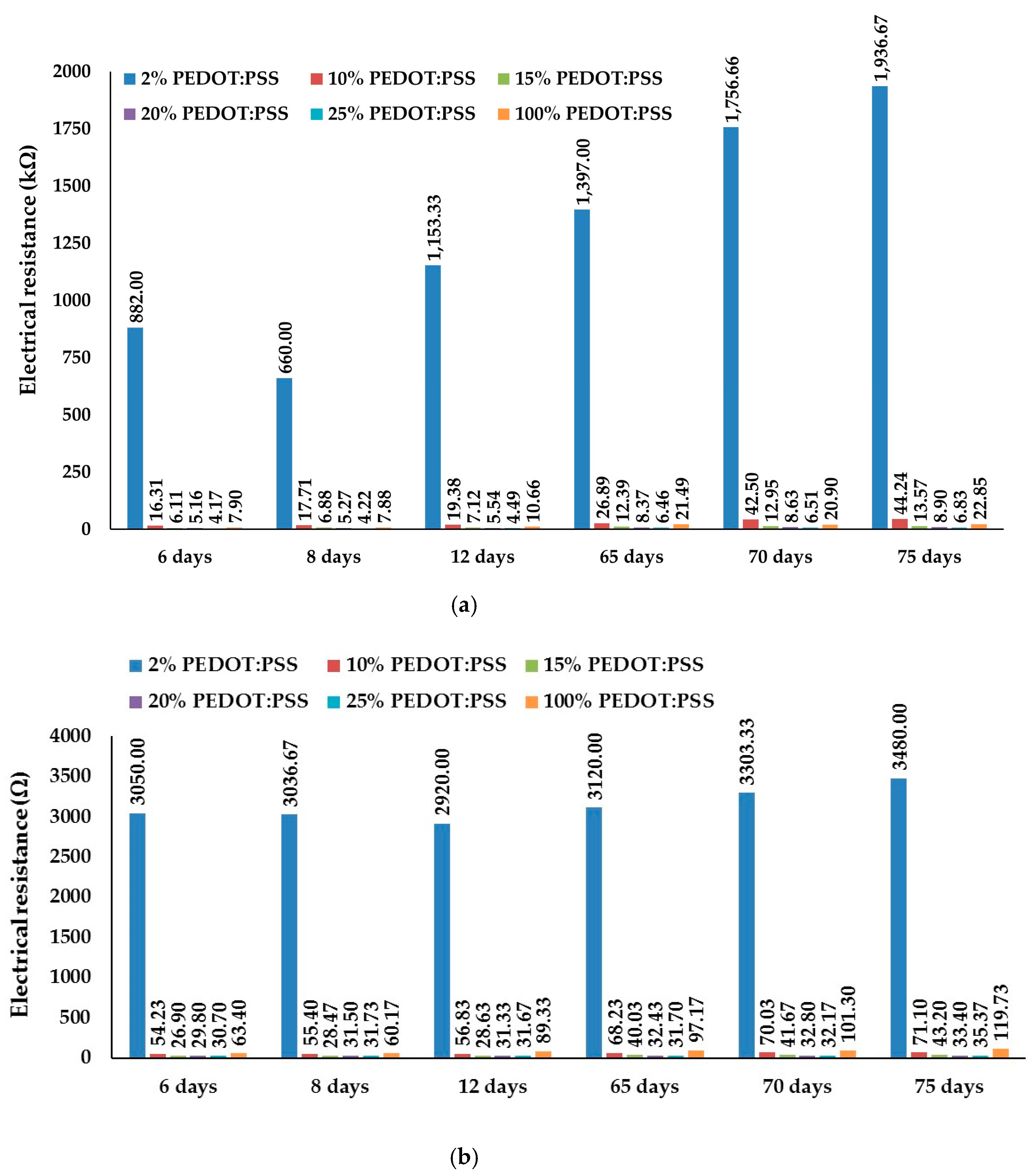
- (ii)
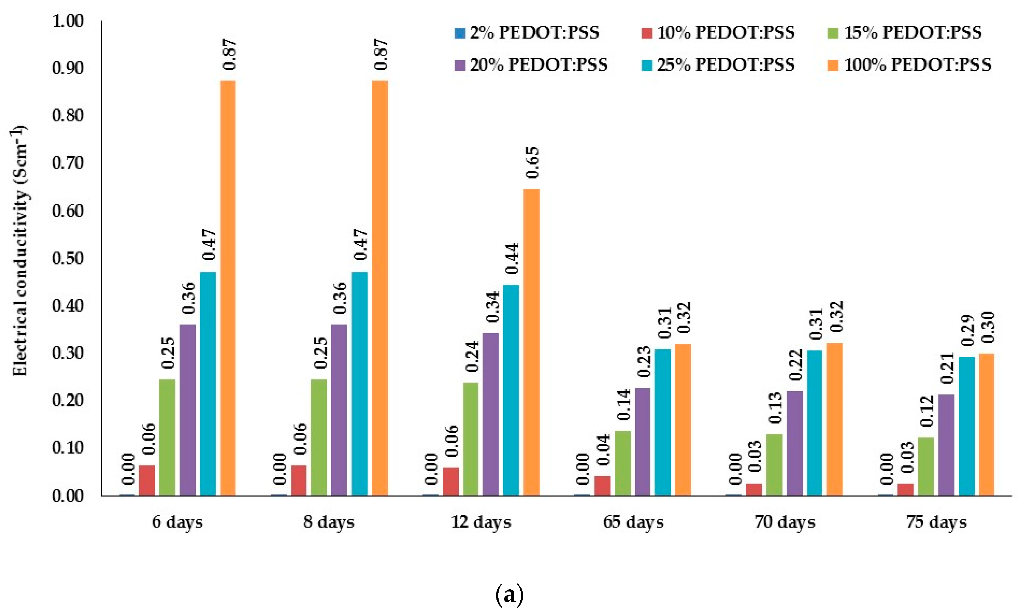
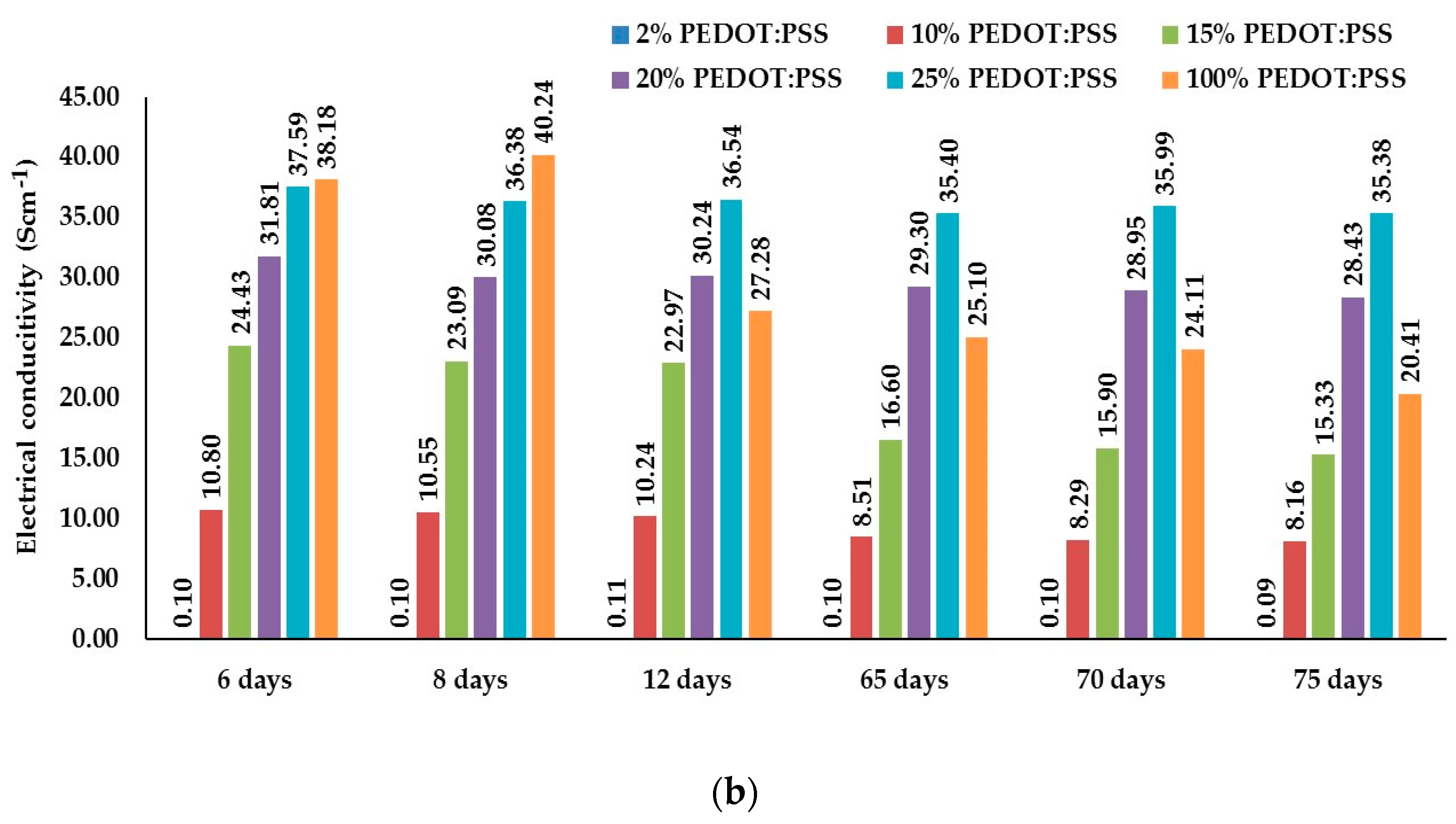
- The electrical resistances decrease with the increase in the PEDOT:PSS content in dispersions.
- (iii)
- Electrical resistance of dry films increased with time for 2–25% PEDOT:PSS formulations. There is an insignificant electrical resistance decrease afterwards:
- 8 days compared to 6 days for 2% PEDOT:PSS A/C dry film
- 8 and 12 days compared to 6 days for 2% B/C dry film
- 20 days compared to 12 days for 20% PEDOT:PSS A/C dry film
- 12 and 65 days compared to 8 days for 25% PEDOT:PSS B/C dry film
- (iv)
- Electrical resistance of conductive dry films also increased with time for 100% PEDOT:PSS dry films with insignificant electrical resistance decrease afterwards:
- 8 days compared to 6 days for 100% PEDOT:PSS A dry film
- 70 days compared to 65 days for 100% PEDOT:PSS A dry film
- 8 days compared to 6 days for 100% PEDOT:PSS B dry film
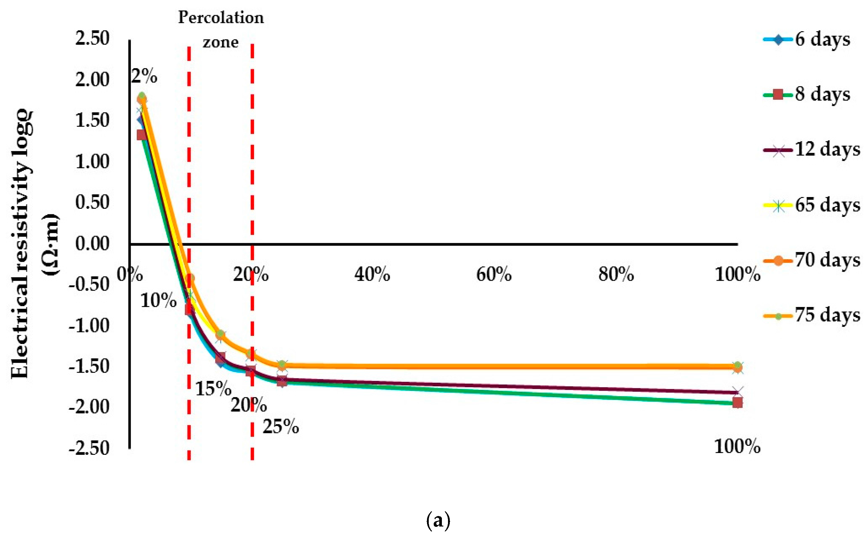
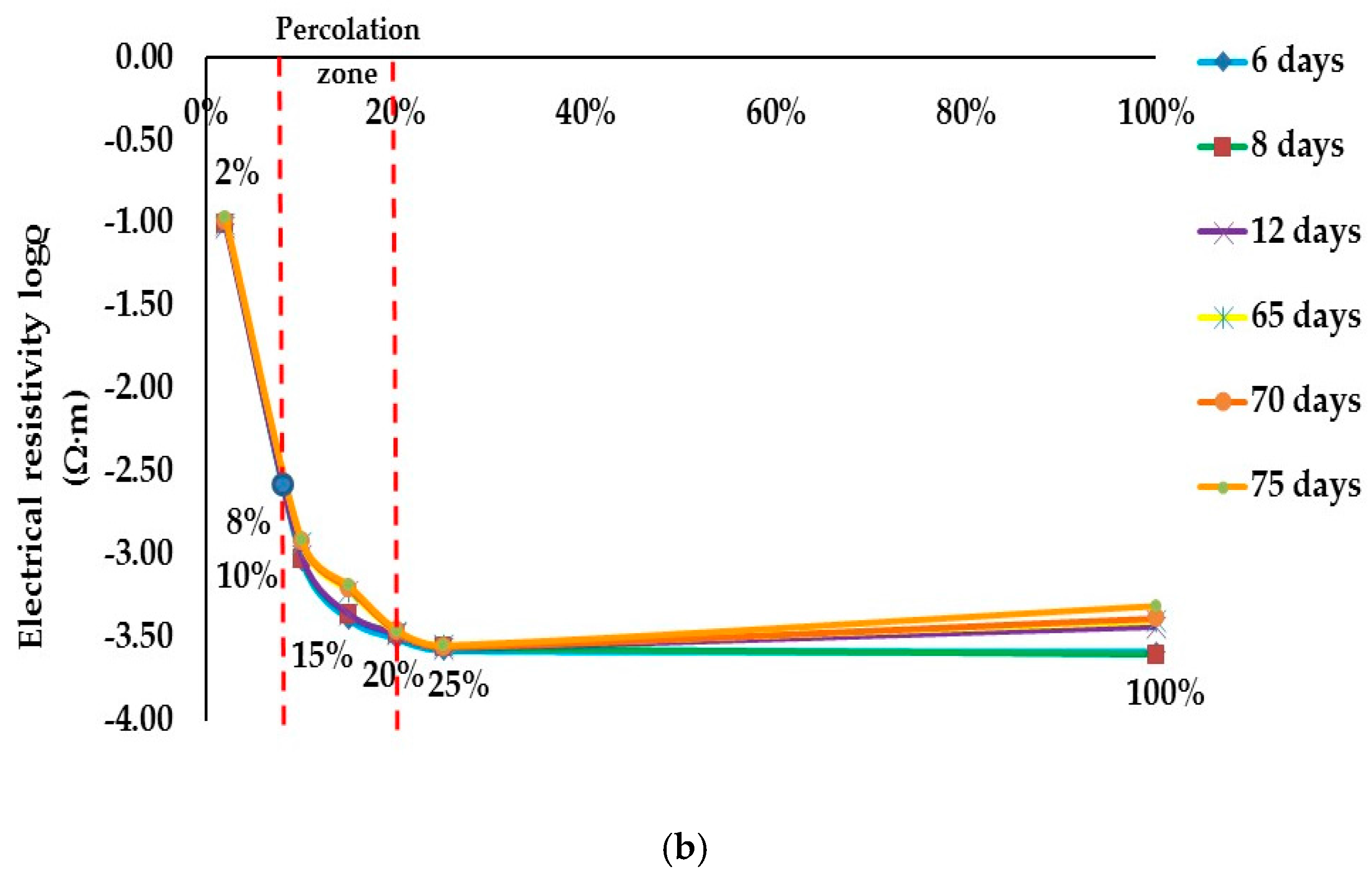
2.1.2. Percolation Threshold
2.2. Textile Sensors Production
3. Results and Discussion
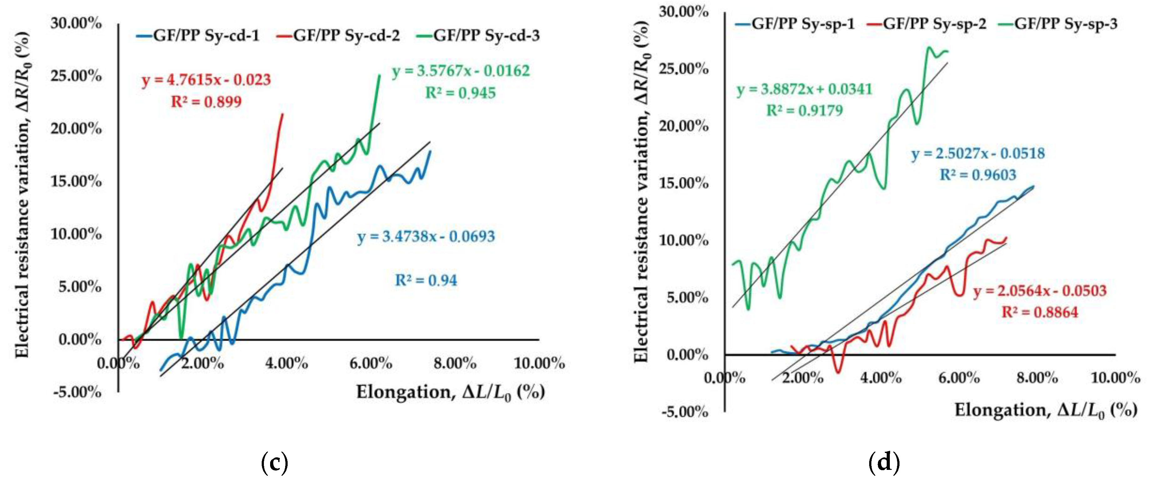
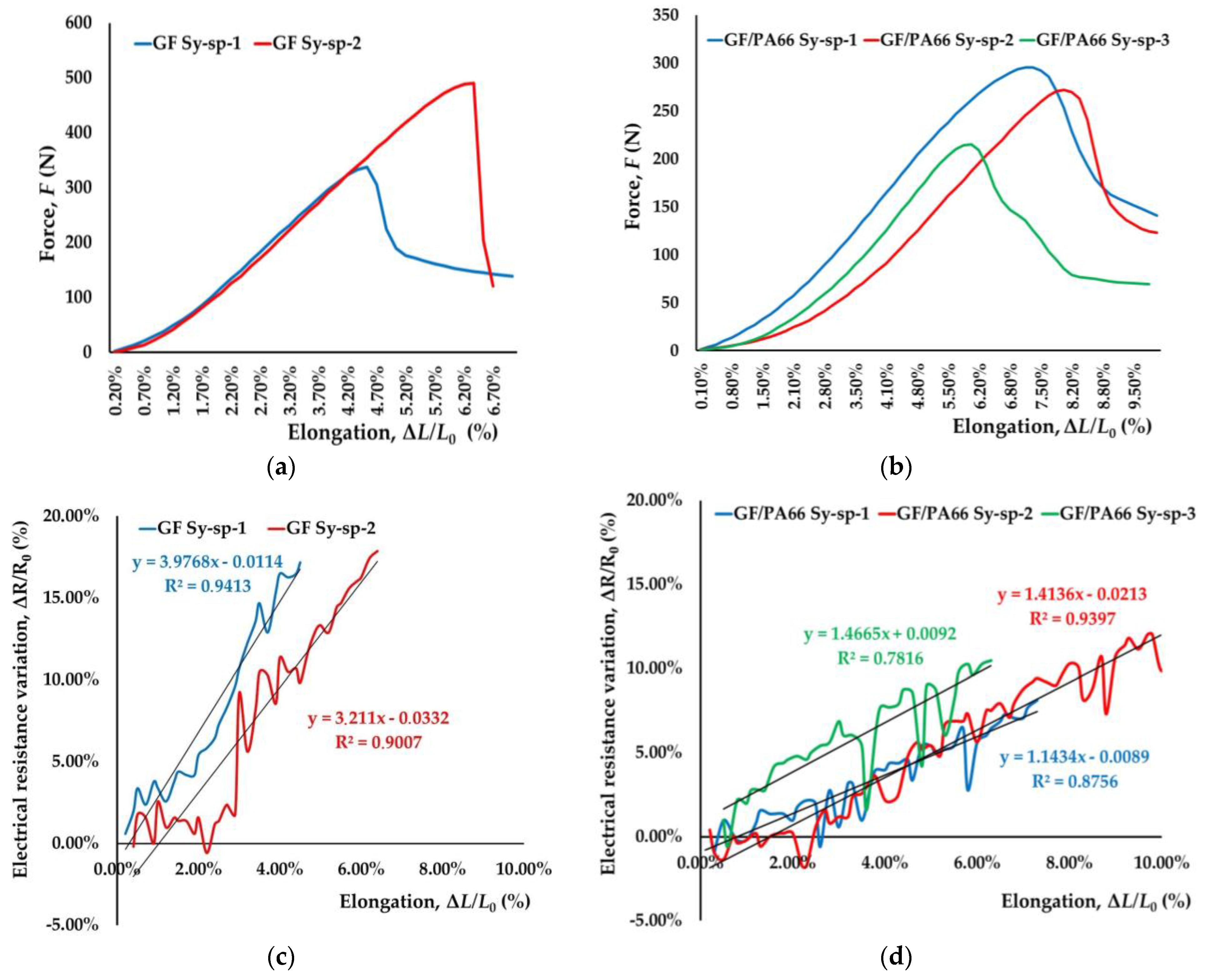
Electromechanical Properties of Textile Sensors
4. Conclusions
Acknowledgments
Author Contributions
Conflicts of Interest
Appendix A
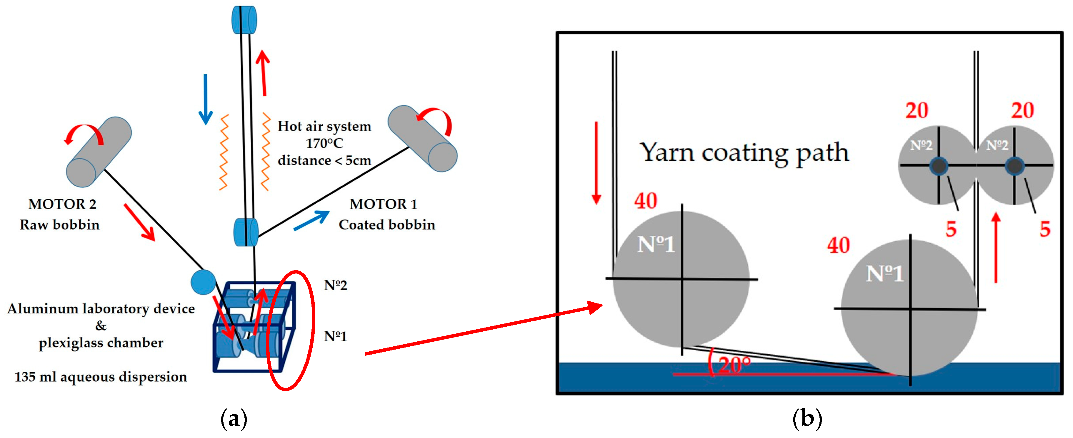
Appendix A.1. Roll to Roll Coating Method

Appendix A.2. Textile Sensors Preparation

- (i)
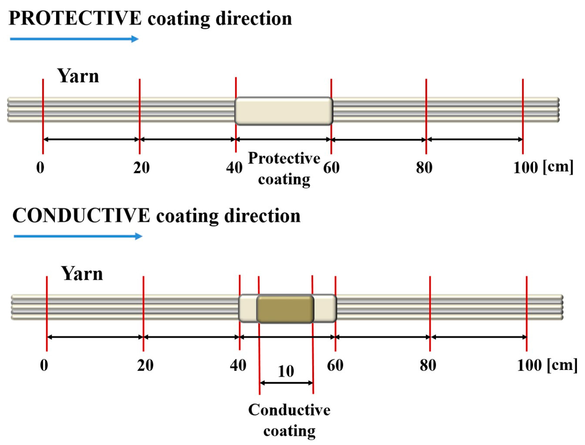
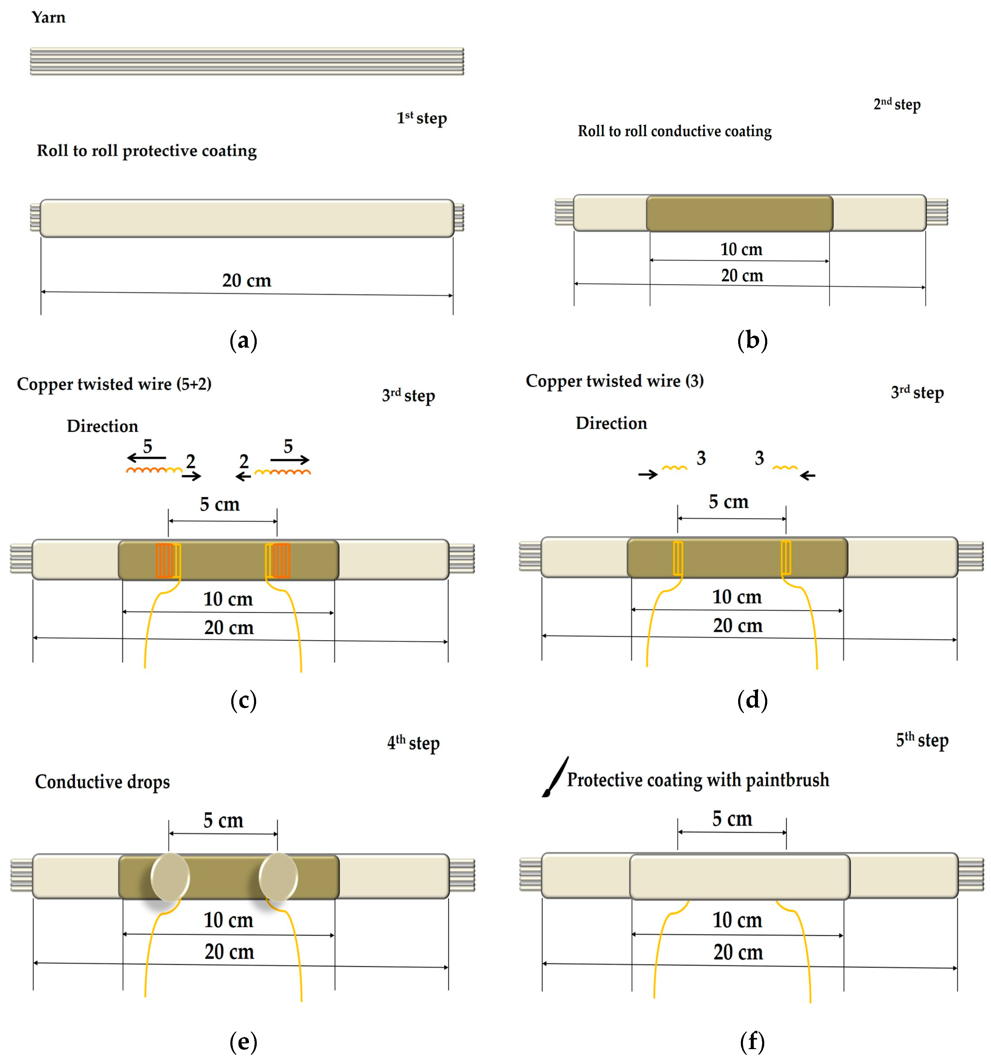
- The sole yarn was coated with protective coating, chemical C, (Figure A3a). One drop of fast-acting anionic wetting agent, NOVAROL DEL, chemical D, used for the treatment of cotton, wool and synthetic fibres was added in C-aqueous dispersion for the first protective coating to improve homogeneity of yarn coating and to increase the adhesion between the conductive coating and yarn as a following step for textile sensors production.
- (ii)
- After that, two conductive coatings, 8% PEDOT:PSS B/C dispersion, were applied according to the preliminary study as the optimum number of conductive coatings (Figure A3b).
- (iii)
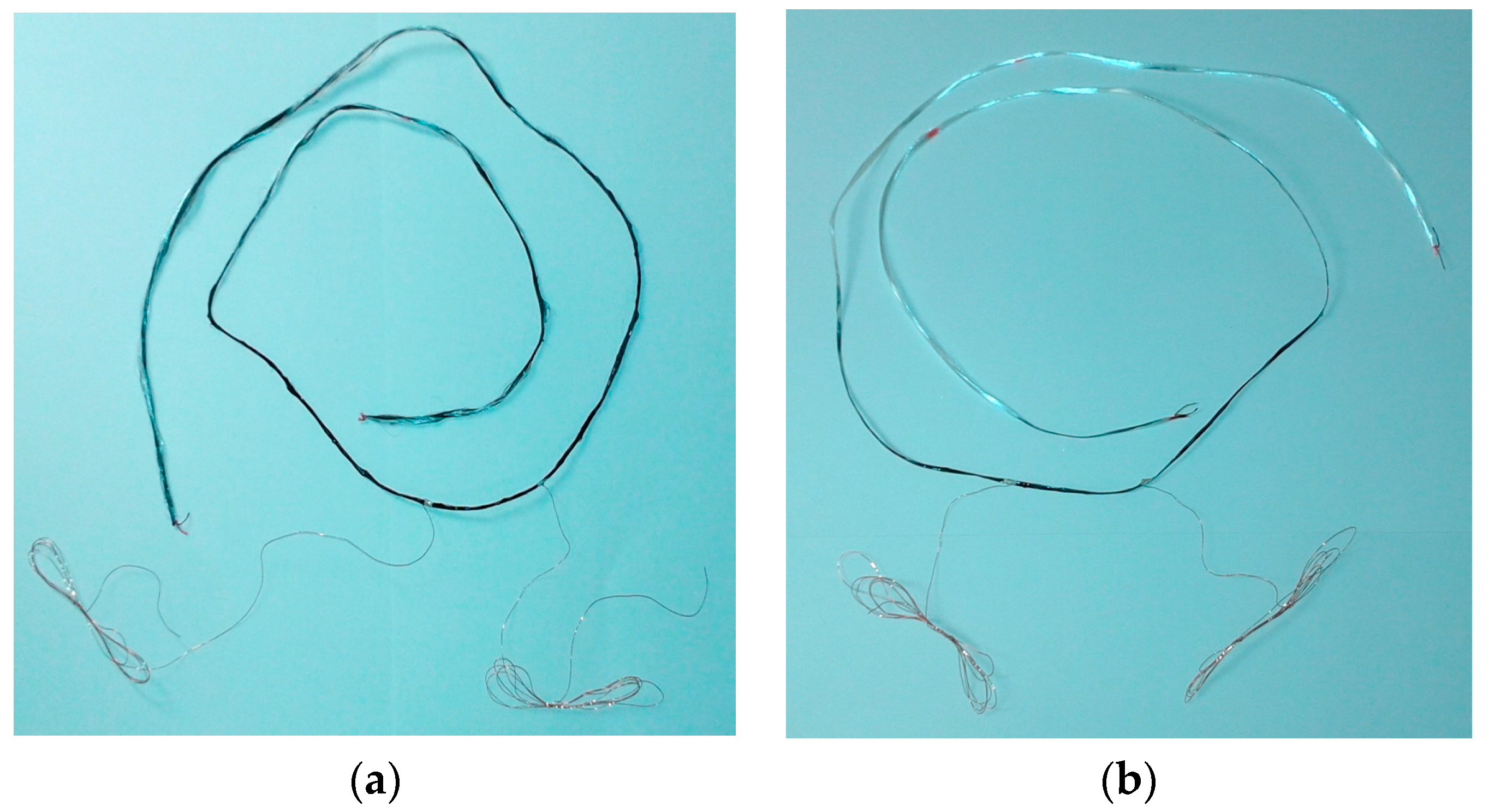
- Copper wires were twisted around conductive coated yarn, 5 rounds in one direction and 2 in the opposite direction, to avoid electrical disturbance due to inductivity and capacity of the connections (Figure A3c), or 3 rounds in one direction (Figure A3d), before the last protective coating and placed at the distance of 5 cm.
- (iv)
- Conductive drops of 8% PEDOT:PSS B/C mixture or silver were added after wires insertion (Figure A3e) around conductive coated yarn due to connection improvement between them.
- (v)
- The last protective coating was applied on the treated yarn(s) with paintbrush (Figure A3f).
- (vi)
- Samples were dried overnight under standard conditions (20 °C, 65% R.H.).

References
- Trifigny, N.; Kelly, F.; Cohrane, C.; Boussu, F.; Koncar, V.; Soulat, D. PEDOT:PSS-Based Piezo-Resistive Sensors Applied to Reinforcement Glass Fibres for in situ Measurement during the Composite Material Weaving Process. Sensors 2013, 13, 10749–10764. [Google Scholar] [CrossRef] [PubMed]
- Cochrane, C.; Koncar, V.; Levandowski, M. Design and Development of a Flexible Strain Sensor for Textile Structures Based on a Conductive Polymer Composite. Sensors 2007, 7, 473–492. [Google Scholar] [CrossRef]
- Cochrane, C.; Lewandowski, M.; Koncar, V. A Flexible Strain Sensor Based on a Conductive Polymer Composite for in situ Measurement of Parachute Canopy Deformation. Sensors 2010, 9, 8291–8308. [Google Scholar] [CrossRef] [PubMed]
- Nauman, S.; Lapeyronnie, P.; Cristian, I.; Boussu, F.; Koncar, V. Online Measurement of Structural Deformations in Composites. IEEE Sens. J. 2011, 6, 1329–1336. [Google Scholar] [CrossRef]
- Friedrich, K.; Almajid, A.A. Manufacturing Aspects of Advanced Polymer Composites for Automotive Applications. Appl. Compos. Mater. 2013, 20, 107–128. [Google Scholar] [CrossRef]
- Risicato, J.V.; Kelly, F.; Soulat, D.; Legrand, X.; Trümper, W.; Cochrane, C.; Koncar, V. A Complex Shaped Reinforced Thermoplastic Composite Part Made of Commingled Yarns with Integrated Sensor. Appl. Compos. Mater. 2015, 22, 81–98. [Google Scholar] [CrossRef]
- Cherif, Ch.; Krzywinski, S.; Lin, H.; Schulz, C.; Haasemannb, G. New Process Chain for Realisation of Complex 2D/3D Weft Knitted Fabrics for Thermoplastic Composite Applications. Procedia Mater. Sci. 2013, 2, 111–129. [Google Scholar] [CrossRef]
- Marosi, G.; Bocz, K.; Szolnoki, B.; Bodzay, B.; Madi, K.; Harakály, G.; Erdélyi, H.; Zimonyi, E. Fire Retardancy of Biofibre-Glassfibre and Self-Reinforced Polymer Composites. In Proceedings of the 15th European Conference on Composite Materials, Venice, Italy, 24–28 June 2012; Volume 28, pp. 1–5. [Google Scholar]
- Montesano, J.; Fawaz, Z.; Poon, C.; Behdinan, K. A Microscopic Investigation of Failure Mechanisms in a Triaxially Braided Polyimide Composite at Room and Elevated Temperatures. Mater. Des. 2014, 53, 1026–1036. [Google Scholar] [CrossRef]
- Etcheverry, M.; Barbosa, S.E. Glass Fiber Reinforced Polypropylene Mechanical Properties Enhancement by Adhesion Improvement. Materials 2012, 5, 1084–1113. [Google Scholar] [CrossRef] [PubMed]
- Encinas, N.; Lavat-Gil, M.; Dillingham, R.G.; Abenojara, J.; Martíneza, M.A. Cold Plasma Effect on Short Glass Fibre Reinforced Composites Adhesion Properties. Int. J. Adhes. Adhes. 2014, 48, 85–91. [Google Scholar] [CrossRef]
- Kandola, B.S.; Krishnan, L.A.T.H.A. Fire Performance Evaluation of Different Resins for Potential Application in Fire Resistant Structural Marine Composites. In Proceedings of the 11th International Symposium Fire Safety Science 2014, Christchurch, New Zealand, 10–14 February 2014; International Association for Fire Safety Science; University of Canterbury: Christchurch, New Zealand, 2014; Volume 11, pp. 769–780. [Google Scholar]
- Teixeira, D.; Giovanela, M.; Gonella, L.B.; Crespo, J.S. Influence of Flow Restriction on the Microstructure and Mechanical Properties of Long Glass Fiber-Reinforced Polyamide 6.6 Composites for Automotive Applications. Mater. Des. 2013, 47, 287–294. [Google Scholar] [CrossRef]
- Karsli, N.G.; Aytac, A. Effects of Maleated Polypropylene on the Morphology, Thermal and Mechanical Properties of Short Carbon Fiber Reinforced Polypropylene Composites. Mater. Des. 2011, 32, 4069–4073. [Google Scholar]
- Hasan, M.M.B.; Cherif, C.; Matthes, A. Early Prediction of the Failure of Textile-Reinforced Thermoplastic Composites Using Hybrid Yarns. Compos. Sci. Technol. 2012, 72, 1214–1221. [Google Scholar] [CrossRef]
- Abounaim, M.; Diestel, O.; Hoffmann, G. High Performance Thermoplastic Composite from Flat Knitted Multi-Layer Textile Preform Using Hybrid Yarn. Compos. Sci. Technol. 2011, 71, 511–519. [Google Scholar] [CrossRef]
- Hufenbach, W.; Langkamp, A.; Adam, F.; Krahl, M.; Hornig, A.; Zscheyge, M.; Modler, K.H. An Integral Design and Manufacturing Concept for Crash Resistant Textile and Long-Fibre Reinforced Polypropylene Structural Components. Procedia Eng. 2011, 10, 2086–2091. [Google Scholar] [CrossRef]
- Liu, D.; Ding, J.; Fan, X.; Lin, X.; Zhu, Y. Non-Isothermal Forming of Glass Fiber/Polypropylene Commingled Yarn Fabric Composites. Mater. Des. 2014, 57, 608–615. [Google Scholar] [CrossRef]
- Dufour, C.; Wang, P.; Boussu, F.; Soulat, D. Experimental Investigation about Stamping Behaviour of 3D Warp Interlock Composite Preforms. Appl. Compos. Mater. 2014, 21, 725–738. [Google Scholar] [CrossRef]
- Bourmaud, A.; Ausias, G.; Lebrun, G.; Tachon, M.L.; Baley, C. Observation of the Structure of a Composite Polypropylene/Flax and Damage Mechanisms under Stress. Ind. Crops Prod. 2013, 43, 225–236. [Google Scholar] [CrossRef]
- Zhao, N.; Rödel, H.; Herzberg, C. Stitched Glass/PP Composite. Part I: Tensile and Impact Properties. Composites A 2009, 40, 635–643. [Google Scholar] [CrossRef]
- Hufenbach, W.; Böhm, R.; Thieme, M.; Winkler, A.; Mäder, E.; Rausch, J.; Schade, M. Polypropylene/Glass Fibre 3D-Textile Reinforced Composites for Automotive Applications. Mater. Des. 2011, 32.3, 1468–1476. [Google Scholar] [CrossRef]
- Di Sante, R. Fibre Optic Sensors for Structural Health Monitoring of Aircraft Composite Structures: Recent Advances and Applications. Sensors 2015, 15, 18666–18713. [Google Scholar] [CrossRef] [PubMed]
- Nauman, S.; Cristian, I.; Boussu, F.; Koncar, V. Piezoresistive Fibrous Sensor for On-Line Structural Health Monitoring of Composites. In Smart Sensors for Industrial Applications. Part V Piezoresistive, Wireless, and Electrical Sensors; Iniewski, K., Ed.; CRC Press—Taylor & Francis Group: Boca Raton, FL, USA, 2013; pp. 455–470. [Google Scholar]
- Van Langenhove, L.; Rambausek, M.L. The Future of Smart Textiles According to Systex. In Proceedings of the 12th World Textile Conference AUTEX 2012, Zadar, Croatia, 13–15 June 2012; Mijović, B., Ujević, D., Eds.; Faculty of Textile Technology, University of Zagreb: Zagreb, Croatia, 2012; pp. 61–68. [Google Scholar]
- Carvalho, H.; Catarino, A.P.; Rocha, A.; Postolache, O. Health Monitoring Using Textile Sensors and Electrodes: An Overview and Integration of Technologies. In Proceedings of the 2014 IEEE International Symposium Medical Measurements and Applications (MeMeA), Lisboa, Portugal, 11–12 June 2014; pp. 1–6. [Google Scholar]
- Gioberto, G.; Dunne, L.E. Overlock-Stitched Stretch Sensors: Characterization and Effect of Fabric Property. JTATM 2013, 8, 1–14. [Google Scholar]
- Guo, L.; Berglin, L.; Mattila, H. Improvement of Electro-Mechanical Properties of Strain Sensors Made of Elastic-Conductive Hybrid Yarns. Text. Res. J. 2012, 82, 1937–1947. [Google Scholar] [CrossRef]
- Stoppa, S.; Chiolerio, A. Wearable Electronics and Smart Textiles: A Critical Review. Sensors 2014, 14, 11957–11992. [Google Scholar] [CrossRef] [PubMed]
- Nauman, S.; Cristian, I.; Koncar, V. Intelligent Carbon Fibre Composite Based On 3D-Interlock Woven Reinforcement. Text. Res. J. 2012, 82, 931–944. [Google Scholar] [CrossRef]
- Atalay, O.; Kennon, W.R. Knitted Strain Sensors: Impact of Design Parameters on Sensing Properties. Sensors 2014, 14, 4712–4730. [Google Scholar] [CrossRef] [PubMed]
- Bashir, T. Conjugated Polymer-Based Conductive Fibers for Smart Textile Applications. Ph.D. Thesis, Chalmers University of Technology & University of Borås, Göteborg, Sweden, 2013. [Google Scholar]
- Wiener, J.; Ramadan, M.A.; Gomaa, R.; Abbassi, R.; Hebeish, A. Preparation and Characterization of Conductive Cellulosic Fabric by Polymerization of Pyrrole. Mater. Sci. Appl. 2013, 4, 649–655. [Google Scholar] [CrossRef]
- Kaur, G.; Adhikari, R.; Cass, P.; Bown, M.; Gunatillake, P. Electrically Conductive Polymers and Composites for Biomedical Applications. RSC Adv. 2015, 5, 37553–37567. [Google Scholar] [CrossRef]
- Yoon, H. Current Trends in Sensors Based on Conducting Polymer Nanomaterials. Nanomaterials 2013, 3, 524–549. [Google Scholar] [CrossRef] [PubMed]
- Molapo, K.M.; Ndangili, P.M.; Ajayi, R.F.; Mbambisa, G.; Mailu, S.M.; Njomo, N.; Masikini, M.; Baker, P.; Iwuoha, E.I. Electronics of Conjugated Polymers (I): Polyaniline. Int. J. Electrochem. Sci. 2012, 7, 11859–11875. [Google Scholar]
- Kaynak, A. Conductive Polymer Coatings. In Active Coatings for Smart Textiles; Hu, J., Ed.; Woodhead Publishing Series in Textiles; Woodhead Publishing: Cambridge, UK, 2016; pp. 113–136. [Google Scholar]
- Ates, M.; Karazehir, T.; Sezai Sarac, A. Conducting Polymers and Their Applications. Curr. Phys. Chem. 2012, 2, 224–240. [Google Scholar] [CrossRef]
- Sha, S.; Tao, X.; Boussu, F.; Koncar, V. Mechanical Properties of High Modulus UHMW Yarn Measured by Intelligent Sensors. In Proceedings of the 13th World Textile Conference AUTEX 2013, Dresden, Germany, 22–24 May 2016; Dorfel, A., Sankaran, V., Eds.; TUD Dresden: Dresden, Germany, 2013. Paper No. 211. pp. 1–9. [Google Scholar]
- Gentile, F.; Coppedè, N.; Tarabella, G.; Villani, M.; Calestani, D.; Candeloro, P.; Iannotta, S.; Di Fabrizio, E. Microtexturing of the Conductive PEDOT:PSS Polymer for Superhydrophobic Organic Electrochemical Transistors. BioMed Res. Int. 2014, 2014, 302694. [Google Scholar] [CrossRef] [PubMed]
- Calvert, P.; Duggal, D.; Patra, P. Conducting Polymer and Conducting Composite Strain Sensors on Textiles. Mol. Cryst. Liq. Cryst. 2008, 484. [Google Scholar] [CrossRef]
- Zhou, J.; Lubineau, G. Improving Electrical Conductivity in Polycarbonate Nanocomposites Using Highly Conductive PEDOT/PSS Coated MWCNTs. ACS Appl. Mater. Interfaces 2013, 5, 6189–6200. [Google Scholar] [CrossRef] [PubMed]
- Zeng, H.; Zhu, X.; Liang, Y.; Guo, X. Interfacial Layer Engineering for Performance Enhancement in Polymer Solar Cells. Polymers 2015, 7, 333–372. [Google Scholar] [CrossRef]
- Latessa, G.; Brunetti, F.; Reale, A.; Saggio, G.; Di Carlo, A. Piezoresistive Behaviour of Flexible PEDOT:PSS Based Sensors. Sens. Actuators B Chem. 2009, 139, 304–309. [Google Scholar] [CrossRef]
- Ding, Y.; Invernale, M.A.; Sotzing, G.A. Conductivity trends of PEDOT-PSS impregnated fabric and the effect of conductivity on electrochromic textile. ACS Appl. Mater. Interfaces 2010, 2, 1588–1593. [Google Scholar] [CrossRef] [PubMed]
- Orata, D.; Mukabi, M.; Njenga, H. Electro-characterization of polypyrolle electrosynthesized on a montmorillonite host-matrix, in aqueous media containing sulphuric acid as supporting electrolyte. IOSR J. Appl. Chem. 2014, 7, 59–72. [Google Scholar] [CrossRef]
- Simpson, J; Kirchmeyer, S.; Reuter, K. Advances and Applications of Inherently Conductive Polymer Technologies Based on Poly(3,4-ethylenedioxythiophene). In Proceedings of the 2005 AIMCAL Fall Technical Conference and 19th International Vacuum Web Coating Conference 2005, Myrtle Beach, SC, USA, 16–20 October 2005; Curran Associates: New York, NY, USA, 2005; pp. 1–11. [Google Scholar]
- Stöcker, T.; Köhler, A.; Moos, R. Why Does the Electrical Conductivity in PEDOT:PSS Decrease with PSS Content? A Study Combining Thermoelectric Measurements with Impedance Spectroscopy. J. Polym. Sci. B Polym. Phys. 2012, 50, 976–983. [Google Scholar] [CrossRef]
- Friedel, B.; Brenner, T.J.K.; McNeill, C.R.; Steiner, U.; Greenham, N.C. Influence of Solution Heating on the Properties of PEDOT:PSS Colloidal Solutions and Impact on the Device Performance of Polymer Solar Cells. Org. Electron. 2011, 12, 1736–1745. [Google Scholar] [CrossRef]
- Imae, I.; Nakamura, Y.; Komaguchi, K.; Ooyama, Y.; Ohshita, J.; Harima, Y. Development of a Simple Method for Fabrication of Transparent Conductive Films with High Mechanical Strength. Sci. Technol. Adv. Mater. 2012, 13. [Google Scholar] [CrossRef] [PubMed]
- Castano, L.M.; Flatau, A.B. Smart Fabric Sensors and E-Textile Technologies: A Review. Smart Mater. Struct. 2014, 23, 053001. [Google Scholar] [CrossRef]
- Heraeus Precious Metals GmbH & Co. Coating Guide Clevios™ P Formulations; Heraeus Precious Metals GmbH & Co.: Leverkusen, Germany, 2012; pp. 1–12. [Google Scholar]
- Rivnay, J.; Inal, S.; Collins, B.A.; Sessolo, M.; Stavrinidou, E.; Strakosas, X.; Tassone, C.; Delongchamp, D.M.; Malliaras, G.G. Structural Control of Mixed Ionic and Electronic Transport in Conducting Polymers. Nat. Commun. 2016, 7, 1–9. [Google Scholar] [CrossRef] [PubMed]
- Heraeus Precious Metals GmbH & Co. Conductive Polymers Division, CLEVIOSTM P FORM. CPP105D; Heraeus Precious Metals GmbH & Co.: Leverkusen, Germany, 2010. [Google Scholar]
- Heraeus Precious Metals GmbH & Co. Conductive Polymers Division, CLEVIOSTM FE T; Heraeus Precious Metals GmbH & Co.: Leverkusen, Germany, 2015. [Google Scholar]
- Clariant International Ltd. Technical Information; Appretan N 96100 liq.; Clariant International Ltd.: Singapore, 2012. [Google Scholar]
- Grancaric, A.M.; Jerkovic, I.; Leskovac, M.; Dufour, C.; Boussu, F.; Koncar, V. Surface Free Energy of Sensor Yarns and Textile Reinforced Thermoplastic Composites. In Proceedings of the 16th World Textile Conference AUTEX 2016, Ljubljana, Slovenia, 8–10 June 2016; Simončič, B., Tomšič, B., Gorjanc, M., Eds.; Faculty of Sciences and Engineering, Department of Textiles, Graphic Arts and Design, University of Ljubljana: Ljubljana, Slovenia, 2016. [Google Scholar]
- Jiang, Q.; Liu, C.; Song, H.; Xu, J.; Mo, D.; Shi, H.; Wang, Z.; Jiang, F.; Lu, B.; Zhu, Z. Free-Standing PEDOT:PSS Film as Electrode for the Electrodeposition of Bismuth Telluride and Its Thermoelectric Performance. Int. J. Electrochem. Sci. 2014, 9, 7540–7551. [Google Scholar]
- Lee, H.J.; Lee, J.; Park, S.M. Electrochemistry of Conductive Polymers. 45. Nanoscale Conductivity of PEDOT and PEDOT:PSS Composite Films Studied by Current-Sensing AFM. J. Phys. Chem. B 2010, 114, 2660–2666. [Google Scholar] [CrossRef] [PubMed]
- Lin, T.; Wang, L.; Wang, X.; Kaynak, A. Polymerising Pyrrole on Polyester Textiles and Controlling the Conductivity through Coating Thickness. Thin Solid Films 2005, 479, 77–82. [Google Scholar] [CrossRef]
- Eslamian, M.; Newton, J.E. Spray-on PEDOT:PSS and P3HT:PCBM Thin Films for Polymer Solar Cells. Coatings 2014, 4, 85–97. [Google Scholar] [CrossRef]
- Li, Y.; Wang, S.; Zhang, Y.; Zhang, Y. Electrical Properties and Morphology of Polypropylene/Epoxy/Glass Fiber Composites Filled with Carbon Black. J. Appl. Polym. Sci. 2005, 98, 1142–1149. [Google Scholar] [CrossRef]
- Bilotti, E.; Zhang, H.; Deng, H.; Zhang, R.; Fu, Q.; Peijs, T. Controlling the Dynamic Percolation of Carbon Nanotube Based Conductive Polymer Composites by Addition of Secondary Nanofillers: The Effect on Electrical Conductivity and Tuneable Sensing Behavior. Compos. Sci. Technol. 2013, 74, 85–90. [Google Scholar] [CrossRef]
- Jerkovic, I.; Dufour, C.; Legrand, X.; Tao, X.; Boussu, F.; Grancaric, A.M.; Koncar, V. E-glass/polypropylene Sensor Yarns Developed by Roll to Roll Coating Procedure. In Proceedings of the 5th ITMC International Conference, Casablanca & Marrakesh, Morocco, 4–6 November 2015; Koncar, V., Lahlou, M., Eds.; ESITH & ENSAIT: Casablanca, Morocco, 2015; pp. 68–74. [Google Scholar]
- Jerkovic, I.; Grancaric, A.M.; Koncar, V. Inteface Phenomena of Textile Sensors for In Situ Structural Health Monitoring of Textile Reinforced 2D Thermoplastic Composites. In Proceedings of the V. Croatian Symposium on Chemistry and Technology of Macromolecules 2016, in Function of Smart Specialization, Zagreb, Croatia, 14 June 2016; Lucic Blagojevic, S., Ed.; Croatian Society of Chemical Engineers: Zagreb, Croatia, 2016; pp. 1–7. [Google Scholar]
- Nauman, S.; Cristian, I.; Koncar, V. Simultaneous Application of Fibrous Piezoresistive Sensors for Compression and Traction Detection in Glass Laminate Composites. Sensors 2011, 11, 9478–9498. [Google Scholar] [CrossRef] [PubMed]


| Yarn | GF/PP | GF/PA66 | GF | ||
| Fineness (tex) | 842.130 | 957.000 | 830.840 | ||
| Diameter (mm) | 0.798 | 0.821 | 0.638 | ||
| Density (g/cm3) | 1.682 | 1.797 | 2.600 | ||
| Mass content (%) | 71:29 | 65:35 | 100 | ||
| Volume content (%) | 46:54 | 45:55 | 100 | ||
| Filament | GF | PP | GF | PA66 | GF |
| Diameter (μm) | 14.50 | 42.90 | 14.42 | 33.02 | 14.96 |
| Number (%) | 88 | 12 | 80 | 20 | 100 |
| Density (g/cm3) | 2.60 | 0.90 | 2.60 | 1.14 | 2.60 |
| Nomenclature | Application | Chemical-Trade Name | Producer |
|---|---|---|---|
| A | Conductive coating | CLEVIOS P FORM. CPP105D | Heraeus, Leverkusen, Germany |
| B | Conductive coating | CLEVIOS F ET | Heraeus, Leverkusen, Germany |
| C | Protective coating | Latex Appretan 96100 | Clariant, Paris, France |
| D | Wetting agent | NOVAROL DEL | Olea, Lodz, Poland |
| Materials | Producer |
|---|---|
| Enamelled copper wire coil, Φ 0.20 mm | Conrad, Hirschau, Germany |
| Silver 5 g bottle paint conductive adhesive | RS Components, Corby, UK |
| Chemical Technical Data | A | B | C |
|---|---|---|---|
| Dispersion of PEDOT:PSS Polymer Complex, Organic Solvents and Polymeric Binders | Dispersion Based on Acrylic Esters Copolymer | ||
| Mixture of Propan-2-ol (45%) and Water (55%) | Mixture of Ethanediol (10%) and Water (90%) | Self-Crosslinkable, Very Flexible, Hydrophobic, Free APEO | |
| Solid content (%) | 1.3 | 3.1 | - |
| Appearance | liquid | liquid | liquid |
| Colour | blue | blue | milky-white |
| Density at 25 °C (g/cm3) | 0.89 | 1 | 1.06 |
| Concentration (%) | - | - | 50 |
| pH | 3.0 | Not determined | 3.5 |
| Brookfield viscosity at 20 °C and 100 s−1 (mPa·s) | 30 | 55 | 100 |
| Conductivity (Scm−1) | <300 | ~300 | 0 |
| Dilutablity/Solubility | Fully miscible with water | ||
| Mass of Aqueous Dispersion A or B | Mass of PEDOT:PSS in Aqueous Dispersion | |
| A | B | |
| 20 g | 0.26 g | 0.62 g |
| PEDOT:PSS Content in Aqueous Dispersion A/B or B/C | Mass of Non-Conductive Aqueous Dispersion C | |
| 2% | 12.74 g | 30.38 g |
| 10% | 2.34 g | 5.58 g |
| 15% | 1.47 g | 3.51 g |
| 20% | 1.04 g | 2.48 g |
| 25% | 0.78 g | 1.86 g |
| Sample Label | Yarn | Number of Copper Twisted Wires | Conductive Drops |
|---|---|---|---|
| GF/PP Sy-cd | GF/PP | 5 + 2 | 8% PEDOT:PSS B/C |
| GF/PP Sy-sp | GF/PP | 5 + 2 | Silver |
| GF/PA66 Sy-sp | GF/PA66 | 5 + 2 | Silver |
| GF Sy-sp | GF | 3 | Silver |
| Sample Label | Sensor Electrical Resistance | Force at Break (N) | Elongation at Break (%) | Gauge Factor | |
|---|---|---|---|---|---|
| After Production (Ω) | Prior Testing (Ω) | ||||
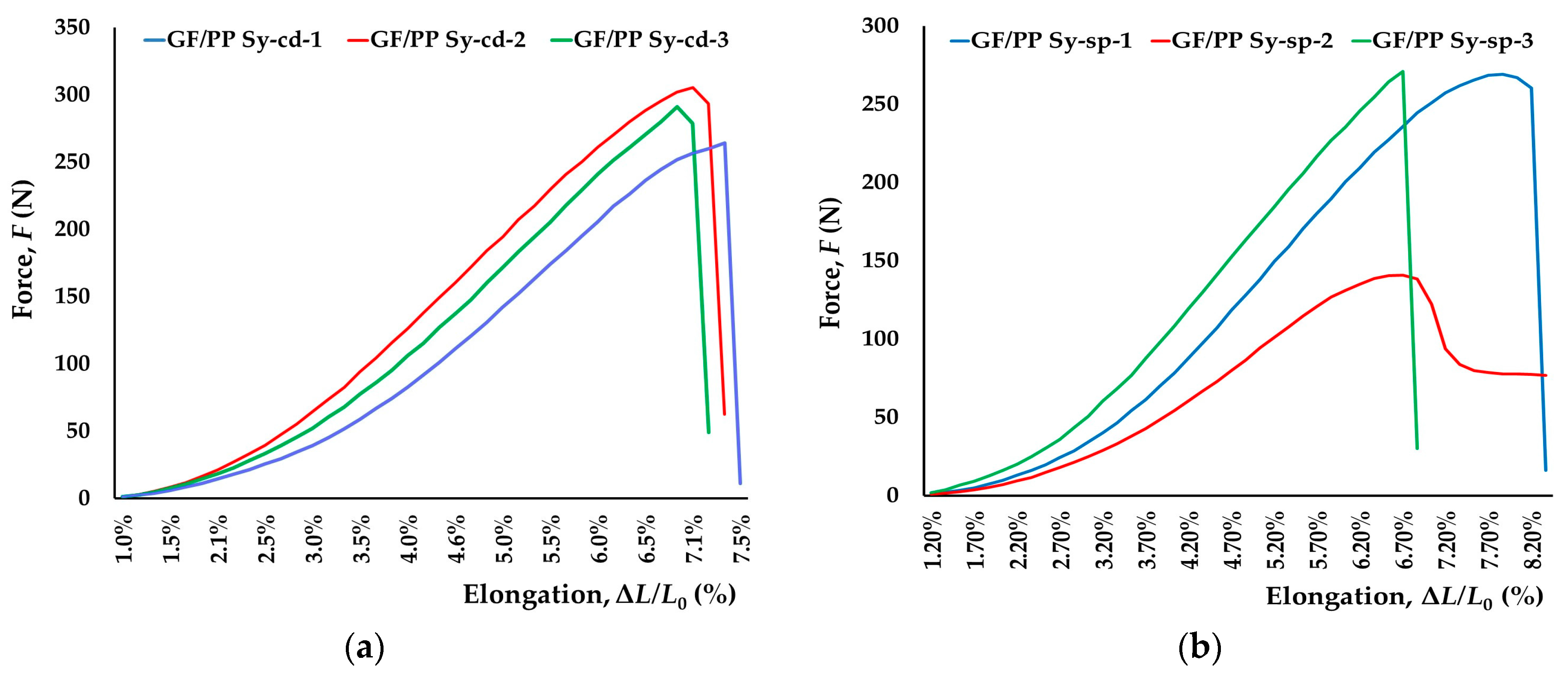
| GF/PP Sy-cd-1 | 930 | 2560 | 264.24 | 7.40 | 3.4738 |
| GF/PP Sy-cd-2 | 950 | 2450 | 305.15 | 6.10 | 4.7615 |
| GF/PP Sy-cd-3 | 920 | 2510 | 290.79 | 6.20 | 3.5767 |
| Average | 933 | 2507 | 286.73 | 6.57 | 3.9373 |
| Standard deviation | 15 | 55 | 20.76 | 0.72 | 0.7156 |
| GF/PP Sy-sp-1 | 880 | 980 | 269.03 | 7.90 | 2.5027 |
| GF/PP Sy-sp-2 | 700 | 800 | 140.80 | 7.20 | 2.0564 |
| GF/PP Sy-sp-3 | 1540 | 1460 | 270.79 | 5.70 | 3.8872 |
| Average | 1040 | 1080 | 226.87 | 6.93 | 2.8154 |
| Standard deviation | 442 | 341 | 74.55 | 1.12 | 0.9546 |
| GF Sy-sp-1 | 1240 | 1200 | 337.69 | 4.50 | 3.9768 |
| GF Sy-sp-2 | 500 | 500 | 490.60 | 6.40 | 3.2110 |
| Average | 870 | 850 | 414.14 | 5.45 | 3.5939 |
| Standard deviation | 523 | 495 | 108.13 | 1.34 | 0.5415 |
| GF/PA66 Sy-sp-1 | 990 | 1150 | 295.41 | 7.30 | 1.1434 |
| GF/PA66 Sy-sp-2 | 810 | 930 | 271.85 | 8.00 | 1.4136 |
| GF/PA66 Sy-sp-3 | 690 | 820 | 214.93 | 6.30 | 1.4665 |
| Average | 830 | 967 | 260.73 | 7.20 | 1.3412 |
| Standard deviation | 151 | 168 | 41.38 | 0.85 | 0.1733 |
© 2017 by the authors. Licensee MDPI, Basel, Switzerland. This article is an open access article distributed under the terms and conditions of the Creative Commons Attribution (CC BY) license (http://creativecommons.org/licenses/by/4.0/).
Share and Cite
Jerkovic, I.; Koncar, V.; Grancaric, A.M. New Textile Sensors for In Situ Structural Health Monitoring of Textile Reinforced Thermoplastic Composites Based on the Conductive Poly(3,4-ethylenedioxythiophene)-poly(styrenesulfonate) Polymer Complex. Sensors 2017, 17, 2297. https://doi.org/10.3390/s17102297
Jerkovic I, Koncar V, Grancaric AM. New Textile Sensors for In Situ Structural Health Monitoring of Textile Reinforced Thermoplastic Composites Based on the Conductive Poly(3,4-ethylenedioxythiophene)-poly(styrenesulfonate) Polymer Complex. Sensors. 2017; 17(10):2297. https://doi.org/10.3390/s17102297
Chicago/Turabian StyleJerkovic, Ivona, Vladan Koncar, and Ana Marija Grancaric. 2017. "New Textile Sensors for In Situ Structural Health Monitoring of Textile Reinforced Thermoplastic Composites Based on the Conductive Poly(3,4-ethylenedioxythiophene)-poly(styrenesulfonate) Polymer Complex" Sensors 17, no. 10: 2297. https://doi.org/10.3390/s17102297
APA StyleJerkovic, I., Koncar, V., & Grancaric, A. M. (2017). New Textile Sensors for In Situ Structural Health Monitoring of Textile Reinforced Thermoplastic Composites Based on the Conductive Poly(3,4-ethylenedioxythiophene)-poly(styrenesulfonate) Polymer Complex. Sensors, 17(10), 2297. https://doi.org/10.3390/s17102297