
Effect of Sensors on the Reliability and Control Performance of Power Circuits in the Web of Things (WoT)

Abstract
:1. Introduction
2. Review of Related Works
3. Reliability of Sensors and Systems
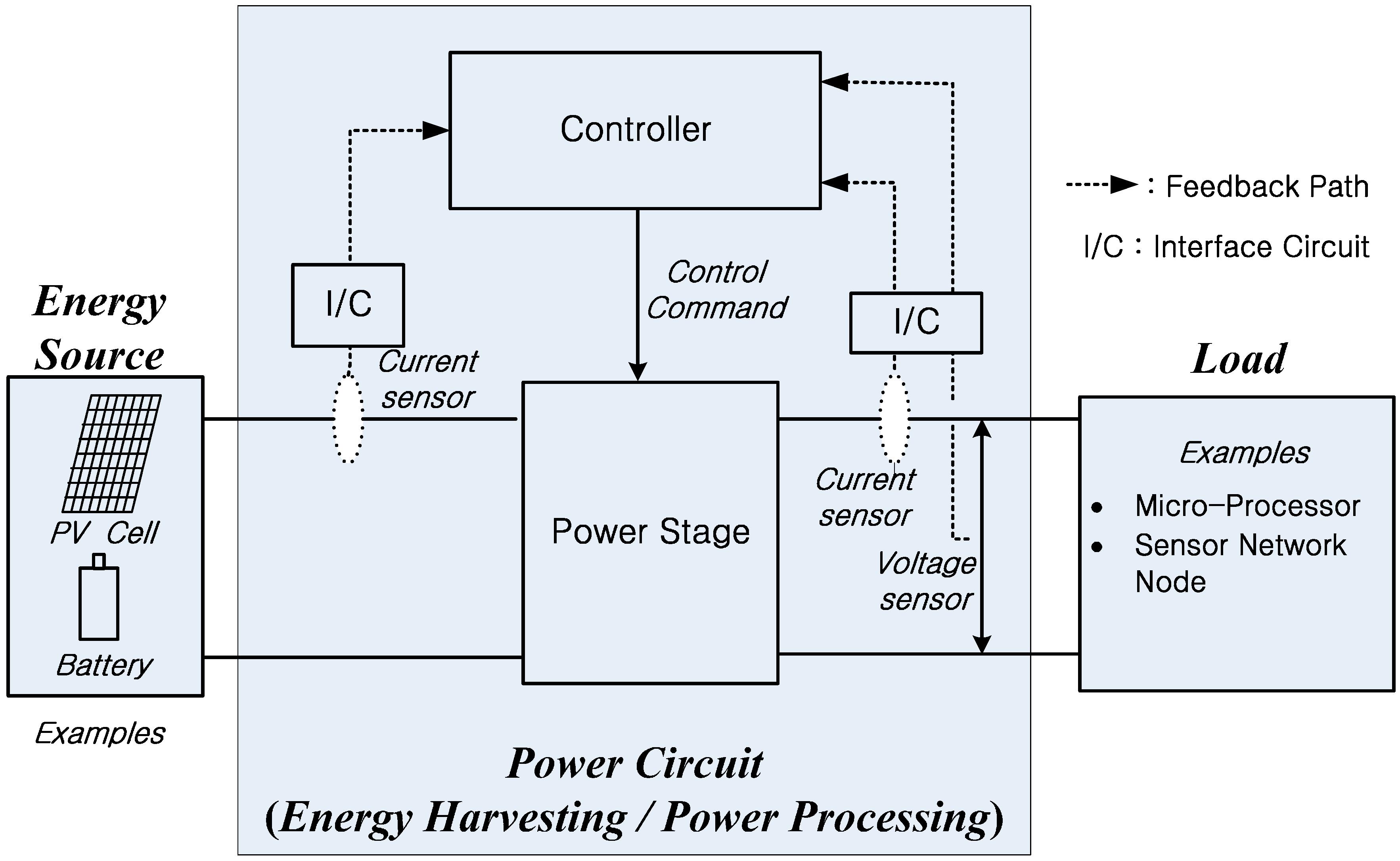
3.1. Control and Reliability of Power Circuits
3.2. Reliability Analysis Considering Sensors
3.3. Further Considerations
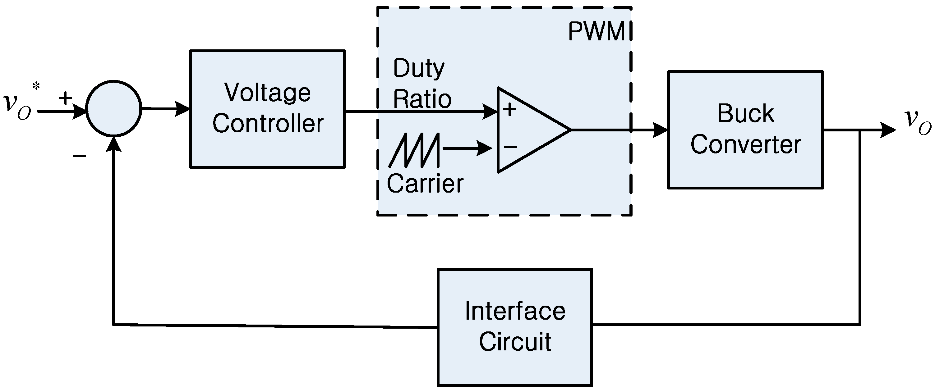
4. Dynamics of the Sensor Interface Circuit and System
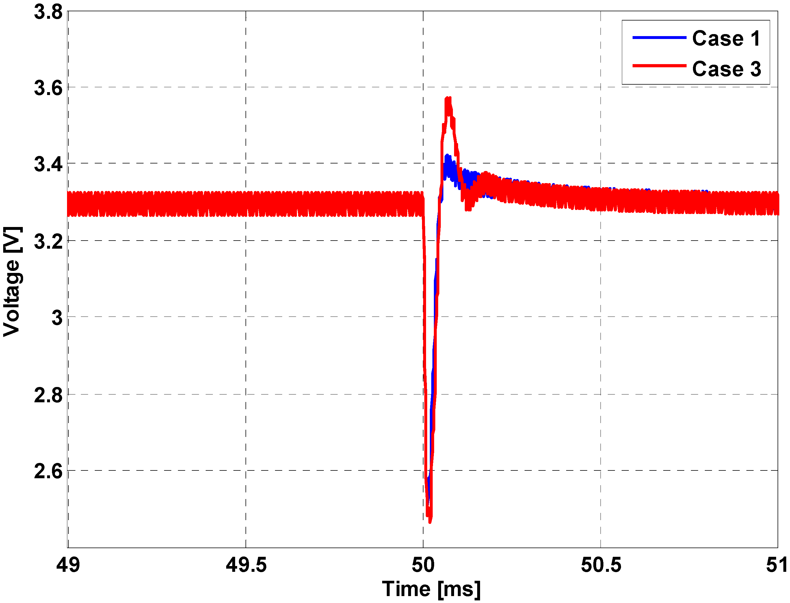
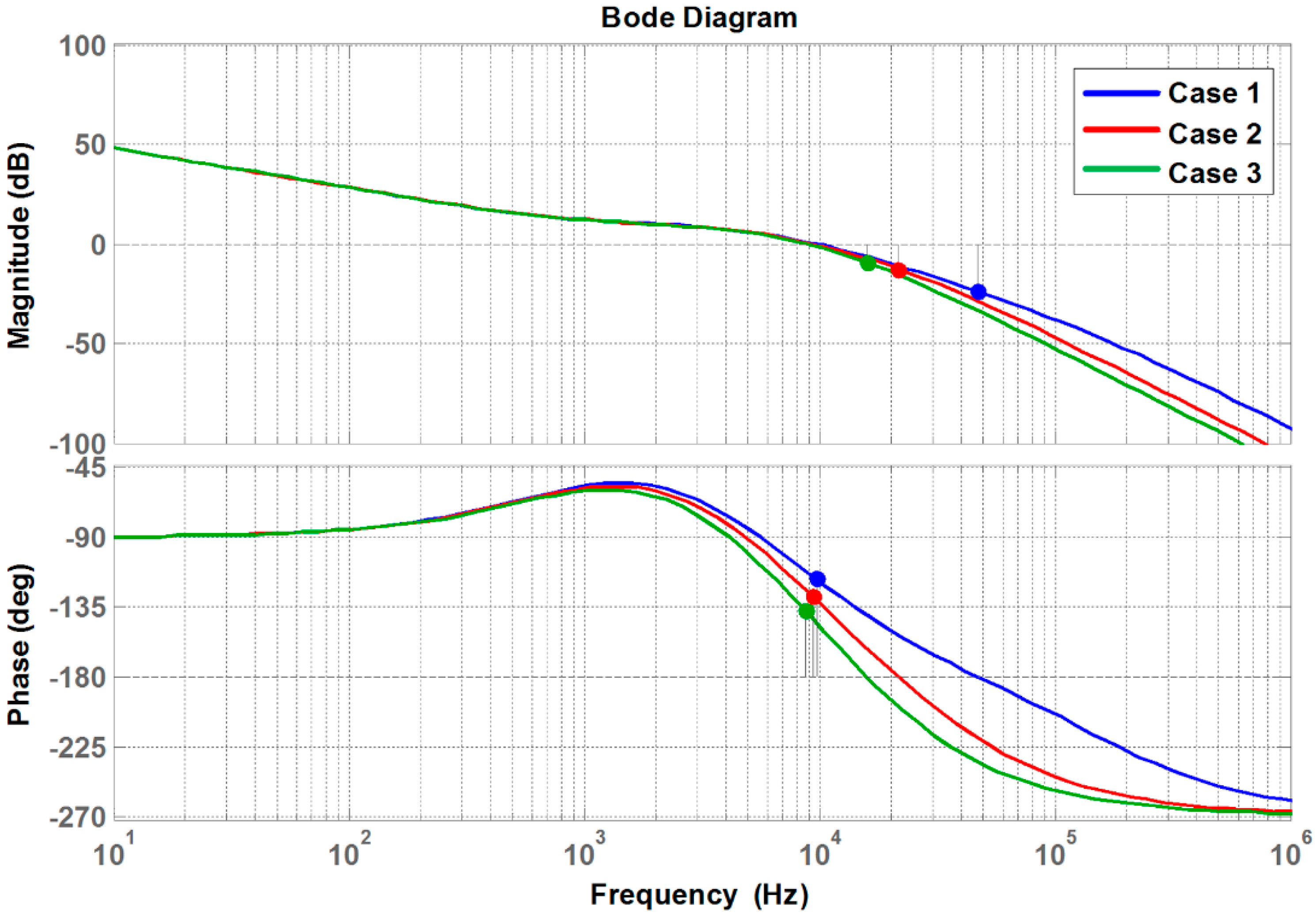
5. Results Analysis
6. Conclusions
Acknowledgments
Author Contributions
Conflicts of Interest
References
- Zou, T.; Lin, S.; Feng, Q.; Chen, Y. Energy-Efficient Control with Harvesting Predictions for Solar-Powered Wireless Sensor Networks. Sensors 2016, 16, 53. [Google Scholar] [CrossRef] [PubMed]
- Hwang, Y.-S.; Chen, J.-J.; Lai, B.-H.; Ku, Y.-T.; Yu, C.-C. A Fast-Transient Boost Converter with Noise-Reduction Techniques for Wireless Sensor Networks. IEEE Sens. J. 2016, 16, 3188–3197. [Google Scholar] [CrossRef]
- Martinez, B.; Montón, M.; Vilajosana, I.; Prades, J.D. The Power of Models: Modeling Power Consumption for IoT Devices. IEEE Sens. J. 2015, 15, 5777–5789. [Google Scholar] [CrossRef]
- Gubbi, J.; Buyya, R.; Marusic, S.; Palaniswami, M. Internet of Things (IoT): A vision, architectural elements, and future directions. Future Gener. Comput. Syst. 2013, 29, 1645–1660. [Google Scholar] [CrossRef]
- Ahn, J.-H.; Kim, D.-H.; Lee, B.-K.; Jin, H.-C.; Shim, J.-S. DC Appliance Safety Standards Guideline through Comparative Analysis of AC and DC Supplied Home Appliances. J. Electr. Eng. Technol. 2012, 7, 51–57. [Google Scholar] [CrossRef]
- Ahmad, M. Reliability Models for the Internet of Things: A Paradigm Shift. In Proceedings of the 2014 IEEE International Symposium on Software Reliability Engineering Workshops (ISSREW), Naples, Italy, 3–6 November 2014; pp. 52–59.
- Jafer, I.; Stack, P.; MacNamee, K. Design of New Power Management Circuit for Light Energy Harvesting System. Sensors 2016, 16, 270. [Google Scholar] [CrossRef] [PubMed]
- Brunelli, D. A High-Efficiency Wind Energy Harvester for Autonomous Embedded Systems. Sensors 2016, 16, 327. [Google Scholar] [CrossRef] [PubMed]
- Burgos, R.; Chen, G.; Wang, F.; Boroyevich, D.; Odendaal, W.G.; Van Wyk, J.D. Reliability-Oriented Design of Three-Phase Power Converters for Aircraft Applications. IEEE Trans. Aerosp. Electron. Syst. 2012, 48, 1249–1263. [Google Scholar] [CrossRef]
- Yu, X.; Khambadkone, A.M. Reliability Analysis and Cost Optimization of Parallel-Inverter System. IEEE Trans. Ind. Electron. 2012, 59, 3881–3889. [Google Scholar] [CrossRef]
- Kolar, J.; Krismer, F.; Lobsiger, Y.; Muhlethaler, J.; Nussbaumer, T.; Minibock, J. Extreme Efficiency Power Electronics. In Proceedings of the 2012 International Conference on Integrated Power Electronics Systems (CIPS), Nuremberg, Germany, 6–8 March 2012; pp. 1–22.
- Bazzi, A.M.; Dominguez-Garcia, A.; Krein, P.T. Markov Reliability Modeling for Induction Motor Drives under Field-Oriented Control. IEEE Trans. Power Electron. 2012, 27, 534–546. [Google Scholar] [CrossRef]
- Fang, C.-C.; Redl, R. Subharmonic Stability Limits for the Buck Converter with Ripple-Based Constant on-Time Control and Feedback Filter. IEEE Trans. Power Electron. 2014, 29, 2135–2142. [Google Scholar] [CrossRef]
- Julian, A.L.; Oriti, G. A Comparison of Redundant Inverter Topologies to Improve Voltage Source Inverter Reliability. IEEE Trans. Ind. Appl. 2007, 43, 1371–1378. [Google Scholar] [CrossRef]
- Tong, Q.; Chen, C.; Zhang, Q.; Zou, X. A Sensorless Predictive Current Controlled Boost Converter by using and EKF with Load Variation Effect Elimination Function. Sensors 2015, 15, 9986–10003. [Google Scholar] [CrossRef] [PubMed]
- Midya, P.; Krein, P.T.; Greuel, M.F. Sensorless Current Mode Control-An Observer-Based Technique for DC-DC Converters. IEEE Trans. Power Electron. 2001, 16, 522–526. [Google Scholar] [CrossRef]
- Kimball, J.W.; Krein, P.T.; Chen, Y. Hysteresis and Delta Modulation Control of Converters using Sensorless Current Mode. IEEE Trans. Power Electron. 2006, 21, 1154–1158. [Google Scholar] [CrossRef]
- Lopez, V.M.; Azcondo, F.J.; de Castro, A.; Zane, R. Universal Digital Controller for Boost CCM Power Factor Correction Stages Based on Current Rebuilding Concept. IEEE Trans. Power Electron. 2014, 29, 3818–3829. [Google Scholar] [CrossRef]
- Kim, H.; Falahi, M.; Jahns, T.M.; Degner, M.W. Inductor Current Measurement and Regulation Using a Single DC Link Current Sensor for Interleaved DC-DC Converters. IEEE Trans. Power Electron. 2011, 26, 1503–1510. [Google Scholar] [CrossRef]
- Li, Y.; Yu, H.; Su, B.; Shang, Y. Hybrid Micropower Source for Wireless Sensor Network. IEEE Sens. J. 2008, 8, 678–681. [Google Scholar] [CrossRef]
- Abdi, B.; Ranjbar, A.H.; Gharehpetian, G.B.; Milimonfared, J. Reliability Considerations for Parallel Performance of Semiconductor Switches in High-Power Switching Power Supplies. IEEE Trans. Ind. Electron. 2009, 56, 2133–2139. [Google Scholar] [CrossRef]
- Chan, F.; Calleja, H. Reliability Estimation of Three Single-Phase Topologies in Grid-Connected PV Systems. IEEE Trans. Ind. Electron. 2011, 58, 2683–2689. [Google Scholar] [CrossRef]
- Smater, S.S.; Dominguez-Garcia, A.D. A Framework for Reliability and Performance Assessment of Wind Energy Conversion Systems. IEEE Trans. Power Syst. 2011, 26, 2235–2245. [Google Scholar] [CrossRef]
- Dhople, S.V.; Davoudi, A.; Domínguez-García, A.D.; Chapman, P.L. A Unified Approach to Reliability Assessment of Multiphase DC–DC Converters in Photovoltaic Energy Conversion Systems. IEEE Trans. Power Electron. 2012, 27, 739–751. [Google Scholar] [CrossRef]
- Julian, A.L.; Oriti, G.; Blevins, S.T. Operating Standby Redundant Controller to Improve Voltage-Source Inverter Reliability. IEEE Trans. Ind. Appl. 2010, 46, 2008–2014. [Google Scholar] [CrossRef]
- Geyer, T.; Schroder, S. Reliability Considerations and Fault-Handling Strategies for Multi-MW Modular Drive systems. IEEE Trans. Ind. Appl. 2010, 46, 2442–2451. [Google Scholar] [CrossRef]
- Jiang, W.; Fahimi, B. Current Reconstruction Techniques for Survivable Three-Phase PWM Converters. IEEE Trans. Power Electron. 2010, 25, 188–192. [Google Scholar] [CrossRef]
- Aroudi, A.E.; Calvente, J.; Giral, R.; Al-Numay, M.; Martinez-Salamero, L. Boundaries of Subharmonic Oscillations Associated to Filtering Effects of Controllers and Current Sensors in Switched Converters Under CMC. IEEE Trans. Ind. Electron. 2016, 63, 4826–4837. [Google Scholar] [CrossRef]
- Chen, J.-J.; Hwang, Y.-S.; Yu, J.-H.; Ku, Y.-T.; Yu, C.-C. A Low-EMI Buck Converter Suitable for Wireless Sensor Networks with Spur-Reduction Techniques. IEEE Sens. J. 2016, 16, 2588–2597. [Google Scholar] [CrossRef]
- Krug, M.; Hartmann, J.; Gröll, L.; Gengenbach, U.; Nagel, J.; Bretthauer, G. Model-Based Dual-Mode Controller for Low-Power Buck Converters. In Proceedings of the 2014 International Conference on Optimization of Electrical and Electronic Equipment (OPTIM), Bran, Romania, 22–24 May 2014; pp. 489–497.
- Krein, P.T. Elements of Power Electronics; Oxford University Press: New York, NY, USA, 1998. [Google Scholar]
- Hartmann, L.V.; Corrêa, M.B.; Lima, A.M. A Simple and Effective Control Strategy for Improved Operation of a Current-Fed Push-Pull Converter. In Proceedings of the 2010 IEEE Energy Conversion Congress and Exposition, Atlanta, GA, USA, 12–16 September 2010; pp. 1098–1103.
- Tsang, K.; Chan, W. Cascade Controller for DC/DC Buck Convertor. IEE Proc. Electr. Power Appl. 2005, 152, 827–831. [Google Scholar] [CrossRef]
- Dallago, E.; Passoni, M.; Sassone, G. Lossless Current Sensing in Low-Voltage High-Current DC/DC Modular Supplies. IEEE Trans. Ind. Electron. 2000, 47, 1249–1252. [Google Scholar]
- Pajer, R.; Milanoviĉ, M.; Premzel, B.; Rodiĉ, M. MOS-FET as a Current Sensor in Power Electronics Converters. Sensors 2015, 15, 18061–18079. [Google Scholar] [CrossRef] [PubMed]
- Patel, A.; Ferdowsi, M. Current Sensing for Automotive Electronics—A Survey. IEEE Trans. Veh. Technol. 2009, 58, 4108–4119. [Google Scholar] [CrossRef]
- LF 2005-S/SP13 User Guide, LEM SA. Available online: http://www.lem.com/docs/manuals/LF%202005-S%20SP13_en.pdf (accessed on 10 August 2016).
- Kapat, S.; Krein, P.T. Formulation of PID control for DC–DC converters based on capacitor current: A geometric context. IEEE Trans. Power Electron. 2012, 27, 1424–1432. [Google Scholar] [CrossRef]
- Lukic, Z.; Zhao, Z.; Ahsanuzzaman, S.; Prodic, A. Self-Tuning Digital Current Estimator for Low-Power Switching Converters. In Proceedings of the 2008 IEEE Applied Power Electronics Conference and Exposition (APEC), Austin, TX, USA, 24–28 February 2008; pp. 529–534.
- Mezger, F.; Killat, D. A Digital Observer based Current Loop Control for Buck Converters. In Proceedings of the 2013 Conference of the IEEE Industrial Electronics Society (IECON), Vienna, Austria, 10–13 November 2013; pp. 181–186.
- Castelló, J.; Espí, J.M.; García-Gil, R. A New Generalized Robust Predictive Current Control for Grid-Connected Inverters Compensates Anti-Aliasing Filters Delay. IEEE Trans. Ind. Electron. 2016, 63, 4485–4494. [Google Scholar] [CrossRef]
- Ellis, G. Control System Design Guide: A Practical Guide, 3rd ed.; Elsevier Academic Press: San Diego, CA, USA, 2004. [Google Scholar]
- Erickson, R.W.; Maksimovic, D. Fundamentals of Power Electronics, 2nd ed.; Kluwer Academic Publishers: Norwell, MA, USA, 2001. [Google Scholar]
- Chang, Y.-T.; Lai, Y.-S. Effect of Sampling Frequency of A/D Converter on Controller Stability and Bandwidth of Digital-Controlled Power Converter. In Proceedings of the 2007 International Conference on Power Electronics (ICPE), Daegu, Korea, 22–26 October 2007; pp. 625–629.


| Case Number | Inductor Current | Capacitor Current | Load Current |
|---|---|---|---|
| 1 | O | O | O |
| 2 | O | X | O |
| 3 | O | O | X |
| 4 | O | X | X |
| 5 | X | O | O |
| 6 | X | X | O |
| 7 | X | O | X |
| 8 | X | X | X |
| System Parameter | Value |
|---|---|
| Inductance | 25 μH |
| Capacitance | 22 μF |
| Source Voltage | 16 V |
| Voltage Controller | Kp = 0.2, Ki = 1000 |
| Switching Frequency | 100 kHz |
| Case Number | Interface Circuit Time Constant | PM |
|---|---|---|
| Case 1 | 1 μs | 63.1° |
| Case 2 | 5 μs | 51.7° |
| Case 3 | 10 μs | 42.7° |
| System Parameter | Value |
|---|---|
| Inductanace | 1 mH |
| Capacitance | 125 μF |
| Source Voltage | 50 V |
| Voltage Controller | Kp = 0.1, Ki = 83.33 |
| Current Controller | Kp = 0.666, Ki = 5555 |
| Switching Frequency | 100 kHz |
© 2016 by the authors; licensee MDPI, Basel, Switzerland. This article is an open access article distributed under the terms and conditions of the Creative Commons Attribution (CC-BY) license (http://creativecommons.org/licenses/by/4.0/).
Share and Cite
Bae, S.; Kim, M. Effect of Sensors on the Reliability and Control Performance of Power Circuits in the Web of Things (WoT). Sensors 2016, 16, 1430. https://doi.org/10.3390/s16091430
Bae S, Kim M. Effect of Sensors on the Reliability and Control Performance of Power Circuits in the Web of Things (WoT). Sensors. 2016; 16(9):1430. https://doi.org/10.3390/s16091430
Chicago/Turabian StyleBae, Sungwoo, and Myungchin Kim. 2016. "Effect of Sensors on the Reliability and Control Performance of Power Circuits in the Web of Things (WoT)" Sensors 16, no. 9: 1430. https://doi.org/10.3390/s16091430
APA StyleBae, S., & Kim, M. (2016). Effect of Sensors on the Reliability and Control Performance of Power Circuits in the Web of Things (WoT). Sensors, 16(9), 1430. https://doi.org/10.3390/s16091430