1. Introduction
Optical fiber refractometers are of great importance to the biochemical sensing field due to the advantages of high sensitivity, compact size, and anti-electromagnetic interference. For most of the fiber-based refractometers, the response of the sensor to changes in surrounding refractive index (SRI) is nonlinear, in which the sensitivity is much higher for an SRI close to 1.45 (which is the fiber material refractive index), but lower for an SRI close to 1.33 [
1,
2]. In order to improve SRI sensitivity in the vicinity of an SRI of 1.33 (which is the environment refractive index of the most of biosensors), nanofilm-coated optical fibers with metallic materials, semiconductor materials or high refractive index dielectric materials have been widely investigated [
3,
4,
5,
6,
7,
8,
9,
10,
11,
12,
13]. One strategy is the deposition of high refractive index nanofilm on fibers which exhibit a mode resonant feature. These fibers include long period gratings (LPGs) fiber [
3,
4,
5], double cladding fiber (DCF) [
6], and cascading single-mode–multi-mode–single-mode (SMS) fiber [
7]. It has been demonstrated that the sensitivity of these SRI sensors can be enhanced by mode reorganization behavior. However, since the SRI sensitivity can only be improved significantly in the transition region, the enhancement is limited. Hence, the schemes based on fibers without mode resonant feature are developed, including adiabatic tapered optical fiber, D-shaped optical fiber, cladding-removed multimode optical fiber, etc. Depending on the properties of the nanofilm, these fiber-optic refractometers without mode resonance work based on either surface Plasmon resonance (SPR) [
8,
9] or lossy modes resonance (LMR) [
10,
11,
12,
13]. For SPR-based refractometers, the real part of the permittivity of the coated nanofilm is negative and higher in magnitude than both its own imaginary part and the permittivity of the material surrounding the nanofilm. In this case, the evanescent wave in the fiber is coupled to the surface Plasmon polariton. For LMR-based refractometers, the fiber is coated by high refractive index-absorbing nanofilm, whose real part of permittivity is positive and higher in magnitude than both its own imaginary part and the permittivity of the material surrounding the nanofilm, such as indium tin oxide (ITO) [
10,
11], titanium dioxide (TiO
2) [
12], aluminum oxide (Al
2O
3) [
13], and [PAH-PAA]
X polymeric thin film [
14]. Light guided in these structures is coupled to the lossy mode in the nanofilm. LMR has the advantage that it can be generated using a wide variety of materials in a wide spectral range.
The common technologies used to deposit nanofilms on optical fiber include dip-coating method [
15], self-assembly method [
12,
14], sputtering technique [
10,
11], etc. However, precise control of film thickness cannot be achieved by dip-coating method. Self-assembly method requires the precise control of external parameters (pressure, humidity, temperature, etc.) to produce homogeneous and repetitive nanofilm. For sputtering technique, it is difficult to form a uniform nanofilm around the fiber’s cylindrical surface. Recently, atomic layer deposition (ALD) technology is considered to be one of the most promising nanofilm deposition techniques in optical fiber fields [
16]. ALD technology is a conformal deposition process through sequential, self-limiting surface reactions. Compared with conventional fiber coating technologies, ALD technology has special advantages, including accurate thickness control, good conformity for complex shapes, excellent step coverage, and good uniformity and adhesion. Many studies have shown that ALD is very suitable for coating a nanofilm on the rod shape of an optical fiber to realize functional fiber components [
13,
17,
18,
19].
Adiabatic tapered optical fiber sensors have been studied in previous work by coating Al
2O
3 via ALD technology. It was demonstrated that SRI sensitivity can be improved by coating with nanofilms with higher refractive indices [
13]. TiO
2 has a higher refractive index than Al
2O
3, with advantages such as lack of toxicity and good biocompatibility, making it more suitable for biochemical sensing. In this paper, we have experimentally demonstrated that TiO
2 can be coated on tapered optical fiber by using ALD technology for high sensitivity refractometers. Theoretical analysis is also conducted based on ray optics to explain the interference resonance inside the fiber. The optical field confined in the tapered fiber leaks out into the nanofilm, and multiple beam interference occurs, which can be regarded as a thin film Fabry–Perot (F-P) resonator. Its resonant transmission spectrum depends strongly on the SRI variation, which allows the detection of SRI with high sensitivity. The refractometer developed by depositing 50.9-nm-thickness TiO
2 on the tapered fiber shows an SRI sensitivity of 7096 nm/RIU in the SRI range of 1.3373–1.3500.
2. Theory
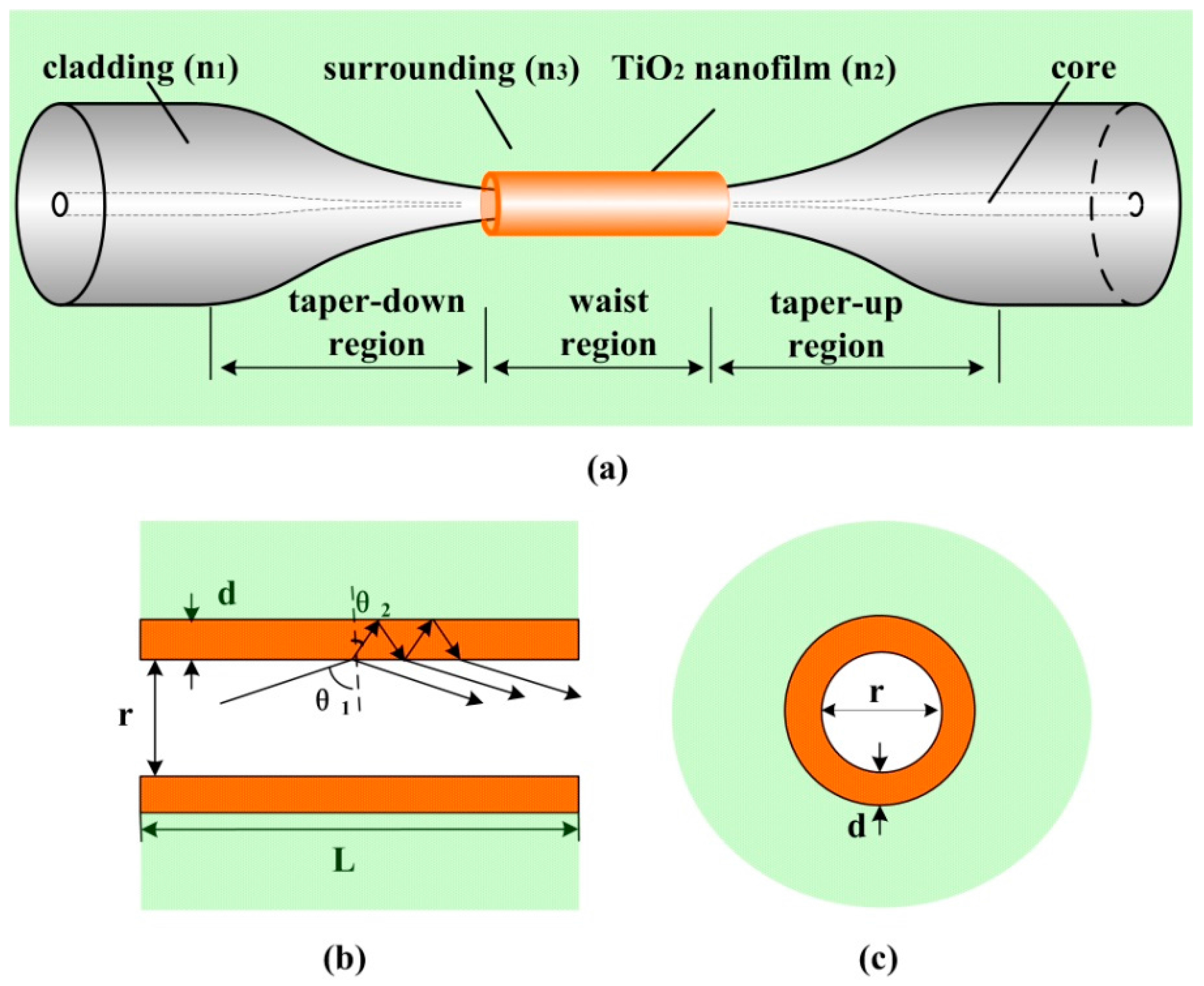
To simulate a sensor based on an adiabatic tapered optical fiber with a high refractive index nanofilm as shown in
Figure 1, a theoretical model was developed, and the applicability of this method has been proven successfully in [
13] for Al
2O
3-coated tapered optical fiber. For the adiabatic tapered fiber with a uniform waist, the transmission loss is almost negligible because of the weak energy of the excited high-order modes, and only fundamental mode is considered to propagate in the taper waist section [
20]. Therefore, the theoretical model of the tapered fiber sensor can be simplified to be a nanofilm-coated cylindrical waveguide with infinite surrounding, where
refers to diameter,
refers to length,
refers to nanofilm thickness,
refers to SRI, as shown in
Figure 1b,c. Since the nanofilm refractive index is higher than that of the fiber taper, light waves cannot be confined in the fiber by total internal reflection (TIR). As depicted in
Figure 1b, when the light strikes on the taper–nanofilm interface with grazing incidence, the light will be partially reflected, and then be completely reflected at the nanofilm–surrounding interface. As a result, multiple beam interference occurs along the tapered fiber, just like a thin film F-P interferometer. The transmission will present a periodic interference spectrum.
If the propagation light wave in the fiber taper is not polarized, the combination of the reflected power in s and p polarization should be taken into account. The light path presents a zigzag ray trajectory due to multiple reflections on the taper-nanofilm interface. The general expression for the transmission is [
21]
and
can be described as [
22]
where
and
are the Fresnel coefficients for s and p polarization of the taper–nanofilm interface, and
and
are the Fresnel coefficients for s and p polarization of the nanofilm–surrounding interface, respectively.
is the phase delay induced by optical path difference,
is the nanofilm refractive index,
is the incidence angle on the nanofilm–surrounding interface. If the nanofilm is lossy, its refractive index becomes a complex one.
is the number of reflections at the taper–nanofilm interface, and
is the incidence angle on the taper–nanofilm interface. For the fundamental mode, can be expressed by
, where
,
is the propagation constant of the fundamental mode, and
is the cladding refractive index.
Since each incident angle corresponds to a fixed wavelength for the fundamental mode, the transmission presents interference dips at different wavelengths, as follows [
23]:
where
is the phase delay induced by the Goos–Hänchen shift due to the TIR on the nanofilm–surrounding interface,
is for s polarization,
is for p polarization, and
. It is obvious that the dips will shift as a function of the nanofilm thickenss, the nanofilm refractive index, and the SRI from Equation (4). When the nanofilm thickenss and refractive index are defined, the SRI sensing can be realized by monitoring the shifts of the dips.
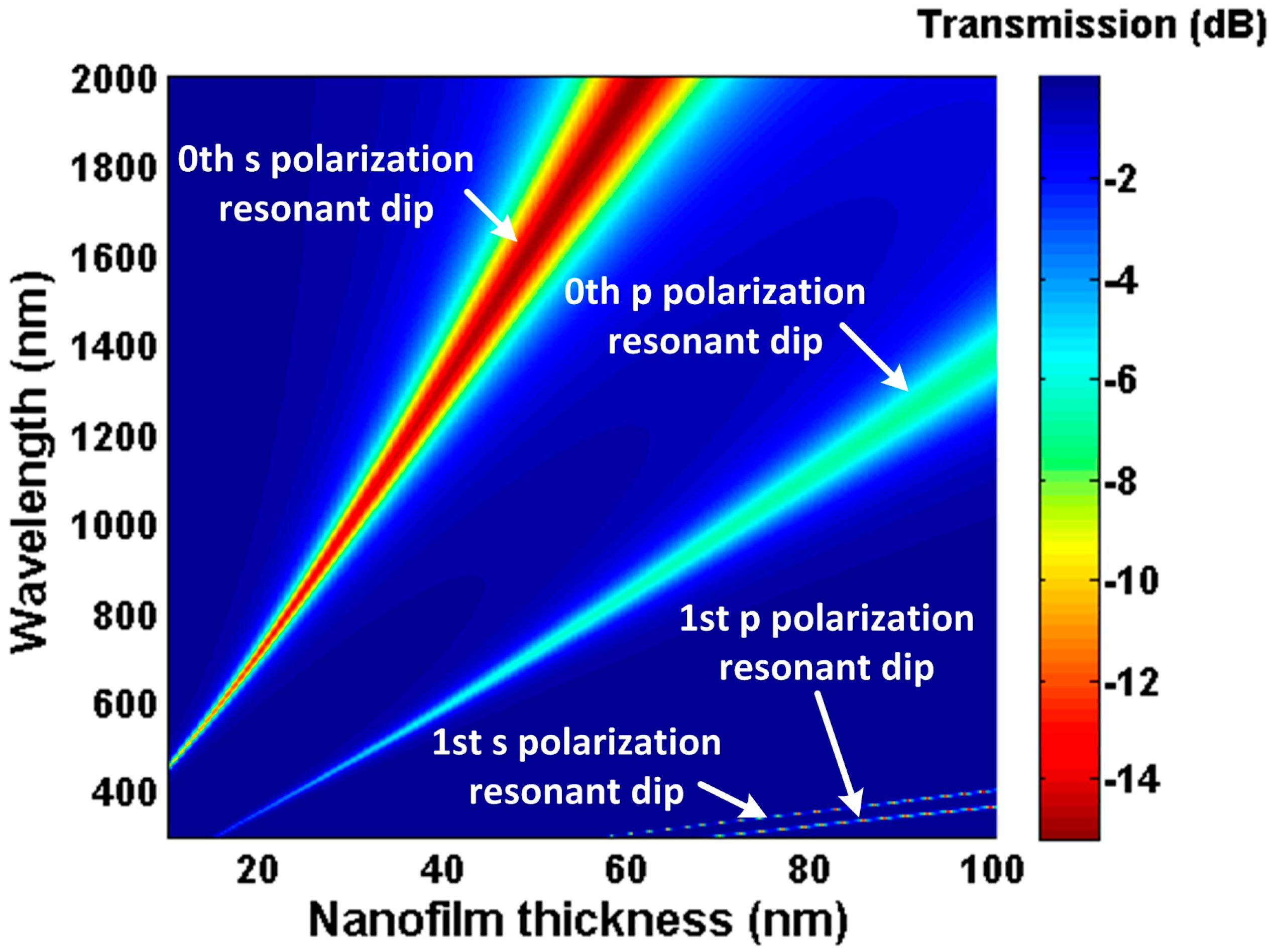
Simulation results using the above model are presented in
Figure 2 and
Figure 3. In the simulation, material dispersion of refractive index for the TiO
2 nanofilm was referred from [
24] (n
TiO2 ≈ 2.278 @ 1550 nm), and the imaginary part was set as 0.005. The waist diameter and length are 25 µm and 7 mm, respectively. In
Figure 2, there are multiple resonant dips generated by the asymmetric F-P resonator. The mth resonant pairs correspond to different polarization transmission, which has been demonstrated in [
13]. These resonant spectra present red shift and bandwidth broadening with the increase of the nanofilm thickness, and the low order resonant spectrum shifts faster than the high order one. Attributed to the spectral dependency of the nanofilm, the resonant wavelength can be tuned from the visible to the near-infrared wavelength band. For a definite nanofilm material, it is possible to tune the resonant dip conveniently by changing the nanofilm thickness.
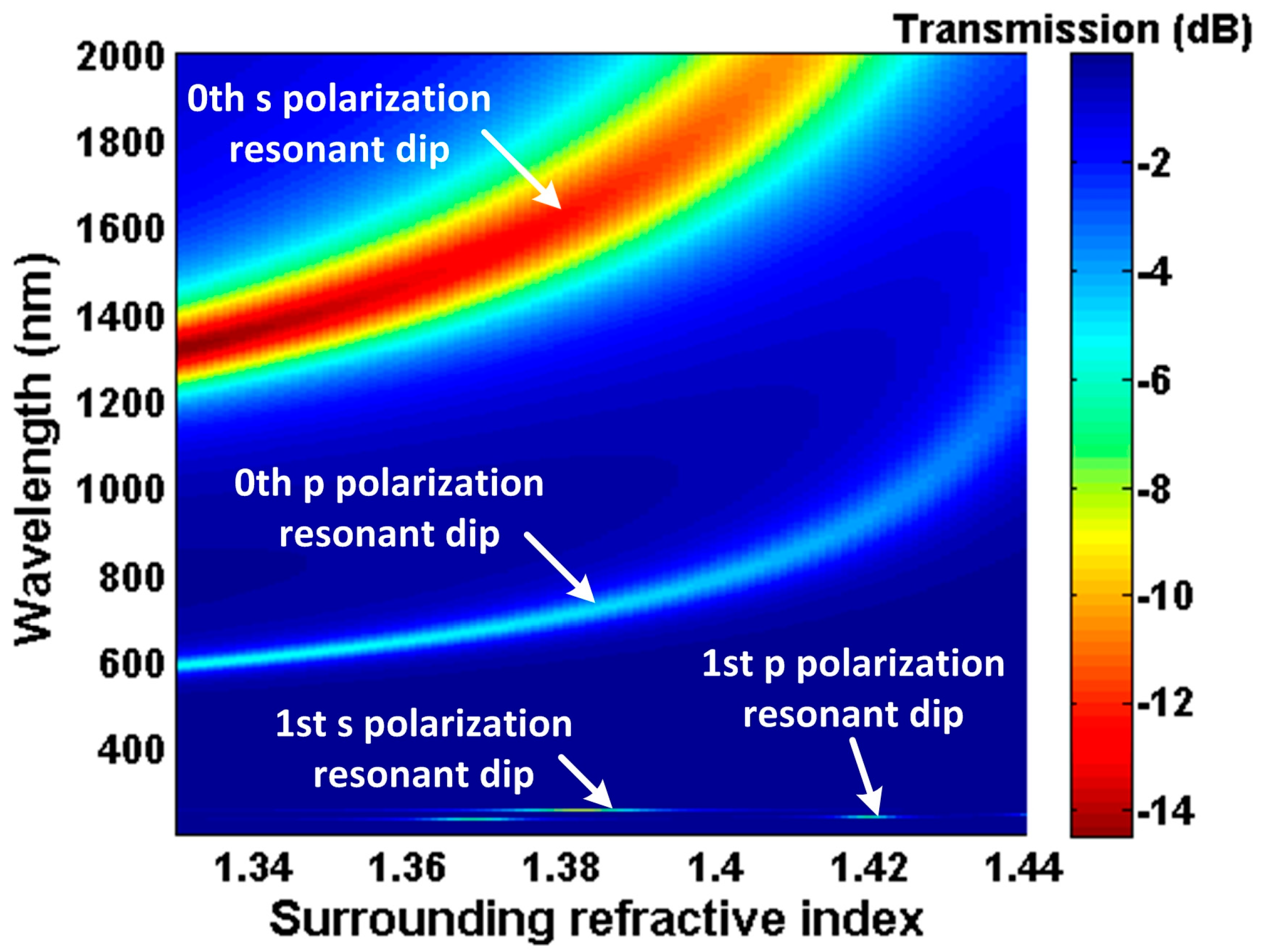
As shown in
Figure 3, we observe that the resonant wavelengths shift to longer wavelength as the SRI increases. According to Equation (4), when the nanofilm refractive index and thickness are defined, the variation of SRI causes
and
of the nanofilm–surrounding interface to change. As a result, the phase delay induced by the Goos–Hänchen shift changes, which leads to the shift of the transmission interference spectrum. Moreover, it can be found that the wavelength shift of the 0th s polarization resonant dip is larger than others; namely, the sensitivity of the 0th s polarization resonant dip is highest [
13]. Hence, we only focus on the 0th s polarization resonant dip in the following work. By monitoring the shift of the 0th s polarization resonant dip, the change of the SRI can be obtained. Additionally, in
Figure 2, the 0th s polarization resonant dip sweeps the range 500 nm–2000 nm between thickness 10 nm and 60 nm. Therefore, the resonant wavelength position (working point) can be controlled by changing the nanofilm thickness.
Meanwhile, temperature stability of the refractometer was studied. The thermo-optic coefficient of the TiO
2 nanofilm, the fiber cladding, and the water is −4.2 ± 0.7 × 10
−5/°C [
24], 7.8 × 10
−6/°C [
25], and −9 × 10
−5/°C [
26], respectively. These refractive indices have slight changes with the temperature fluctuation. According to Equation (4), we can calculate the sensitivity of the 0th resonant dip to temperature (d = 40 nm), which is 0.48 nm/°C for the s polarization resonant dip and 0.18 nm/°C for the p polarization resonant dip. When SRI changes by 0.002 RIU (the SRI step in the experiment), a resonant wavelength shift of 9.0 nm for the s polarization resonant dip and 3.6 nm for the p polarization resonant dip can be achieved. However, a change in temperature of 18.8 °C is required to obtain the same amount of shift. Therefore, a shift in temperature by 1 °C results in a change of the measured refractive index by 1 × 10
−4 RIU.
4. Experiments and Results
With a broadband light source (NKT Photonics SuperK Compact, 500 nm–2400 nm) and two optical spectrum analyzers (AQ-6315A <600 nm–1700 nm>, AQ-6375 <1200 nm–2400 nm>), the transmission spectra of the tapered fiber with TiO
2 film thickness of 39.7 nm, 45.2 nm, and 50.9 nm were measured in air and in deionized water, as shown in
Figure 6a,b, respectively. We observe that the 0th resonant dips shift to the longer wavelength and the bandwidth of the resonant spectra are markedly broadened as the TiO
2 film thickness increases, both in air and in deionized water. Moreover, for the TiO
2 film with the same thickness, the resonant wavelengths exhibit a red shift with switching from air to deionized water, which indicates that the TiO
2-coated adiabatic tapered fiber is sensitive to the change of SRI.
Figure 6c shows that the shift of the resonant wavelength is linearly proportional to the nanofilm thickness. According to this relationship, we can set the deposition cycle to adjust the working point. The experimental results obtained in
Figure 6c show good agreement with the theoretical results.
In the sensing experiment for SRI, the fiber taper sensor head was fixed on a glass microscope slide, and liquid samples with different refractive indices were dropped on the sensor head. A mixture of glycerol and deionized water in different ratios was used as the liquid sample. The SRI is from 1.3373 to 1.3500, which was certified by using an Abbe refractometer with a resolution of 0.0001. The temperature around the sensor head was maintained at approximately 20 °C in order to minimize the SRI/temperature cross sensitivity. In addition, the sensor head was cleaned by deionized water and dried after each sample measurement.
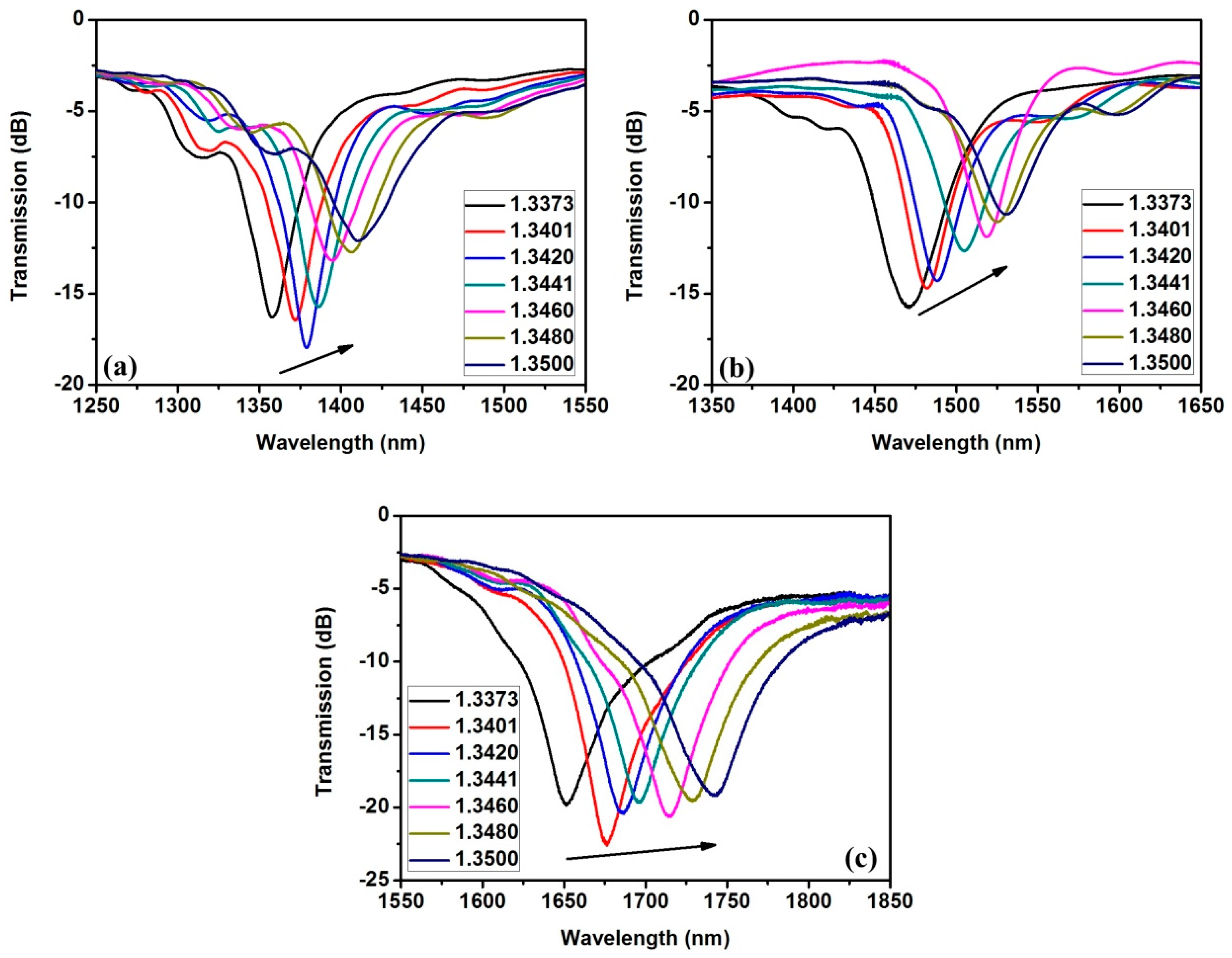
Three sensors with TiO
2 film thickness of 39.7 nm, 45.2 nm, and 50.9 nm were fabricated and investigated. The transmission spectra versus SRI are shown in
Figure 7a–c. As the SRI increases, all of the transmission spectra shift toward the longer wavelength. According to Equation (4), this relationship results from the decrease in the phase delay induced by the Goos–Hänchen shift in the total internal reflection on the nanofilm–surrounding interface. In addition, the shift amount increases gradually with the increase of nanofilm thickness. The reason is that the incident angle for the same order resonant dip will increase to satisfy the phase interference condition, which will lead to an increase in the Goos–Hänchen phase delay change rate according to the TIR feature [
23]. Hence, a greater amount of shift can be obtained with increasing nanofilm thickness. Namely, the shift amount increases as the resonant wavelength shifts to a longer wavelength.
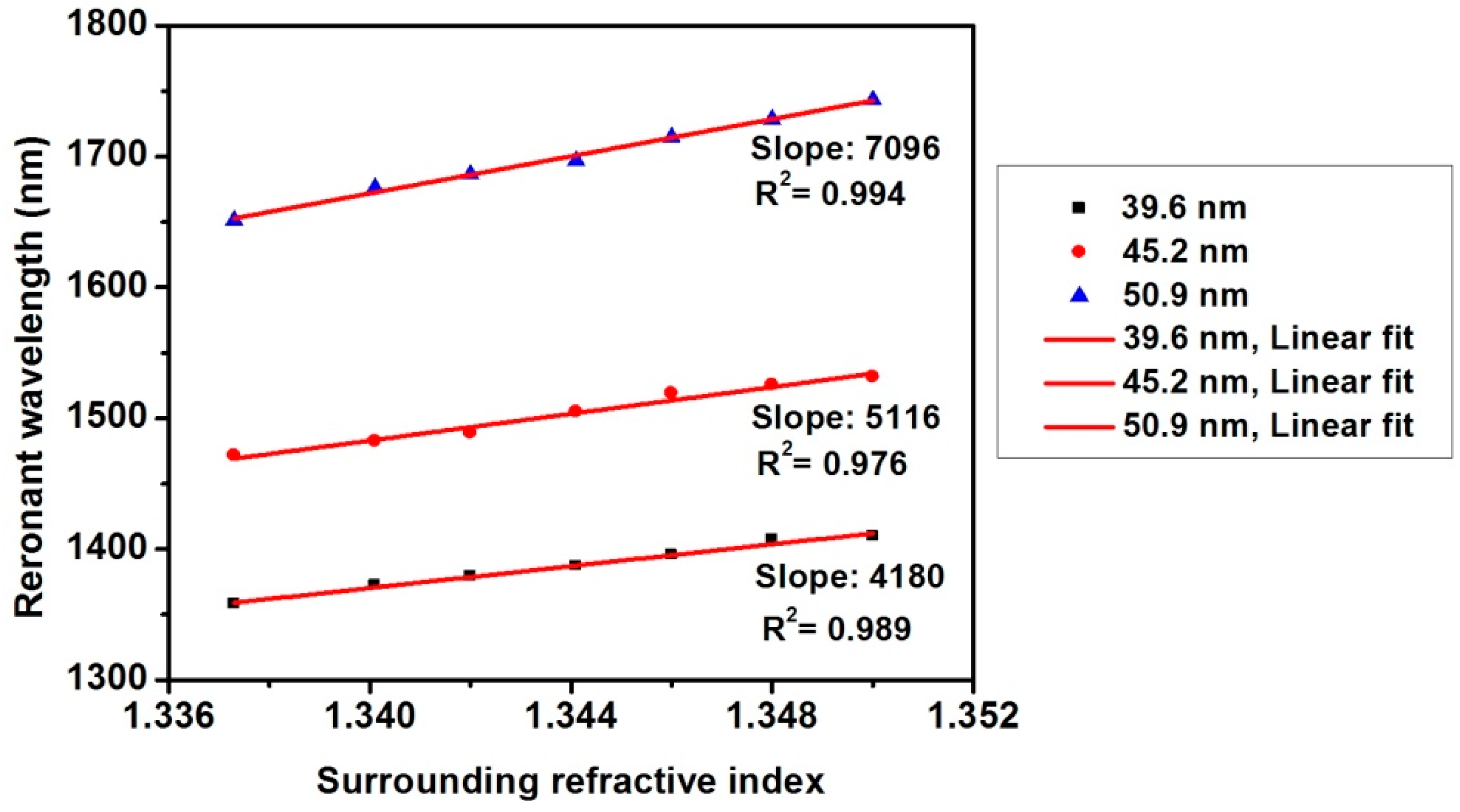
In
Figure 8, we can also observe that the shift of the resonant wavelength is a linear function of the SRI. It shows that the sensitivity is enhanced for the sensor head with thicker nanofilms. The sensitivity of the tapered fiber with TiO
2 film thickness of 39.7 nm, 45.2 nm, and 50.9 nm are 4180 nm/RIU, 5116 nm/RIU, and 7096 nm/RIU, respectively. Moreover, compared with the tapered fiber coated with Al
2O
3 nanofilm where the maximum sensitivity is 6008 nm/RIU [
13], the sensitivity of the tapered fiber coated with TiO
2 nanofilm has been improved, which results from the higher refractive index of TiO
2. These results agree with previous discussion that either increasing nanofilm thickness or increasing nanofilm refractive index can improve the sensitivity for the same order resonant dip.
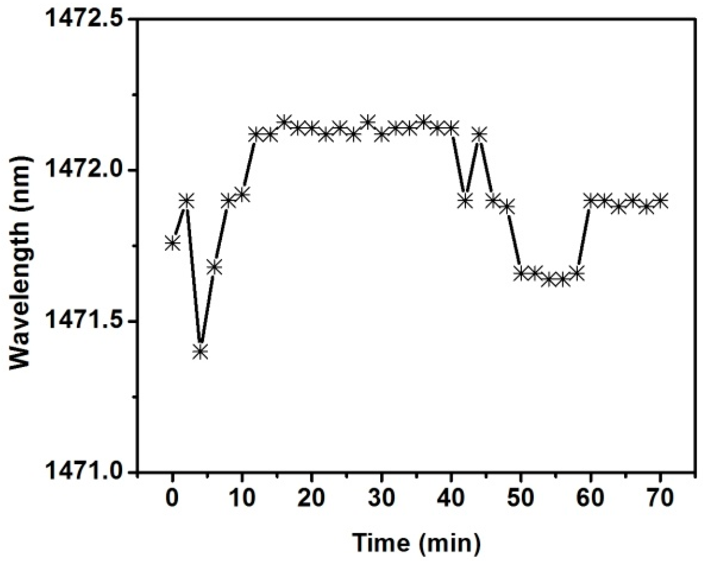
The stability characteristic of the refractometer is also studied. The liquid sample with a refractive index of 1.3369 was dropped on the sensor head with a TiO
2 film thickness of 45.2 nm. The transmission spectrum was acquired every 2 min. In order to minimize the effect of liquid sample evaporation on the experimental results during a 70-min test, the sensor head was sealed in a small plastic box. As shown in
Figure 9, the resonant wavelength fluctuates very little over time, and the Root Mean Square (RMS) value of the fluctuation is about 0.2 nm. The change in refractive index corresponding to the measured wavelength fluctuation is 1.5 × 10
−4. The result indicates that the refractometer has good stability.


