
Two Capacitive Micro-Machined Ultrasonic Transducers for Wind Speed Measurement


Abstract
:1. Introduction
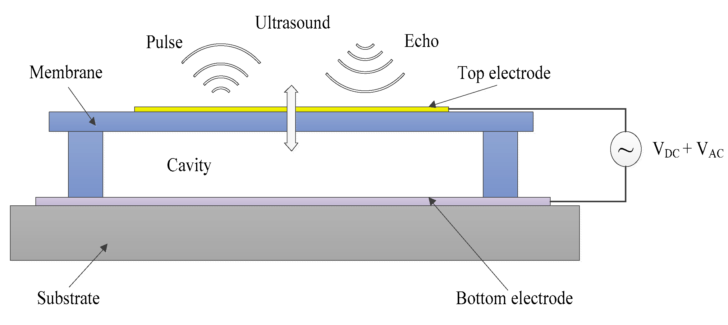
2. CMUT Design
3. Measurement Principle
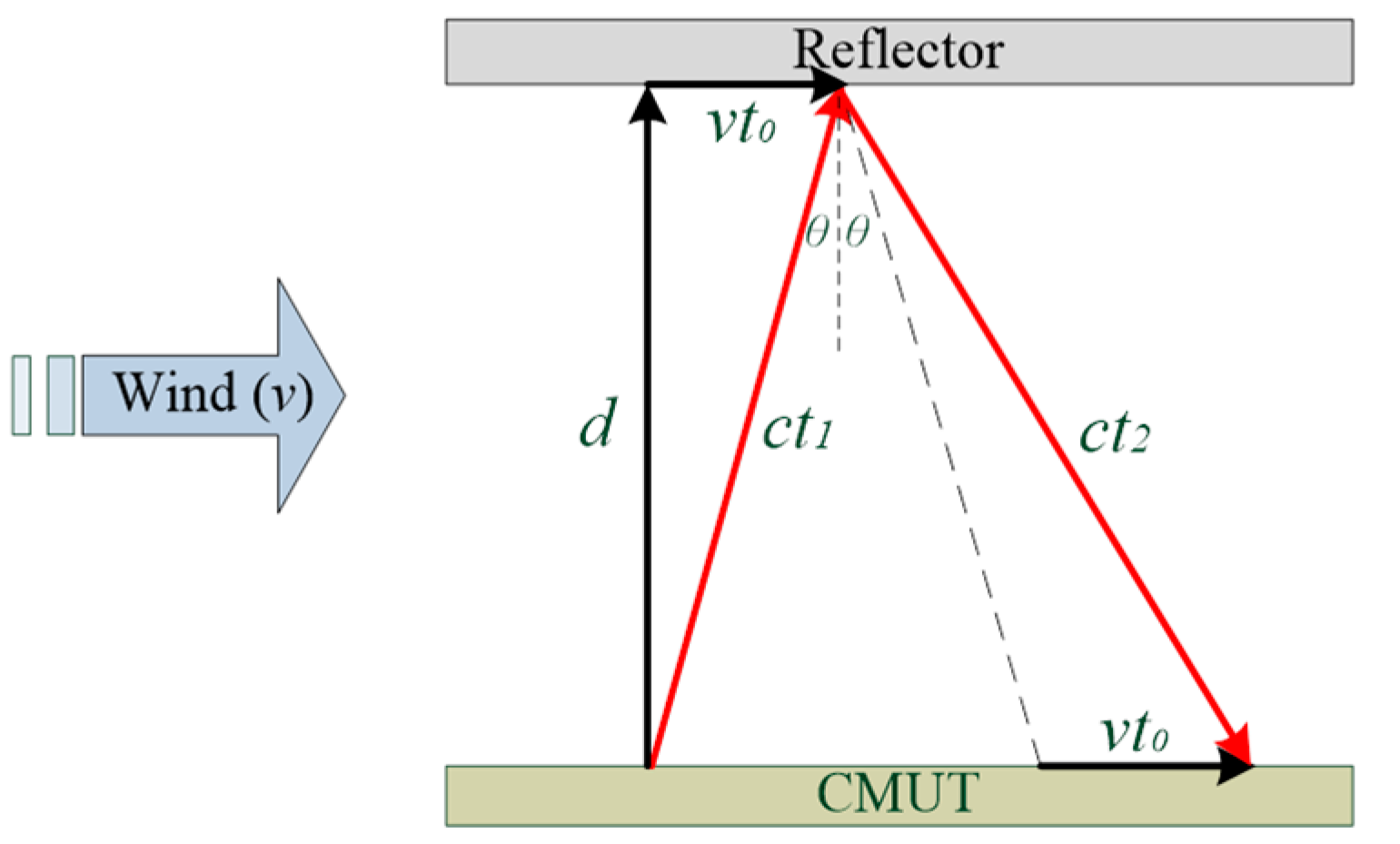
3.1. Measuring Wind Velocity
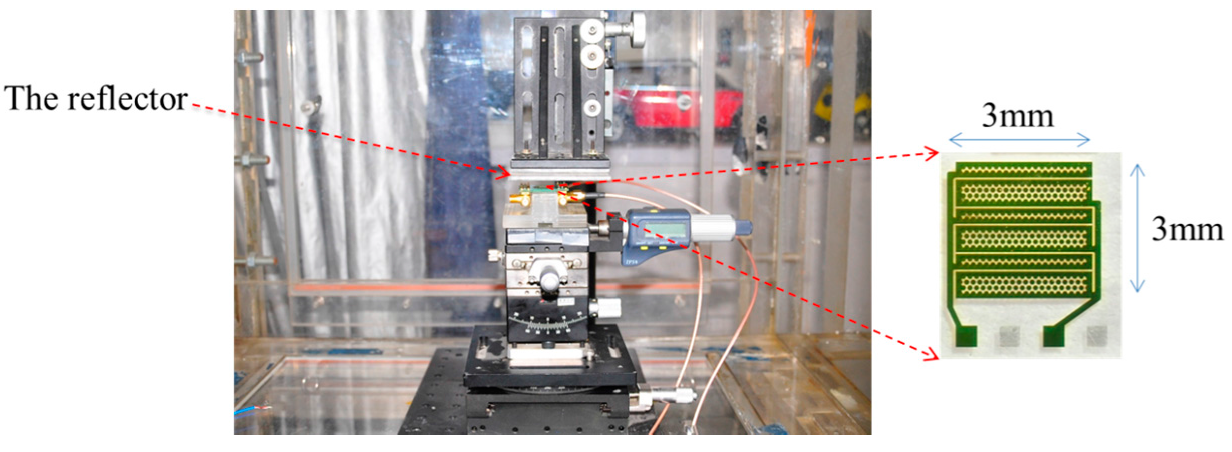
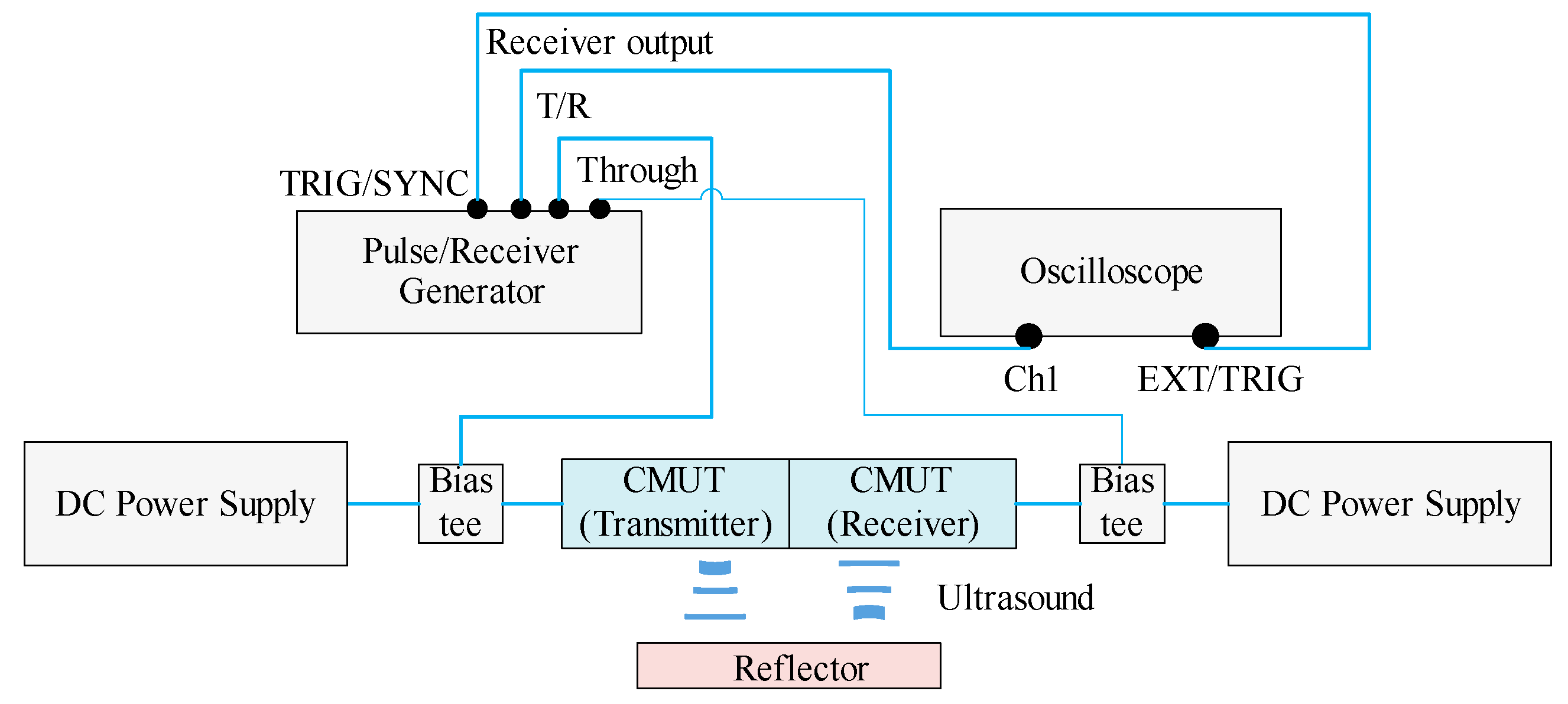
3.2. Wind Speed Measurement System Configuration
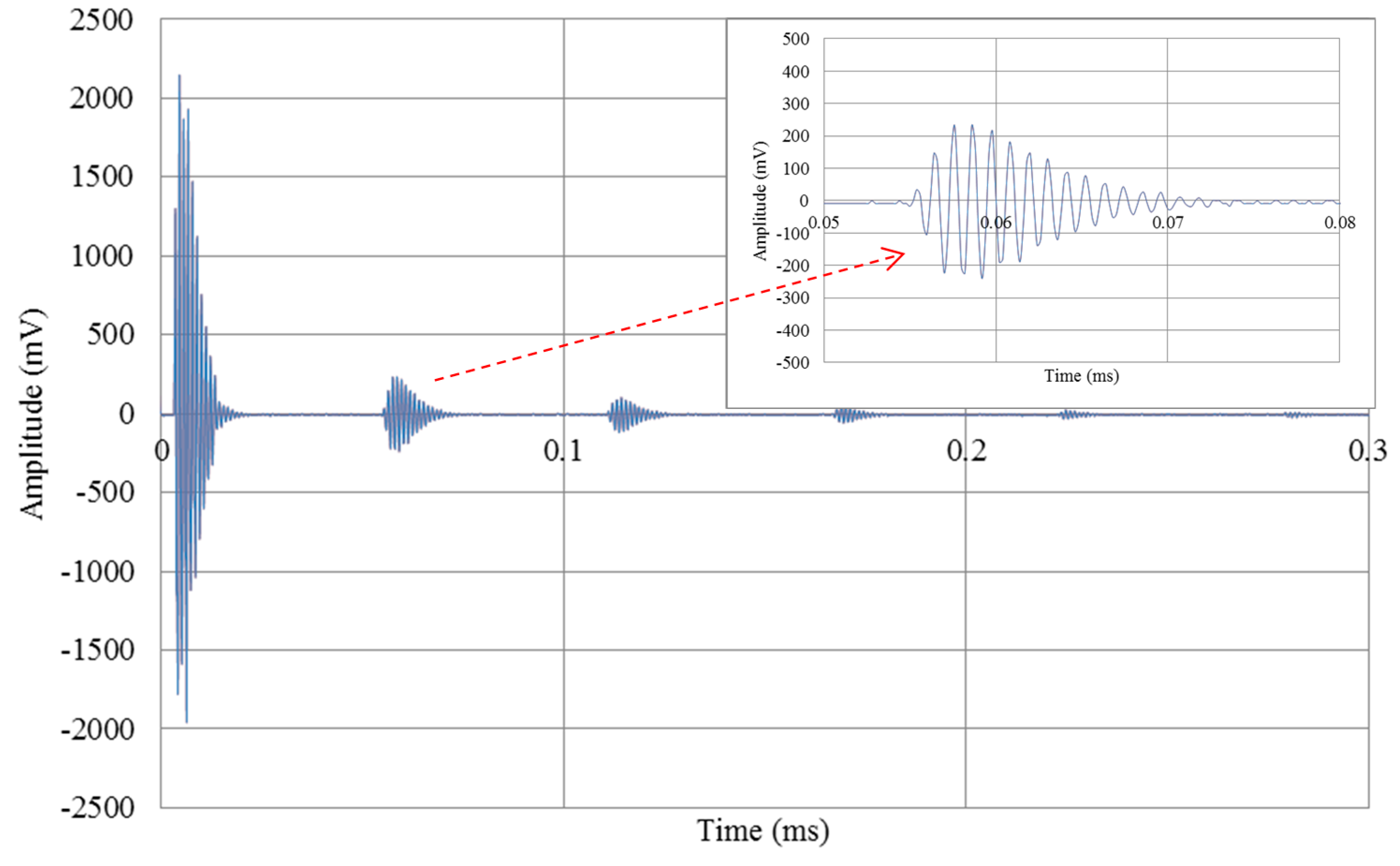
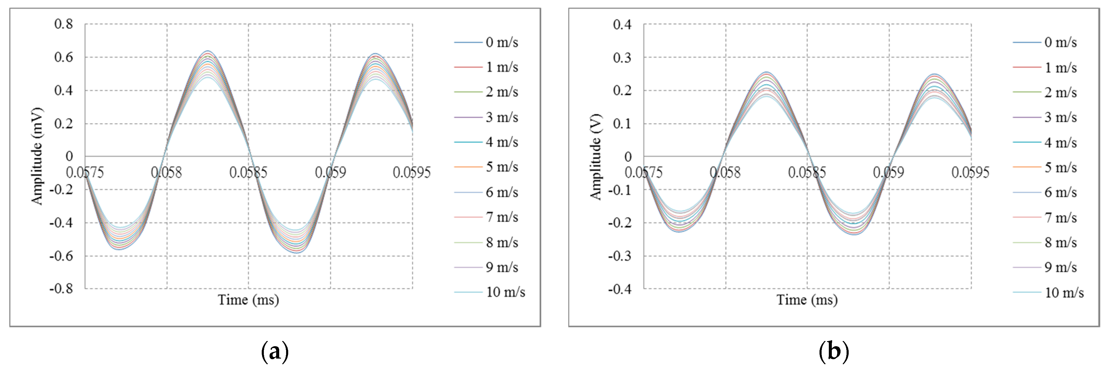
4. Experimental Results
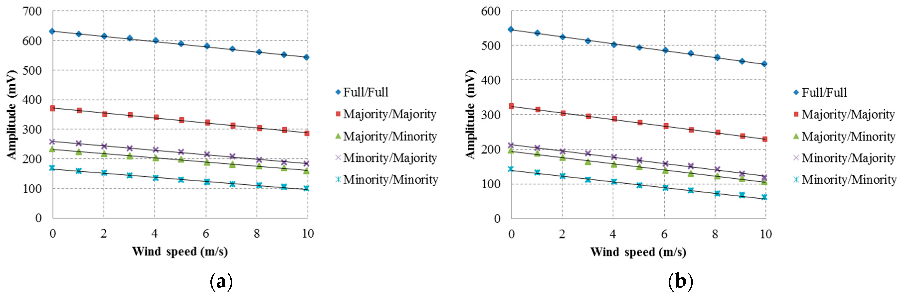
4.1. Using Amplitude of Signal to Measure Wind Speed
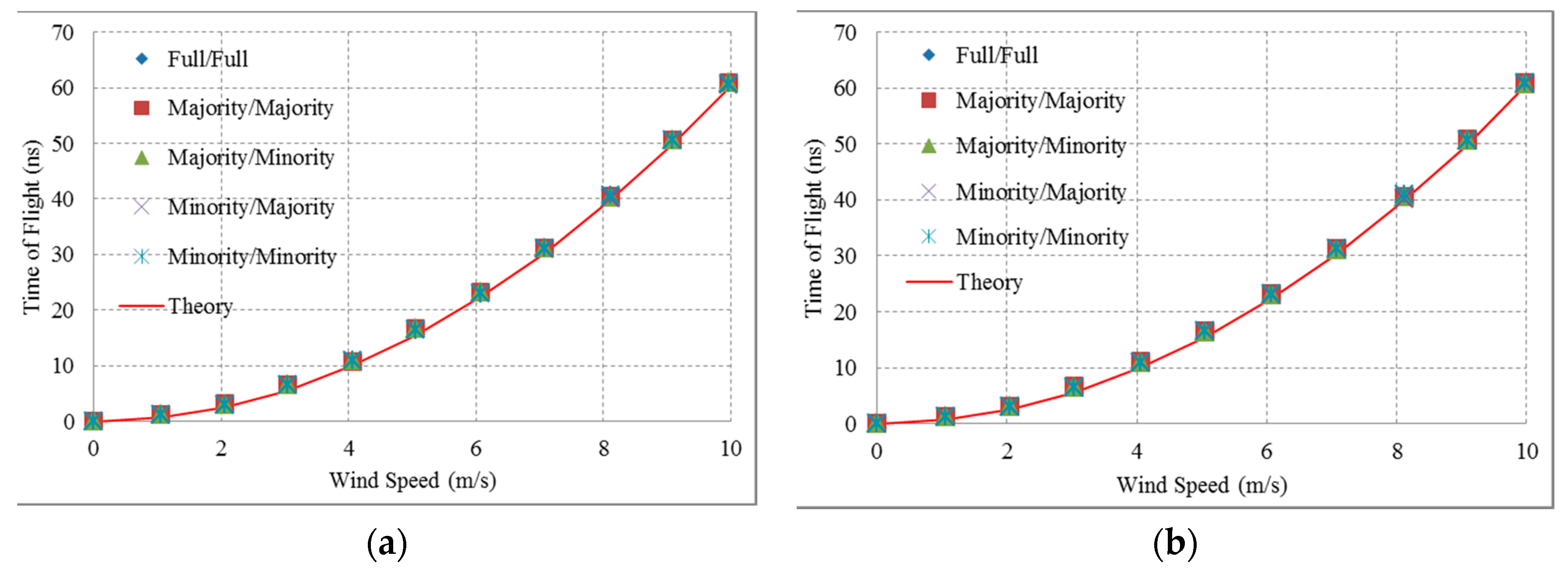
4.2. Using Differences in TOF’s to Measure Wind Speed
5. Conclusions
Acknowledgments
Author Contributions
Conflicts of Interest
References
- Haller, M.I.; Khuri-Yakub, B.T. A surface micro-machined electrostatic ultrasonic air transducer. IEEE Trans. Ultrason. Ferroelectr. Freq. Control 1996, 43, 1–6. [Google Scholar] [CrossRef]
- Ladabaum, I.; Khuri-Yakub, B.T.; Spoliansky, D.; Haller, M.I. Micro-machined ultrasonic transducers (MUTs). In Proceedings of the 1995 IEEE Ultrasonics Symposium, Seattle, WA, USA, 7–10 November 1995; Volume 1, pp. 501–504.
- Jin, X.C.; Ladabaum, I.; Degertekin, F.L.; Calmes, S.; KhuriYakub, B.T. Fabrication and characterization of surface surface micromachined capacitive ultrasonic immersion transducers. J. Microelectromech. Syst. 1999, 8, 100–114. [Google Scholar]
- Huang, Y.; Ergun, A.S.; Haeggstrom, E.; Badi, M.H.; KhuriYakub, B.T. Fabricating capacitive micro-machined ultrasonic transducers with wafer-bonding. J. Microelectromech. Syst. 2003, 12, 128–137. [Google Scholar] [CrossRef]
- Jin, X.C.; Oralkan, O.; Degertekin, F.L.; Khuri-Yakub, B.T. Characterization of one-dimensional capacitive micro-machined ultrasonic immersion transducer arrays. IEEE Trans. Ultrason. Ferroelectr. Freq. Control 2001, 48, 750–759. [Google Scholar] [PubMed]
- Bayram, B.; Oralkan, O.; Ergun, A.S.; Haeggstrom, E.; Yaralioglu, G.G.; KhuriYakub, B.T. Capacitive micro-machined ultrasonic transducer design for high power transmission. IEEE Trans. UFFC 2005, 52, 326–339. [Google Scholar] [CrossRef]
- Villanueva, J.M.; Catunda, S.Y.C.; Tanscheit, R.; Pinto, M.M.S. Wind speed measurement data fusion of phase difference and time-of-flight techniques using ultrasonic transducers. In Proceedings of the 2007 IEEE Instrumentation & Measurement Technology Conference IMTC 2007, Warsaw, Poland, 1–3 May 2007; pp. 1–6.
- Tong, C.; Figueroa, J.F. Guidelines for the use of ultrasonic noninvasive metering techniques. Flow Meas. Instrum. 2002, 13, 125–142. [Google Scholar]
- Lynnworth, L.C.; Liu, Y. Ultrasonic flowmeters: Half-century progress report 1955–2005. Ultrasonics 2006, 44, e1371–e1378. [Google Scholar] [CrossRef] [PubMed]
- Van Boxel, J.H.; Sterk, G.; Arens, S.M. Sonic anemometers in aeolian sediment transport research. Geomorphology 2004, 59, 131–147. [Google Scholar] [CrossRef]
- Catunda, S.Y.C.; Pessanha, J.E.O.; FonsecaNeto, J.V.; Camelo, N.J.; Silva, P.R.M. Uncertainty analysis for defining a wind power density measurement system structure. In Proceedings of the IEEE Instrumentation and Measurement Technology Conference, Como, Italy, 18–20 May 2004; Volume 2, pp. 1043–1047.
- Mauricio, J.M.; Catunda, S.Y.C.; Tanscheit, R. Maximum-likelihood data fusion of phase-difference and threshold-detection techniques for wind speed measurement. IEEE Trans. Instrum. Meas. 2009, 58, 2189–2195. [Google Scholar]
- Marioli, D.; Narduzzi, C.; Offelli, C.; Petri, D.; Sardini, E.; Taroni, A. Digital time-of-flight measurement for ultrasonic sensor. IEEE Trans. Instrum. Meas. 1992, 41, 93–97. [Google Scholar] [CrossRef]
- Espinoza, C.E.M.; Villanueva, J.M.M.; Catunda, S.Y.C. Wind speed measurement and uncertainty using ultrasonic sensor with Kalman filtering. In Proceedings of the Instrumentation and Measurement Technology Conference (I2MTC), Austin, TX, USA, 3–6 May 2010; pp. 624–628.
- Beck, M.S. Correlation in instruments: Cross correlation flowmeters. J. Phys. E: Sci. Instrum. 1981, 14, 7–19. [Google Scholar] [CrossRef]
- Wang, M.; Chen, J. Volumetric Flow Measurement Using an Implantable CMUT Array. IEEE Trans. Biomed. Circ. Syst. 2011, 5, 214–222. [Google Scholar] [CrossRef] [PubMed]
- Wang, M.; Chen, J.; Cheng, X.; Zhang, T.; Liu, X. A Bi-directional Real-time Blood Flowmeter Using an Implantable CMUT Array. In Proceedings of the 2008 IEEE Ultrasonics Symposium, Beijing, China, 2–5 November 2008; pp. 1–4.
- Hoffmann, M.; Unger, A.; Ho, M.C.; Park, K.K.; Khuri-Yakub, B.T.; Kupnik, M. Volumetric characterization of ultrasonic transducers for gas flow metering. In Proceedings of the 2013 IEEE International Ultrasonics Symposium (IUS), Prague, Czech Republic, 21–25 July 2013; pp. 1315–1318.
- Thranhardt, M.; Mooshofer, P.E.; Hauptmann, P.; Degertekin, L. A Resonant CMUT Sensor for Fluid Applications. In Proceedings of the 2009 IEEE Sensors, Christchurch, New Zealand, 25–28 October 2009; pp. 878–882.
- Bucci, G.; Ciancetta, F.; Fiorucci, E.; Gallo, D.; Landi, C.; Luiso, M. A Low-Cost Ultrasonic Wind Speed and Direction Measurement System. In Proceedings of the 2013 IEEE International Instrumentation and Measurement Technology Conference (I2MTC), Minneapolis, MN, USA, 6–9 May 2013; pp. 505–510.
- Han, D.; Park, S. A Study on Characteristics of Continuous Wave Ultrasonic Anemometer. In Proceedings of the 2011 IEEE Sensors Applications Symposium (SAS), San Antonio, TX, USA, 22–24 February 2011; pp. 119–122.
- Han, D.; Kim, S.; Park, S. Two-dimensional ultrasonic anemometer using the directivity angle of an ultrasonic sensor. Microelectronics 2008, 39, 1195–1199. [Google Scholar] [CrossRef]
- Raine, A.B.; Aslam, N.; Underwood, C.P.; Danaher, S. Development of an Ultrasonic Airflow Measurement Device for Ducted Air. Sensors 2015, 15, 10705–10722. [Google Scholar] [CrossRef] [PubMed]
- Bohn, D.A. Environmental Effects on the Speed of Sound. J. Audio Eng. Soc. 1988, 36, 223–231. [Google Scholar]
- Weast, R.C. CRC Handbook of Chemistry and Physics, 67th ed.; CRC Press: Boca Raton, FL, USA, 1986. [Google Scholar]
- Lofqvist, T.; Sokas, K.; Delsing, J. Speed of sound measurements in humid air using an ultrasonic flow meter. In Proceedings of the XVII IMEKO World Congress, Dubrovnik, Croatia, 22–27 June 2003; pp. 1650–1653.


| Parameter | Measurement (μm) |
|---|---|
| Membrane diameter | 140 |
| Membrane thickness | 5 |
| Sidewall width | 10 |
| Cavity height | 2 |
| Bottom electrode thickness | 0.05 |
| Top electrode diameter | 108 |
| Top electrode thickness | 0.15 |
| Mode | Wave-Type Design | Parallel-Line Type Design | ||
|---|---|---|---|---|
| Transmission/Reception (Cell Number) | Signal (mV) | Transmission/Reception (Cell Number) | Signal (mV) | |
| Full transmission/Full reception | 416/416 | 634 | 360/360 | 546 |
| Majority transmission/Majority reception | 274/274 | 362 | 240/240 | 324 |
| Majority transmission/Minority reception | 274/142 | 226 | 240/120 | 196 |
| Minority transmission/Majority reception | 142/274 | 244 | 120/240 | 214 |
| Minority transmission/Minority reception | 142/142 | 158 | 120/120 | 140 |
| Designs | Modes | Amplitude | TOF | ||
|---|---|---|---|---|---|
| Sensitivity (mV/ms−1) | Error (m/s) | Sensitivity (ns/(ms−1)2) | Error (m/s) | ||
| Wave-type CMUT | Full/Full | 8.807 | 0.198 | 0.617 | 0.153 |
| Majority/Majority | 8.379 | 0.254 | 0.616 | 0.154 | |
| Majority/Minority | 7.161 | 0.235 | 0.614 | 0.168 | |
| Minority/Majority | 7.555 | 0.272 | 0.617 | 0.161 | |
| Minority/Minority | 6.846 | 0.330 | 0.616 | 0.165 | |
| Parallel-line type CMUT | Full/Full | 9.906 | 0.189 | 0.618 | 0.155 |
| Majority/Majority | 9.552 | 0.180 | 0.616 | 0.156 | |
| Majority/Minority | 8.944 | 0.249 | 0.615 | 0.170 | |
| Minority/Majority | 9.166 | 0.241 | 0.617 | 0.165 | |
| Minority/Minority | 8.171 | 0.288 | 0.617 | 0.172 | |
© 2016 by the authors; licensee MDPI, Basel, Switzerland. This article is an open access article distributed under the terms and conditions of the Creative Commons Attribution (CC-BY) license (http://creativecommons.org/licenses/by/4.0/).
Share and Cite
Bui, G.T.; Jiang, Y.-T.; Pang, D.-C. Two Capacitive Micro-Machined Ultrasonic Transducers for Wind Speed Measurement. Sensors 2016, 16, 814. https://doi.org/10.3390/s16060814
Bui GT, Jiang Y-T, Pang D-C. Two Capacitive Micro-Machined Ultrasonic Transducers for Wind Speed Measurement. Sensors. 2016; 16(6):814. https://doi.org/10.3390/s16060814
Chicago/Turabian StyleBui, Gia Thinh, Yu-Tsung Jiang, and Da-Chen Pang. 2016. "Two Capacitive Micro-Machined Ultrasonic Transducers for Wind Speed Measurement" Sensors 16, no. 6: 814. https://doi.org/10.3390/s16060814
APA StyleBui, G. T., Jiang, Y.-T., & Pang, D.-C. (2016). Two Capacitive Micro-Machined Ultrasonic Transducers for Wind Speed Measurement. Sensors, 16(6), 814. https://doi.org/10.3390/s16060814