Abstract
Wireless sensor networks (WSNs) can gather in situ real data measurements and work unattended for long periods, even in remote, rough places. A critical aspect of WSN design is node placement, as this determines sensing capacities, network connectivity, network lifetime and, in short, the whole operational capabilities of the WSN. This paper proposes and studies a new node placement algorithm that focus on these aspects. As a motivating example, we consider a network designed to describe the distribution of helium-3 (He), a potential enabling element for fusion reactors, on the Moon. He is abundant on the Moon’s surface, and knowledge of its distribution is essential for future harvesting purposes. Previous data are inconclusive, and there is general agreement that on-site measurements, obtained over a long time period, are necessary to better understand the mechanisms involved in the distribution of this element on the Moon. Although a mission of this type is extremely complex, it allows us to illustrate the main challenges involved in a multi-objective WSN placement problem, i.e., selection of optimal observation sites and maximization of the lifetime of the network. To tackle optimization, we use a recent adaptation of the ant colony optimization () metaheuristic, extended to continuous domains. Solutions are provided in the form of a Pareto frontier that shows the optimal equilibria. Moreover, we compared our scheme with the four-directional placement (FDP) heuristic, which was outperformed in all cases.
1. Introduction
Fusion is attracting increasing attention, as unlike fission reactions, fusion reactions do not generate radioactive waste. Fusion reactors are designed to mimic nuclear reactions produced in the Sun by forcing together the nuclei of two hydrogen isotopes: tritium and deuterium [1]. The byproducts are energy, helium and high-energy neutrons, which are a containment risk [1,2]. This obstacle, however, can be overcome by substituting tritium for helium-3 (He). He is a single neutron isotope of helium produced naturally through hydrogen fusion in the Sun. Unfortunately, the Earth’s atmosphere and its magnetic field repel this element, and only traces of this element exist on Earth. The Moon, by contrast, has accumulated large amounts of He on the uppermost layer of its surface [3] (lunar regolith), bringing researchers on Earth to consider the possibility of mining this element from the Moon [4,5,6].
An endeavor of this magnitude, however, would require detailed planning and, of course, knowledge about the distribution and abundance of He on the Moon. Estimations of He abundance and distribution rely on parameters, such as solar wind flux, lunar regolith composition and maturity, lunar regolith grain size and regolith thickness. The compilation of all of these variables in a system model makes He estimation an extremely complex task. Indeed, existing He distribution and reserves models are marked by critical discrepancies due to imprecise or insufficient lunar data [7]. More accurate estimations would require large-scale, more detailed on-site surveying. Recent studies by Prasad and Murty [8], Pabari et al. [9] and Zhai et al. [10] have brought attention to the potential of wireless sensor networks (WSNs) for geological and mineral analysis on the Moon. In this paper, we focus on this scenario as a motivating example to evaluate a novel algorithm for optimal WSN placement.
WSNs are considered an enabling technology for unattended, long-lasting and rough terrain monitoring and have been widely studied in recent years [11,12]. They are constituted by multiple, small, relatively inexpensive nodes, which gather and relay environmental data to sink nodes, which in turn, forward this data to control centers. In any realistic WSN deployment, the placement of nodes must be carefully planned to ensure they are located in the best possible observation sites and to maximize the quality of the information gathered. In our proposed lunar He survey, it is critical to select sites that would improve the chances of obtaining trustworthy information on He distribution and abundance. Such a decision would normally be made on the basis of previous studies that have either directly or indirectly assessed the quality of each site. In our case, however, there are no maps available that directly characterize He distribution, although in recent works, authors, such as Li et al. [7], Slyuta et al. [13], WenZhe and YaQiu [14] and Zheng et al. [15], agree that there might be a direct correlation between TiO and He abundance. In Section 5.1 of the paper, we therefore consider a two-dimensional target area in which non-uniform mapping of TiO indicates the suitability of each site for He characterization. These maps can either offer a finite set of candidate sites (discrete placement) or place no constraints on placement (continuous placement). We focus exclusively on the latter case, since discrete placement is much simpler and has already been studied in depth [16,17].
Maximal spatio-temporal resolution is also desirable in geological surveys. On the one hand, this implies minimal separation between nodes to avoid redundant information, and on the other hand, it places a limit on maximal separation, as nodes need to establish radio-communication links with each other. In general, placement must guarantee network connectivity, i.e., it must guarantee the establishment of routes for conveying information to the sinks. Both questions are considered in our lunar example: minimal separation is addressed by using nodes with a sensing range, while connectivity is a constraint imposed on the problem.
Energy is also a major consideration in WSN placement. Access to battery replacements may be cost-prohibitive (e.g., polar surveys) or even impossible (e.g., a lunar survey) in hostile environments. Alternative sources, such as solar panels, are not always feasible (a lunar night, for example, lasts ∼14 Earth days), but may offer chances for recharge. For our scenario, energy efficiency should be explicitly included in the design of the WSN to prevent battery outages. Naturally, however, this goal must be balanced against another major concern: data quality. The bulk of WSN energy is consumed during radio communications, i.e., during transmission and reception (either of actual messages or idle listening). Therefore, we consider that energy consumption should be determined by the amount of data generated by each node (directly related to the quality of the site) and the “length” of the path (in hops) to the sink.
In brief, our proposed optimization scheme has two objectives: (i) to maximize the chances of obtaining good He distribution data and (ii) to minimize energy consumption. Finding exact solutions to problems of this type can be a daunting task given the complexity and, in many cases, may even become computationally intractable [18]. One solution chosen by many authors to find near-optimal solutions to multi-objective deployment problems is the use of metaheuristic algorithms (see Section 2), which is very much still an open research area. In our case, we drew on research by Socha and Dorigo [19], which extends the ant colony optimization (ACO) metaheuristic (see Dorigo et al. [20]) to handle continuous domains. This algorithm is termed , and to our knowledge, this is the first time it has been applied to a WSN deployment problem. Our approach is intended to be more realistic than previous, related studies in several respects:
- (1)
- The proposed deployment model considers coordinates as continuous variables.
- (2)
- We explore the novel use of the metaheuristic in a deployment problem and a multi-objective optimization problem. The literature on deployment problems in relation to ACO is limited, and we are faced thus with an open area of research. In addition, our work is the first ACO-related research to use preferential sensing coverage.
- (3)
- We present an original application scenario. Multi-objective deployment problems to date have mostly been applied to small-gridded, artificially-developed scenarios (see Section 2). We, by contrast, test our approach on a large extension of the Moon surface containing traces of He: the Dionysius region.
- (4)
- We have adjusted parameters of the algorithm to the deployment problem. This procedure and the resulting optimization model could be extended to other target scenarios and optimization objectives.
- (5)
- We evaluated the proposed deployment methodology by comparing to a simple heuristic in terms of coverage. A tradeoff between joint-coverage and energy cost is also computed, which could be useful when planning a lunar exploration mission.
The remainder of this paper is organized as follows. Section 2 introduces related work. Section 3 presents the deployment problem and formulates it as a multi-objective optimization problem. Section 4 overviews the algorithm. Section 5 describes our target scenario and the results achieved. Finally, Section 6 concludes the paper.
2. Related Works
In-depth reviews of the use of metaheuristics for WSN deployment problems are presented by Deif and Gadallah [16] and Tsai et al. [18]. In the latter case, the authors differentiate between metaheuristic algorithms that look for a solution in one and only one direction (in multi-variable space) at each iteration, such as tabu search or simulated annealing, and metaheuristics capable of searching in more than one direction at a time (population-based algorithms). These include evolutionary algorithms and swarm intelligence, which we focus on in the next section.
Swarm-based algorithms have been used to address multi-objective optimization deployment problems in recent years. These metaheuristics are inspired by the resilient property of certain biological species to collectively solve complex tasks (swarm intelligence). For instance, the ability of ants to find the shortest path to food inspired the development of ACO [21], while bird-flock movements during foraging led to the development of particle swarm optimization (PSO) [22]. These methods have outperformed common node placement techniques. Banimelhem et al. [23] and Pradhan and Panda [24], for example, use a genetic algorithm and binary particle swarm optimization method, while Liao et al. [25] compare virtual forces and glowworm swarm optimization, and Yu et al. [26] use artificial bee colony (ABC) optimization. A comparison deployment study performed by Mini et al. [27] shows how ABC outperforms PSO in terms of prolonging network lifetime. The paper by Sengupta et al. [28] introduces a fuzzy dominance-based decomposition technique in a multi-objective evolutionary algorithm that improves results obtained with PSO and simple genetic algorithms.
ACO has been widely applied to several networking problems, such as routing problems, as pointed out in the work of Kulkarni et al. [29]. For example, Cheng et al. [30] focus on network lifetime extension. Saleem et al. [31] deal with network hole minimization (i.e., the minimization of unconnected parts), whereas in [32], the same authors focus on optimizing delay, packet loss and power consumption. Lin et al. [33] and Ye and Mohamadian [34], in turn, propose mechanisms to eliminate redundancy by combining data from different sources in order to improve performance. In a recent study, Liu [35] presented an optimal distance-based transmission strategy to improve network lifetime. All of these works show that ACO-based solutions provide flexible and sound routing solutions. However, until now, ACO has been barely used to address deployment problems in WSNs.
Several studies [36,37,38,39,40,41] have attempted to formulate deployment as a multi-objective discreteoptimization problem with the application of ACO. In [36], the deployment aims to achieve full coverage in a gridded region with a minimum number of nodes. The authors employed a variant of ACO (Max-Min Ant) to solve the problem and showed that it can improve genetic-based algorithms in terms of the number of sensors. In [37], the authors presented a modified ACO algorithm to adjust the solution to different situations in the convergence process. The goal in [38] is to deploy sensors along a grid to cover points of interest while maintaining network connectivity. This procedure is similar to the local search method proposed by Rebai et al. [42] and to the four-directional placement (FDP) heuristic described in Section 5.1, which we use as a reference proposal. In addition, the authors use non-uniform node deployment to place more nodes in areas with a heavier load, thus increasing lifetime as a trade-off for deployment cost. By contrast, the ACO system approaches described in [39,40,41] only address optimization of network energy resources. Liao et al. [39] adapt ACO to solve a multi-knapsack problem, where energy is a resource that must be optimized among clusters of sensors. Anil Kumar and Thomas [40], in turn, use ACO to select optimal sub-sink nodes in order to minimize energy cost when transmitting to a mobile sink. Finally, Lin et al. [41] maximize network lifetime by using ACO to compute optimal clustering of the network while maintaining full coverage. None of these ACO deployment problems consider the continuous domain of node positions, or use , and in addition, they all target discrete or gridded areas that, unlike our lunar example, are unrealistic.
Other non-ACO multi-objective node placement-related approaches are described in [43,44,45,46,47,48,49,50]. Like us, the authors consider a deployment area characterized by the spatial irregularity of the sensed event. The goal of works [43] and [44] is to find global Pareto-optimal solutions to a multi-objective deployment problem with coverage, connectivity and lifetime constraints. Two heuristics are proposed: an adaptation to several objectives of the tabu search metaheuristic and a virtual potential field algorithm. Sengupta et al. [48] use the same multi-objective optimization methodology as in [28] to achieve maximum lifetime and coverage. In this case, instead of dealing with traditional grid or uniform coverage, the authors focus on probabilistic coverage in regions that require different levels of sensing. In these works [43,44,48], tests are developed in small, artificially-generated scenarios. The authors of [45,47,50] also use small test scenarios, but in this case, they are more realistic. In [45] and [47], the authors present a novel hybrid scheme based on geostatistical analysis and the Monte Carlo technique. The aim is to find optimal sites with the minimum averaged variance of the measured phenomena. Deployment tests are performed with realistic data: mercury in soil outside Oak Ridge Reservation in [45] and chromium contamination at Los Alamos National Laboratory in [47]. None of the works [45,46,47,49] address the optimization of energy costs. One algorithm that does address energy cost is that presented by González-Castaño et al. [50], whose aim is to locate shots in a national park to detect poaching. Node sites are selected for maximal sensing coverage and minimal installation cost (related in this case to distance to power lines). Nonetheless, the optimization methodologies used in [45,47,49,50] are not bioinspired.
In short, the literature on multi-objective deployments using ACO is scarce. In the models described, node positions are restricted to a finite set of candidate sites (discrete optimization), and tests are undertaken in small artificial scenarios. Furthermore, none of the ACO deployment studies reviewed consider irregularities in sensing coverage. We, by contrast, tested our model for use in a large realistic deployment scenario (the Moon), where positions can be selected from a continuous set. We used , a new ACO metaheuristic, for continuous variables. To our knowledge, this metaheuristic has not been used before in either single- or multi-objective deployment problems.
3. WSN Deployment Model
Our model comprises a set of N nodes (including a base/sink node per network). Let us recall from Section 1 that the WSN must be deployed in a target area where placement sites have a non-homogeneous quality. The goal is to maximize the importance (information about He distribution) obtained. In other words, sites expected to contain higher traces of He are more importantthan sites with lower estimations of He traces. The planning is subject to communication constraints, as well, since nodes must have a path (either direct or indirect via a multi-hop route) to the sink node. Figure 1 illustrates the main elements of the model.
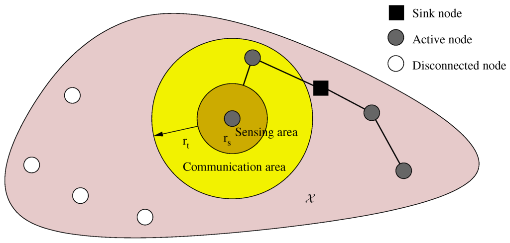
Figure 1.
Connectivity and sensing parameters.
Formally, let a region represent the target area. There exists an importancemapping (representing expected He distribution) associated with every point , which is defined by a real function . A solution is a set containing the position of nodes, , and is the set of all (candidate) solutions. Besides, the following considerations have been established:
- The hardware of the nodes is homogeneous, i.e., it is of the same type and has the same communication/sensing capabilities.
- The sink node can be any of the N sensor nodes. Without loss of generality, we assume that it is Node 1 and is therefore positioned at .
- The dimension of our problem is , since a solution is composed of positions of N nodes in an space.
- The sensing range is the minimum significant separation required between two nodes to consider their sensing data independent. The information gathered by sensor i is then given by:where is the open ball in centered in x with radius r. Figure 2 depicts this model.
- The transmission range is the longest separation distance between two mutually communicating nodes, and it determines network connectivity. Let us term active nodes all nodes able to transmit their sensed data to the sink, and let A denote this set of nodes.
3.1. Coverage Objective: Importance
If sensing areas of active nodes overlap, the information gathered is counted only once, since as stated above, it is not independent. In other words, the open set describing the sensed area is:
Thus, the sensing is given by ,
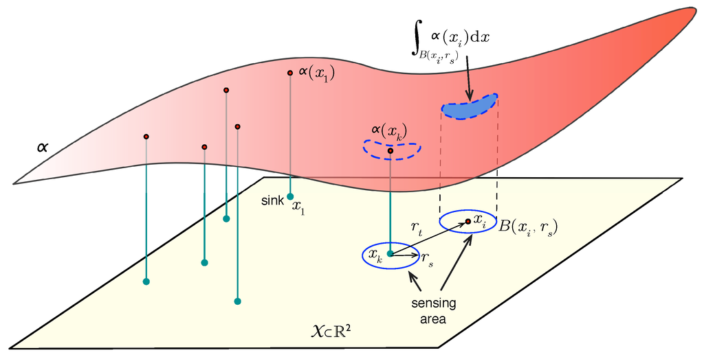 which measures the importance (i.e., information about He) covered by the nodes and which we aim to maximize.

Figure 2.
Problem description.
3.2. Energy Objective: Cost
Energy efficiency is another important factor that must be taken into account. As stated previously, it is mandatory to reduce global energy consumption. In our model (see Figure 3), we assume the shortest hop-count path routing, as well as an anti-collision layer based on a duty cycle with on/off periods. Both strategies are common in WSNs [51].
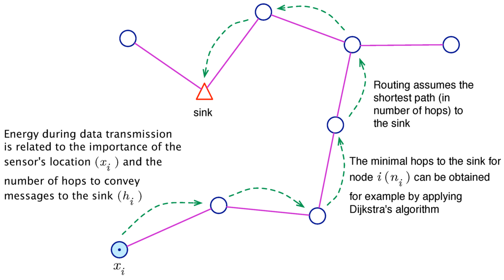
Figure 3.
Routing of messages generated by node towards the sink.
In WSNs, energy consumption is mostly due to message transmission/reception, and other sources of waste, such as CPU load or electronics sensing, have only a minor impact [52]. With the assumption of an operation in a duty cycle, nodes turn on the radio during the active stage for the transmission and reception of messages. The energy used depends on the number of transmitted messages. In our model, we reasonably assume that more important places cause more transmission events, and therefore, transmission consumption is proportional to if the node is placed at x. In addition, the routing of the node also plays a central role in energy consumption, since the messages must be retransmitted by intermediate nodes on their way to the sink. Let denote the number of hops on the minimal hop-count route from node i to the sink. Then, the energy associated with the transmission of a node i can be expressed as , where is constant and represents the energy used per message (assuming constant-length messages).
Finally, the reception consumption is considered constant (let denote it) in most WSN models [53], since radios are permanently on during the active part of the duty cycle. That is because it is not possible to forecast when incoming messages will arrive. From this perspective, an expression for energy consumption in the WSN can be obtained directly as follows:
Since the goal is to minimize this function, constants and can be safely removed from the optimization problem description, leading to:
Note also that because Node 1 is the sink.
3.3. Multi-Objective Deployment Problem
Our ultimate task is to place N sensors such that the information covered, , is maximized and the energy cost, , is minimized. Clearly, both objectives are contradictory and must be balanced: function selects positions with more information about He, whereas tends to concentrate nodes close to the sink. For that reason, it is desirable to produce a Pareto front [54] for these two goals. A Pareto front is a set of non-dominated solutions and represents a pool of candidate optimal solutions, which allow the establishment of optimal trade-offs in the problem balance.
This joint problem can be stated as:
The Pareto front can be obtained by solving problem Equation (5) repeatedly, assigning values to . As mentioned, it is a set of non-dominated solutions, that is solutions where the value of cannot be improved without worsening the value of , and vice versa. Examples in Section 5.2 show the Pareto front obtained in our lunar survey example. The next section describes our optimization model based on .
4. Optimization Methodology
ACO is a metaheuristic for combinatorial optimization (i.e., discrete domain problems). It is inspired by the foraging behavior of real ants, proposed by Dorigo et al. [20]. In ACO, ants build candidate solutions while exploiting search experiences and problem knowledge, represented by coefficients (pheromones and heuristic information, respectively) associated with each solution. Once an ant completes a new solution (at each iteration of the algorithm), the pheromones are updated to direct the ants towards the most promising regions of the search space. These algorithmic activities, namely (1) construction of ant-based solutions and (2) pheromone updating, are the main constructs of the ACO. [19] also maintains this structure, but adapts it to the continuous domain of the variables. Basically, the idea underlying is the shift from a discrete probability distribution to a continuous distribution to generate new solutions.
uses a solution archive to store former solutions (see Figure 4) and their corresponding pheromone information. Each solution in T is a real-valued -dimensional vector corresponding to coordinates of the N nodes in . A solution is an N-bivariate vector in , which stores site positions. New solutions are obtained as samples of a continuous random vector whose distribution function is determined from the previous solutions and their pheromone level. This process is explained in the next section.
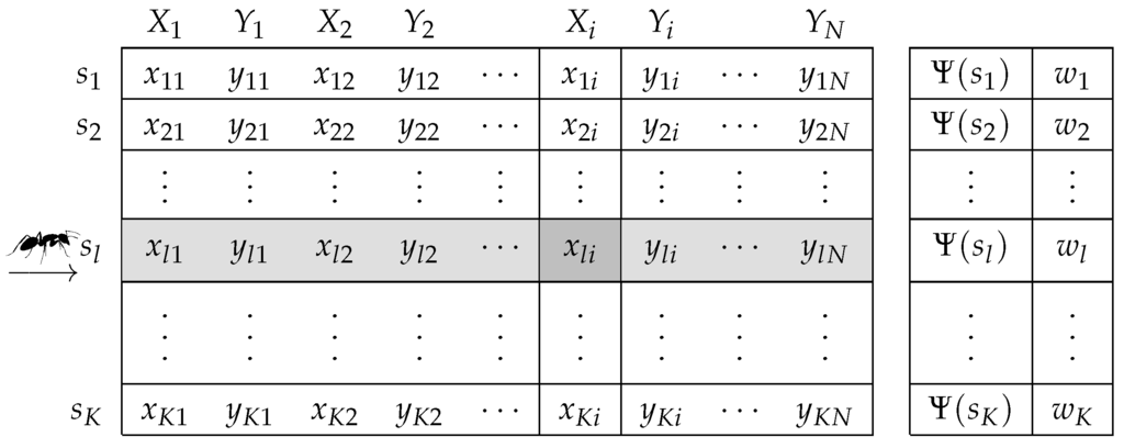
Figure 4.
Solution archive (T) used by in the placement optimization problem.
4.1. Initialization
Our placement optimization algorithm begins by initializing the solution archive with K solutions , generated randomly. These solutions are ranked in T ( the best and the worst) according to their objective function value, in our case expressed by Ψ in Formula (5). Besides, each solution has an associated weight, which is computed as:
where l is the rank of solution . The operational parameter q modulates the chance of selecting each row in T. In other words, when q is small, the best-ranked solutions are strongly preferred, and when it is large, the probability becomes more uniform. Since the w’s are used by the ants to make probabilistic decisions on how to sample the search space, they are providing the heuristic information of the algorithm. Initialization is the first step of the algorithm, as shown in Figure 5. At this point, we also set p number of ants, each of which is in charge of constructing a complete solution at each iteration.
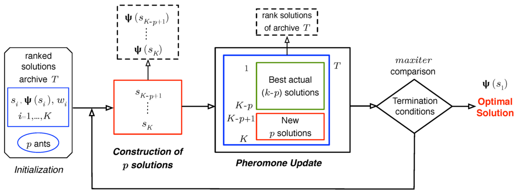
Figure 5.
main loop scheme.
4.2. Construction of Ant-Based Solutions
To compose a new solution, a sample for each i-th random component and (Figure 4) is computed. The distribution function of is given by:
where are Gaussian random variables:
the means of which become , and are their standard deviations. The elements are the weights Equation (6) associated with each ranked solution in archive T. components are obtained similarly.
A simple procedure to generate samples of random variables of the type in Equation (7) is the composition method [55]. First, a row l in T is selected. Each row l has a probability in this selection. Then, for each , sample functions and .
The standard deviations of these Gaussians functions are:
which is the average distance between the coordinate value (i-th node) of solution and the values of the respective coordinate of the other solutions in T multiplied by ξ. The standard deviations are computed similarly. Parameter ξ regulates the tendency of the ants to explore locations that have not yet been evaluated. The process of choosing a row and building a new candidate solution is repeated p times (corresponding to the number of ants) per iteration. Before the next iteration, the algorithm updates the solution archive, as we explain in the next section.
4.3. Pheromone Updating
Pheromone information is used by ants to reinforce promising solutions and bias the probabilistic decisions of other ants toward these solutions. As we mentioned earlier, pheromone is stored in T, and its content is updated at each iteration of the algorithm. This update is accomplished by adding the p newly-generated solutions to the solution archive T and removing the same number of worst solutions (see Figure 5). Solutions in T are then ranked before a new iteration is started. This process ensures that only the K best solutions are kept in the archive, so that they effectively guide the ants in the search process.
Eventually, the algorithm stops executing solution generation cycles when no improvements for the highest-ranked solution are found after a given number of iterations ().
5. Placement Algorithm Evaluation
5.1. WSN Planning Preliminaries and Lunar Target Area Selection
Among the different candidate lunar areas, we propose a closer study of the Dionysius region [56] by means of a WSN. The Dionysius region is located near the western edge of Mare Tranquillitatis (see Figure 6a) and is centered on the Dionysius crater (N, E), which has a diameter of 18 km. This region is known to have a high concentration of ilmenite material (FeOTiO), which is thought to contain He (Zheng et al. [15]).
Our aim is to deploy the WSN at the points where models have predicted a greater abundance of He. We assume that trustworthy points correspond to zones with TiO abundance (see Section 1), a good tracer of ilmenite. Therefore, a digital map of TiO content represents an indicator function corresponding to the presence of He and can potentially be used for our proposal.
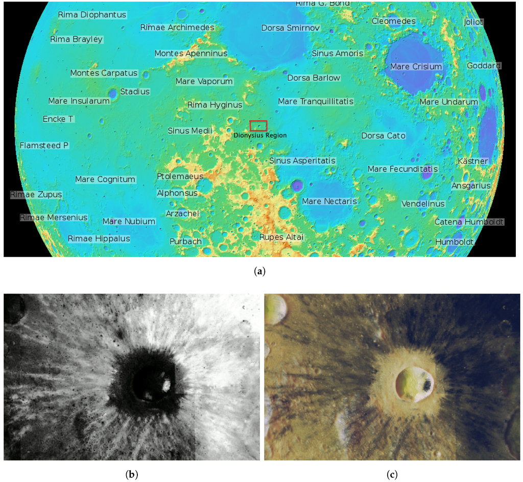
Figure 6.
Dionysius region of interest with coordinate values S 1.6 N4.2 and W15 E 19 in degrees. (a) NASA’s Lunar Reconnaissance Orbiter (LRO) Wide Angle Camera (WAC) relief image in orthographic projection of the lunar near side and the Dionysius region in the center. Source: http://wms.lroc.asu.edu/lroc; (b) percentage of TiO2 weight (wt%) using the Lucey et al. [57] method. Source: http://www.lpi.usra.edu/lunar/tools/clementine/; (c) the Dionysius region of interest with an overlay of TiO2 percentage in black tones.
We used an image map of TiO abundance in our area of interest, delimited by latitude S N and longitude W E and generated through the Clementine Mapping Project of the Lunar and Planetary Institute (LPI) [58] web service. The image size is pixels, and its scale is km/pixel in single cylindrical projection (plate carrée) [59] corresponding to an approximate surface of km. The weight percent (wt%) of TiO is computed based on the method described by Lucey et al. [57], as shown in Figure 6b, where brighter tones indicates higher Ti content (i.e., higher importance or estimated He). For the convenience of this work, the original RGB Figure 6b was color inverted and indexed, such that each pixel in the image has an associated value, ranging from zero for the whitest areas (minimum TiO abundance) to 255 for the darkest areas (maximum TiO abundance). It represents our importance function, as defined in Section 3, indicating the expected He distribution at each location. Figure 6c shows the resulting indexed image overlying a relief image of the same coordinates in simple cylindrical projection obtained from the Lunar Reconnaissance Orbiter Camera [60].
Without loss of generality, we can make the following practical considerations for the deployment:
- Excluding the centered Dionysius crater, the region of deployment is smooth enough to be considered a flat surface (i.e., it is not rugged). Although there may be some He inside the crater, the amounts are small and distant from other parts of the scenario and, thus, can be ignored.
- The maximum number of sensor nodes has been restricted to , because spacecraft payload capacity is always limited [61]. In order to scatter these nodes in our huge target area, parameter needs to be adjusted. In our tests, we have set a long transmission range km.
- Antennas are assumed to be omnidirectional dipoles placed at sufficient height above the Moon surface to ensure that signal propagation (reflection, diffraction, penetration, etc.) is not affected by ground effects. Under these conditions, the propagation model on the lunar surface could be approximated to the free-space model, even for long-range distances [62,63].
- We assume that the transmission power of our nodes may be adjustable between dBm and dBm; we also assume a carrier frequency of MHz. This frequency allows reduced antenna dimensions of cm, which are suitable and easy to manage in space applications and also require less energy consumption than higher operation frequencies.An estimation of the received power at a 6-km distance can be computed using the well-known Friis equation [64].For instance, if we select a transmitting power of dBm (assuming typical dipole gains and a system loss factor of ), then we obtain a received power of dBm. Commercial transceivers of these characteristics are easily available [65].
- The sensing range is set to km (15 pixels in Figure 6c).
- The deployment of nodes on the lunar surface could be achieved using a rover, navigating the lunar surface. This scheme would allow controlled positioning of the nodes, although it might take a long time to put all of the nodes in place. Possible alternative methods include dropping the nodes from a spacecraft or launching them from a rover (Sanz et al. [66]).
5.2. Validation Tests
Based on adjustment tests in the deployment region, the following parameters were selected:
- Number of solutions within archive T: .
- Number of ants: .
- and .
- .
The better the tuning of , the better the algorithm will perform (higher objective function and lower computation time). For instance, the size K of the solutions table is critical because it determines the complexity of the pdfs that the ants have to sample to generate new solutions. This parameter has been tested for different network sizes (). Figure 7 shows the relative importance for and . The relative importance is defined as the ratio of the importance map covered Equation (3) to the total importance () contained in the map,
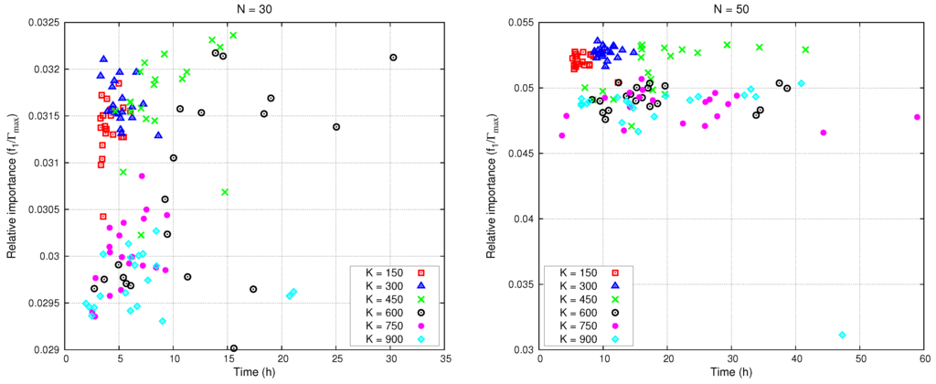
Figure 7.
Relative importance sensed and computing time.
Results for have the highest relative importance and the smallest computing time of the algorithm. All computations were performed on an 8-CPU Xeon E5 computer with 128 Gb of RAM. Table 1 and Table 2 collect WSN deployment and operating parameters, respectively.

Table 1.
Technical parameters.
| number of nodes | |
| transmission range | km |
| sensing range | km |
| transmitter power | dBm |

Table 2.
initialization parameters.
| T size | |
| number of ants | |
| heuristic parameter | |
| pheromone evaporation rate | |
| termination condition |
Next, we contrast our results with those obtained using a reference heuristic used previously in Rebai et al. [42], which for convenience we call four-directional placement (FDP). For this FDP heuristic, a grid is considered over the target area, with an space lattice. The FDP is an iterative algorithm, which starts at a random position. At each step, it selects the adjacent, previously unselected point of the grid with the highest importance, such that the network remains connected. Following the up, down, right and left directions, the adjacent points are evaluated at and distances from the current position. If several points have the same value, FDP chooses one at random. During this process, the points evaluated are kept in a sorted table (observed points table) in descending order of relevance. The top one is selected as the node position, and the process continues from this point. Note that this algorithm guarantees full connection of the network.
In our target area of Figure 6b, we considered the deployment of sensors and , evaluating the relative importance. These experiments were repeated 20 times ( deployment simulations) for each of these algorithms, and FDP. The relative importance is displayed in Figure 8a and the efficiency in Figure 8b, with a confidence level of .
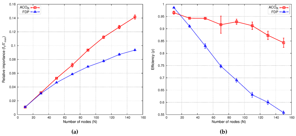
Figure 8.
Performance comparison of -based versus the four-directional placement (FDP) heuristic.
Efficiency ρ is computed as joint-coverage divided by the maximal information that can be sensed by N nodes. That is, , where is the maximum value of importance assigned to a point on the map. Efficiency provides insight into the quality of the deployment. Clearly, efficiency decreases with the number of nodes, since as network size increases, more nodes are used to gather less important data or simply to convey information from distant zones. Table 3 shows the maximum joint-coverage and the efficiency for different deployment instances, some of which () are depicted in Figure 9. The sensing coverage zone of each node is represented by a semi-transparent yellow circle; yellow lines are the shortest paths between the sink node (marked in white) and each node. Note that with , sensing zones do not overlap in order to maximize .

Table 3.
Maximum joint-coverage in deployments.
| Relative Importance () | Efficiency (ρ) | |||
|---|---|---|---|---|
| N nodes | FDP | FDP | ||
| 10 | 0.0110 | 0.0110 | 0.9919 | 0.9883 |
| 30 | 0.0321 | 0.0312 | 0.9568 | 0.9328 |
| 50 | 0.0535 | 0.0489 | 0.9581 | 0.8762 |
| 70 | 0.0741 | 0.0600 | 0.9478 | 0.7669 |
| 90 | 0.0947 | 0.0742 | 0.9415 | 0.7377 |
| 110 | 0.1150 | 0.0847 | 0.9356 | 0.6892 |
| 130 | 0.1346 | 0.0919 | 0.9265 | 0.6323 |
| 150 | 0.1533 | 0.0972 | 0.9142 | 0.5800 |
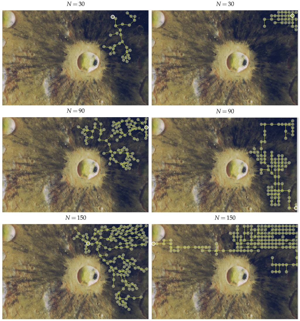
Figure 9.
Node placement examples for different numbers of nodes in the Dionysius region. (left) and FDP (right). Numerical results in Table 3.
The results of Figure 8 demonstrate that our -based algorithm outperforms the FDP heuristic, even in scenarios with few nodes. These figures show how with , joint-coverage grows steadily as the number of nodes increases. When the network is small (), the efficiency of and FDP is comparable. However, as the network size increases, maintains a high ρ, even for complex networks (e.g., at ), but FDP efficiency decreases steadily.
Figure 10 depicts the evolution of the algorithm convergence time versus the number of nodes and map size in both scenarios. We performed 50 tests with three different scenario sizes: , and pixels (reducing the original map size). As expected, increasing the number of nodes raises the convergence time, which grows almost exponentially for , but linearly for larger network sizes. Furthermore, results for have a higher variance in both scenarios.
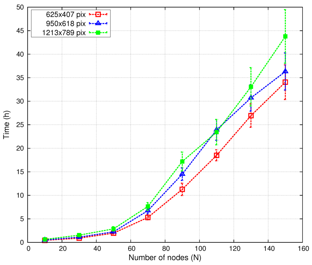
Figure 10.
Convergence time versus number of nodes (N) and scenario size.
Figure 11 shows the results of the Pareto front of functions and .
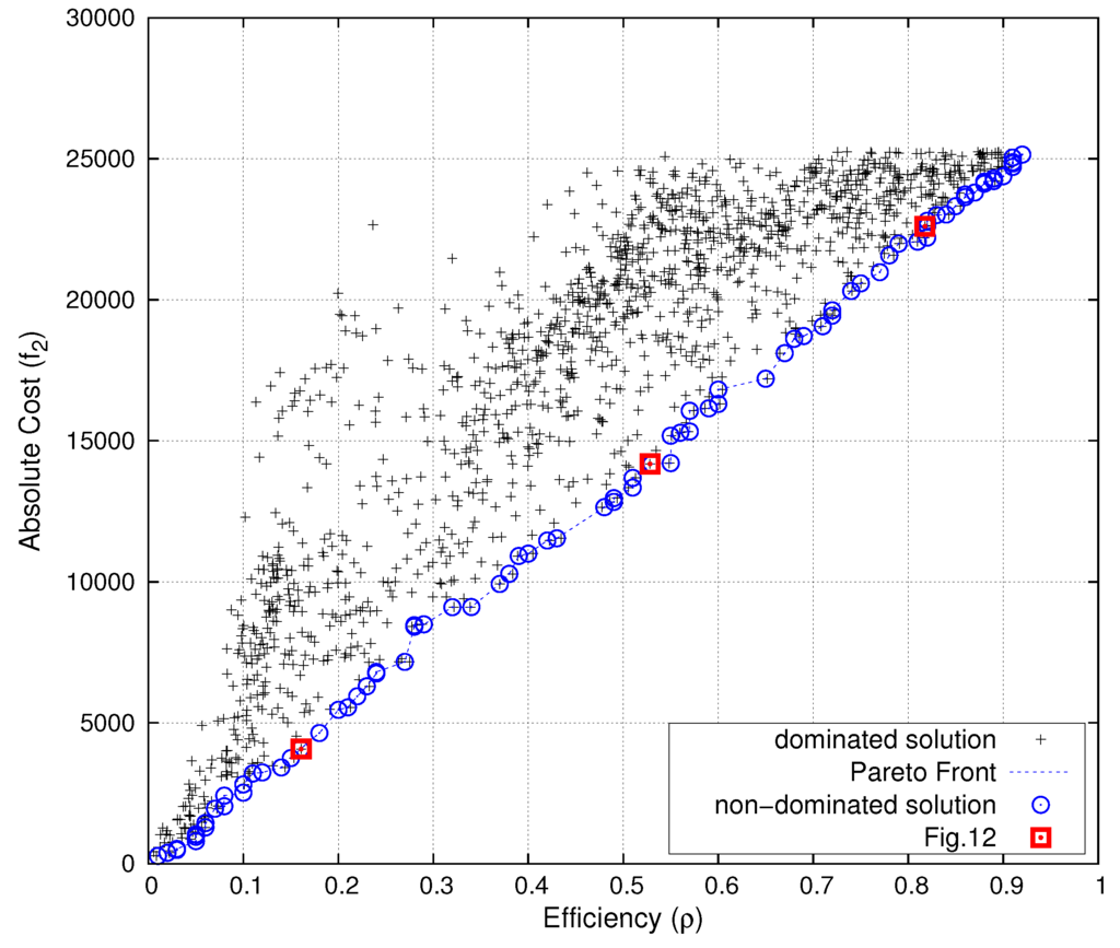
Figure 11.
Pareto front (in blue) of (network sensing coverage) vs. (network cost). Deployments of Figure 12 in red.
The solver was executed 2040 times, from different initial positions, selected at random. Figure 11 shows a subset of representative solutions of varying parameter θ. The blue line shows the “best solutions”, in the sense that it is impossible to improve one of the goals without worsening the other.
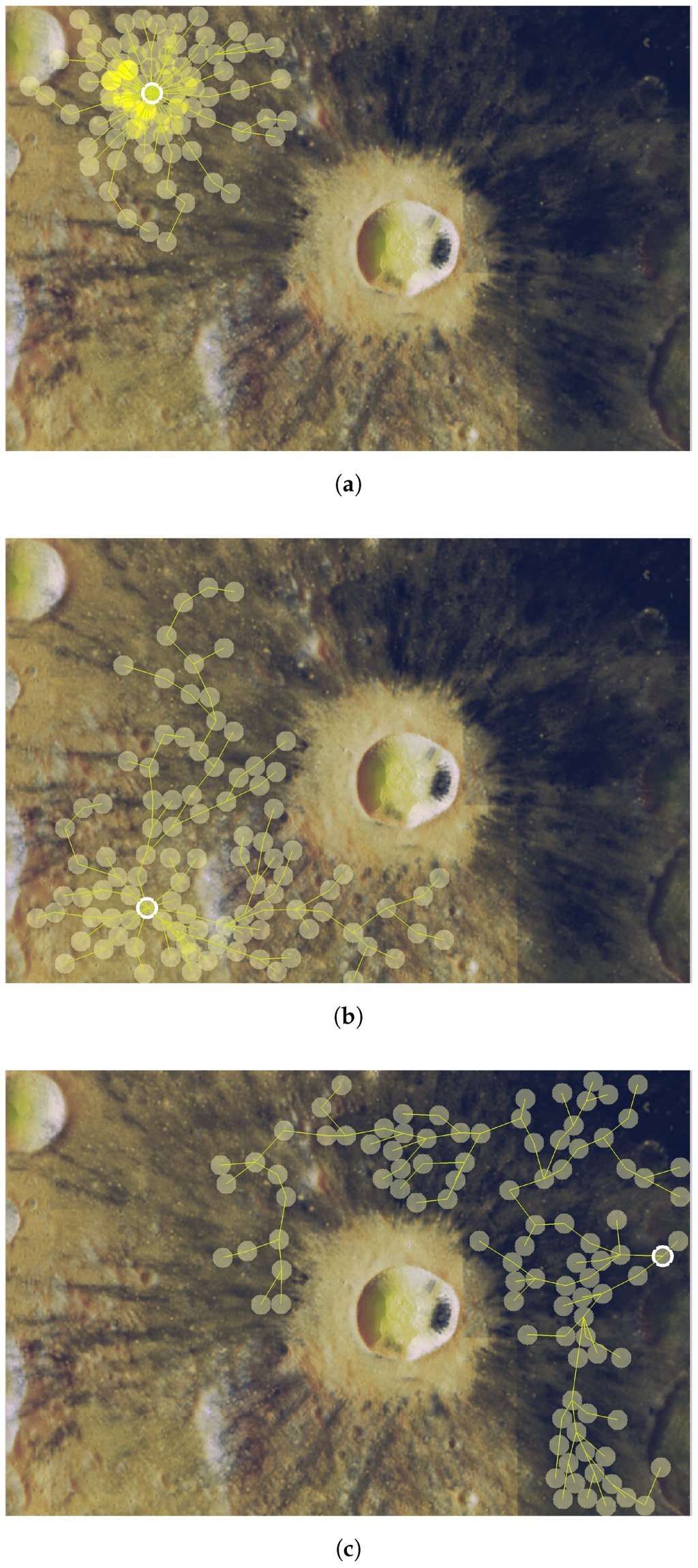
Figure 12.
Sensing coverage of TiO2 content in the Dionysius region of interest. (a) θ = 0.0025, f1/Γmax = 0.1608 and f2 = 4067; (b) θ = 0.05, f1/Γmax = 0.5282 and f2 = 14179; (c) θ = 0.36, f1/Γmax = 0.8176 and f2 = 22607.
The result reveals that the Pareto front approach is useful. The solution shows the tradeoff between cost and joint-coverage of the network. Cost is related to the energy consumed by the network during lunar nights (periods without direct sun exposure). Therefore, mission planners could compute battery consumption during lunar nights, combine this with other costs (variables of the mission), such as battery weight, performance, durability, and so on, and obtain optimal positions in terms of expected He abundance. Besides, the Pareto front results are linear, showing that there is an inverse proportional relationship between both optima magnitudes. Finally, Figure 12 also displays three sensor deployments in our region of interest for three choices of matching the red points on the Pareto frontier represented in Figure 11. This shows how several “optimal” solutions may behave distinctly, depending on the prioritized variable in the tradeoff balance.
6. Conclusions
We have developed a methodology based on the metaheuristic for sensor node placement and tested this algorithm against the FDP heuristic. outperformed FDP in all of the tests. The time consumed by the algorithm scales well with the size of the search space (number of nodes and map size).
We have also evaluated a concept mission for the deployment of the proposal in a lunar scenario. In the case of relatively large network sizes (most likely in missions of this kind), efficiency ρ was also superior with our -based algorithm.
The methodology developed in this paper can be easily extended to other complex placement problems, for example by including mass limitations or deployment time in the multi-objective function.
Acknowledgments
This work was supported by Project MINECO/FEDER TEC2013-47016-C2-2-R, COoperative INtelligence Schemes for FI emerging technologies (COINS).
Author Contributions
The author is responsible of this research.
Conflicts of Interest
The authors declare no conflict of interest.
References
- McCracken, G.; Stott, P. Fusion: the Energy of the Universe; Academic Press: Cambridge, MA, USA, 2012. [Google Scholar]
- Kovari, M.; Harrington, C.; Jenkins, I.; Kiely, C. Converting energy from fusion into useful forms. Proc. Inst. Mech. Eng. A 2014, 228, 234–240. [Google Scholar] [CrossRef]
- Crawford, I.A. Lunar Resources: A Review. Prog. Phys. Geogr. 2015, 39, 137–167. [Google Scholar] [CrossRef]
- Fusion Technology Institute. University of Wisconsin-Madison. Lunar Mining of Helium-3. 2014. Available online: http://fti.neep.wisc.edu/research/he3 (accessed on 29 October 2015).
- Simko, T.; Gray, M. Lunar Helium-3 Fuel for Nuclear Fusion Technology, Economics, and Resources. World Future Rev. 2014, 6, 158–171. [Google Scholar] [CrossRef]
- Olson, A.D.; Santarius, J.F.; Kulcinski, G.L. Design of a Lunar Solar Wind Volatiles Extraction System. Available online: http://arc.aiaa.org/doi/abs/10.2514/6.2014-4234 (accessed on 29 January 2016).
- Li, D.; Liu, H.; Zhang, W.; Li, Y.; Xu, C. Lunar 3He estimations and related parameters analyses. Sci. China Earth Sci. 2010, 53, 1103–1114. [Google Scholar] [CrossRef]
- Prasad, K.D.; Murty, S. Wireless Sensor Networks—A potential tool to probe for water on Moon. Adv. Space Res. 2011, 48, 601–612. [Google Scholar] [CrossRef]
- Pabari, J.; Acharya, Y.; Desai, U.; Merchant, S. Concept of wireless sensor network for future in-situ exploration of lunar ice using wireless impedance sensor. Adv. Space Res. 2013, 53, 321–331. [Google Scholar] [CrossRef]
- Zhai, X.; Jing, H.; Vladimirova, T. Multi-sensor data fusion in Wireless Sensor Networks for Planetary Exploration. In Proceedings of the 2014 NASA/ESA Conference on Adaptive Hardware and Systems, Leicester, UK, 14–17 July 2014; pp. 188–195.
- Al-Turjman, F.M.; Hassanein, H.S.; Ibnkahla, M.A. Efficient deployment of wireless sensor networks targeting environment monitoring applications. Comput. Commun. 2013, 36, 135–148. [Google Scholar] [CrossRef]
- Lazarescu, M.T. Design and Field Test of a WSN Platform Prototype for Long-Term Environmental Monitoring. Sensors 2015, 15, 9481–9518. [Google Scholar] [CrossRef] [PubMed]
- Slyuta, E.; Yakovlev, O.; Voropaev, S.; Dubrovskii, A. He implantation and concentrations in minerals and lunar regolith particles. Geochem. Int. 2013, 51, 959–967. [Google Scholar] [CrossRef]
- Fa, W.Z.; Jin, Y.Q. Global inventory of Helium-3 in lunar regoliths estimated by a mul-ti-channel microwave radiometer on the Chang-E 1 lunar satellite. Sci. Bull. 2010, 55, 4005–4009. [Google Scholar] [CrossRef]
- Zheng, Y.; Tsang, K.; Chan, K.; Zou, Y.; Zhang, F.; Ouyang, Z. First microwave map of the Moon with Chang’E-1 data: The role of local time in global imaging. Icarus 2012, 219, 194–210. [Google Scholar] [CrossRef]
- Deif, D.; Gadallah, Y. Classification of Wireless Sensor Networks Deployment Techniques. IEEE Commun. Surv. Tutor. 2014, 16, 834–855. [Google Scholar] [CrossRef]
- Khoufi, I.; Minet, P.; Laouiti, A.; Mahfoudh, S. Survey of deployment algorithms in wireless sensor networks: Coverage and connectivity issues and challenges. Available online: https://hal.inria.fr/hal-01095749/ (accessed on 29 January 2016).
- Tsai, C.W.; Tsai, P.W.; Pan, J.S.; Chao, H.C. Metaheuristics for the deployment problem of WSN: A review. Microprocess. Microsyst. 2015, 39, 1305–1317. [Google Scholar] [CrossRef]
- Socha, K.; Dorigo, M. Ant colony optimization for continuous domains. Eur. J. Oper. Res. 2008, 185, 1155–1173. [Google Scholar] [CrossRef]
- Dorigo, M.; Maniezzo, V.; Colorni, A. Ant system: Optimization by a colony of cooperating agents. IEEE Trans. Syst. Man Cybern. B Cybern. 1996, 26, 29–41. [Google Scholar] [CrossRef] [PubMed]
- Dorigo, M.; Stützle, T. The ant colony optimization metaheuristic: Algorithms, applications, and advances. In Handbook of Metaheuristics; Springer: Berlin, Germany; Heidelberg, Germany, 2003; pp. 250–285. [Google Scholar]
- Kennedy, J. Particle swarm optimization. In Encyclopedia of Machine Learning; Springer: Berlin, Germany; Heidelberg, Germany, 2010; pp. 760–766. [Google Scholar]
- Banimelhem, O.; Mowafi, M.; Aljoby, W. Genetic algorithm based node deployment in hybrid wireless sensor networks. Commun. Netw. 2013, 5, 273–279. [Google Scholar] [CrossRef]
- Pradhan, P.M.; Panda, G. Connectivity constrained wireless sensor deployment using multiobjective evolutionary algorithms and fuzzy decision making. Ad Hoc Netw. 2012, 10, 1134–1145. [Google Scholar] [CrossRef]
- Liao, W.H.; Kao, Y.; Li, Y.S. A sensor deployment approach using glowworm swarm optimization algorithm in wireless sensor networks. Expert Syst. Appl. 2011, 38, 12180–12188. [Google Scholar] [CrossRef]
- Yu, X.; Zhang, J.; Fan, J.; Zhang, T. A faster convergence artificial bee colony algorithm in sensor deployment for wireless sensor networks. Int. J. Distrib. Sens. Netw. 2013. [Google Scholar] [CrossRef]
- Mini, S.; Udgata, S.; Sabat, S. Sensor Deployment and Scheduling for Target Coverage Problem in Wireless Sensor Networks. IEEE Sens. J. 2014, 14, 636–644. [Google Scholar] [CrossRef]
- Sengupta, S.; Das, S.; Nasir, M.; Panigrahi, B. Multi-objective node deployment in WSNs: In search of an optimal trade-off among coverage, lifetime, energy consumption, and connectivity. Eng. Appl. Artif. Intell. 2013, 26, 405–416. [Google Scholar] [CrossRef]
- Kulkarni, R.V.; Forster, A.; Venayagamoorthy, G.K. Computational intelligence in wireless sensor networks: A survey. IEEE Commun. Surv. Tutor. 2011, 13, 68–96. [Google Scholar] [CrossRef]
- Cheng, D.; Xun, Y.; Zhou, T.; Li, W. An energy aware ant colony algorithm for the routing of wireless sensor networks. In Intelligent Computing and Information Science; Springer: Berlin/Heidelberg, Germany, 2011; pp. 395–401. [Google Scholar]
- Saleem, K.; Derhab, A.; Al-Muhtadi, J.; Orgun, M.A. Analyzing ant colony optimization based routing protocol against the hole problem for enhancing user’s connectivity experience. Comput. Hum. Behav. 2015, 51, 1340–1350. [Google Scholar] [CrossRef]
- Saleem, K.; Fisal, N.; Al-Muhtadi, J. Empirical Studies of Bio-Inspired Self-Organized Secure Autonomous Routing Protocol. IEEE Sens. J. 2014, 14, 2232–2239. [Google Scholar] [CrossRef]
- Lin, C.; Wu, G.; Xia, F.; Li, M.; Yao, L.; Pei, Z. Energy efficient ant colony algorithms for data aggregation in wireless sensor networks. J. Comp. Syst. Sci. 2012, 78, 1686–1702. [Google Scholar] [CrossRef]
- Ye, Z.; Mohamadian, H. Adaptive Clustering based Dynamic Routing of Wireless Sensor Networks via Generalized Ant Colony Optimization. IERI Procedia 2014, 10, 2–10. [Google Scholar] [CrossRef]
- Liu, X. An Optimal-Distance-Based Transmission Strategy for Lifetime Maximization of Wireless Sensor Networks. IEEE Sens. J. 2015, 15, 3484–3491. [Google Scholar] [CrossRef]
- Fidanova, S.; Marinov, P.; Paparzycki, M. Multi-objective ACO algorithm for WSN layout: Performance according to number of ants. Int. J. Metaheuristics 2014, 3, 149–161. [Google Scholar] [CrossRef]
- Liu, X. Sensor Deployment of Wireless Sensor Networks Based on Ant Colony Optimization with Three Classes of Ant Transitions. IEEE Commun. Lett. 2012, 16, 1604–1607. [Google Scholar] [CrossRef]
- Liu, X.; He, D. Ant colony optimization with greedy migration mechanism for node deployment in wireless sensor networks. J. Netw. Comput. Appl. 2014, 39, 310–318. [Google Scholar] [CrossRef]
- Liao, W.H.; Kao, Y.; Wu, R.T. Ant colony optimization based sensor deployment protocol for wireless sensor networks. Expert Syst. Appl. 2011, 38, 6599–6605. [Google Scholar] [CrossRef]
- Anil Kumar, N.; Thomas, A. Energy efficiency and network lifetime maximization in wireless sensor networks using Improved Ant Colony Optimization. In Proceedings of the IEEE 3rd International Conference on Computing Communication & Networking Technologies, Coimbatore, India, 26–28 July 2012; pp. 1–5.
- Lin, Y.; Zhang, J.; Chung, H.H.; Ip, W.H.; Li, Y.; Shi, Y.H. An ant colony optimization approach for maximizing the lifetime of heterogeneous wireless sensor networks. IEEE Trans. Syst. Man Cybern. C Appl. Rev. 2012, 42, 408–420. [Google Scholar] [CrossRef]
- Rebai, M.; le Beree, M.; Snoussi, H.; Hnaien, F.; Khoukhi, L. Sensor Deployment Optimization Methods to Achieve Both Coverage and Connectivity in Wireless Sensor Networks. Comput. Oper. Res. 2015, 59, 11–21. [Google Scholar] [CrossRef]
- Aitsaadi, N.; Achir, N.; Boussetta, K.; Pujolle, G. Multi-Objective WSN Deployment: Quality of Monitoring, Connectivity and Lifetime. In Proceedings of the IEEE International Conference on Communications, Cape Town, South Africa, 23–27 May 2010; pp. 1–6.
- Aitsaadi, N.; Achir, N.; Boussetta, K.; Pujolle, G. Artificial potential field approach in WSN deployment: Cost, QoM, connectivity, and lifetime constraints. Comput. Netw. 2011, 55, 84–105. [Google Scholar] [CrossRef]
- Castello, C.; Fan, J.; Davari, A.; Chen, R.X. Optimal sensor placement strategy for environmental monitoring using Wireless Sensor Networks. In Proceedings of the 42nd Southeastern Symposium on System Theory, Tyler, TX, USA, 7–9 March 2010; pp. 275–279.
- Kalayci, T.E.; Uğur, A. Genetic algorithm–based sensor deployment with area priority. Cybern. Syst. 2011, 42, 605–620. [Google Scholar] [CrossRef]
- Castello, C.; Williamson, M.; Gerdes, K.; Harp, D.; Vesselinov, V. Near-optimal placement of monitoring wells for the detection of potential contaminant arrival in a regional aquifer at Los Alamos National Laboratory. In Proceedings of the 44th Southeastern Symposium on System Theory, Jacksonville, FL, USA, 11–13 March 2012; pp. 61–66.
- Sengupta, S.; Das, S.; Nasir, M.; Vasilakos, A.; Pedrycz, W. An Evolutionary Multiobjective Sleep-Scheduling Scheme for Differentiated Coverage in Wireless Sensor Networks. IEEE Trans. Syst. Man Cybern. C Appl. Rev. 2012, 42, 1093–1102. [Google Scholar] [CrossRef]
- Liu, J.; Cheng, L.; Wang, T.; Wang, J. Sparse deployment scheme in mobile sensor networks with prioritized event area. Int. J. Commun. Syst. 2015. [Google Scholar] [CrossRef]
- González-Castaño, F.; Alonso, J.V.; Costa-Montenegro, E.; López-Matencio, P.; Vicente-Carrasco, F.; Parrado-García, F.; Gil-Castiñeira, F.; Costas-Rodríguez, S. Acoustic sensor planning for gunshot location in national parks: A pareto front approach. Sensors 2009, 9, 9493–9512. [Google Scholar] [CrossRef] [PubMed]
- Carrano, R.; Passos, D.; Magalhaes, L.; Albuquerque, C. Survey and Taxonomy of Duty Cycling Mechanisms in Wireless Sensor Networks. IEEE Commun. Surv. Tutor. 2014, 16, 181–194. [Google Scholar] [CrossRef]
- Ram, M.; Kumar, S. Analytical energy consumption model for MAC protocols in wireless sensor networks. In Proceedings of the 2014 International Conference on Signal Processing and Integrated Networks, New Delhi, India, 20–21 February 2014; pp. 444–447.
- Abdulla, A.E.; Nishiyama, H.; Kato, N. Extending the lifetime of wireless sensor networks: A hybrid routing algorithm. Comput. Commun. 2012, 35, 1056–1063. [Google Scholar] [CrossRef]
- Kim, I.Y.; de Weck, O. Adaptive weighted-sum method for bi-objective optimization: Pareto front generation. Struct. Multidiscip. Optim. 2005, 29, 149–158. [Google Scholar] [CrossRef]
- Kroese, D.P.; Taimre, T.; Botev, Z.I. Handbook of Monte Carlo Methods; John Wiley & Sons: Hoboken, NJ, USA, 2013; Volume 706. [Google Scholar]
- Giguere, T.; Hawke, B.; Gaddis, L.; Blewett, D.; Gillis-Davis, J.; Lucey, P.; Smith, G.; Spudis, P.; Taylor, G. Remote sensing studies of the Dionysius region of the Moon. J. Geophys. Res. Planets 2006, 111. [Google Scholar] [CrossRef]
- Lucey, P.G.; Blewett, D.T.; Hawke, B. Mapping the FeO and TiO2 content of the Lunar surface with multispectral imagery. J. Geophys. Res. Planets 1998, 103, 3679–3699. [Google Scholar] [CrossRef]
- Lunar and Planetary Institute. Clementine Mapping Project. 2014. Available online: http://www.lpi.usra.edu/lunar/tools/clementine/ (accessed on 29 October 2015).
- Melluish, R.K. An Introduction to the Mathematics of Map Projections; Cambridge University Press: Cambridge, UK, 2014. [Google Scholar]
- Lunar Reconnaissance Orbiter Camera (LROC) Image Map. 2014. Available online: http://wms.lroc.asu.edu/lroc/ (accessed on 28 October 2015).
- Alvarez, F.; Millen, D.; Rivera, C.; Benito, C.; Lopez, J.; Fernandez, D.; Moreno, L.; Lab, R. New approaches in low power and mass payload for Wireless Sensor Networks (WSNs) for lunar surface exploration. In Proceedings of the IEEE Sensors, Valencia, Spain, 2–5 November 2014; pp. 726–729.
- Hwu, S.U.; Upanavage, M.; Sham, C.C. Lunar Surface Propagation Modeling and Effects on Communications. In Proceedings of the 26th International Communications Satellite Systems Conference, San Diego, CA, USA, 10–12 June 2008; Volume 562.
- Dubois, P.; Botteron, C.; Mitev, V.; Menon, C.; Farine, P.A.; Dainesi, P.; Ionescu, A.; Shea, H. Ad hoc wireless sensor networks for exploration of Solar-system bodies. Acta Astronaut. 2009, 64, 626–643. [Google Scholar] [CrossRef]
- Friis, H.T. A note on a simple transmission formula. Proc. IRE 1946, 34, 254–256. [Google Scholar] [CrossRef]
- XTend RF Modems. 2015. Available online: http://www.digi.com/products/wireless-modems -peripherals/wireless-range-extenders-peripherals/xtend (accessed on 28 October 2015).
- Sanz, D.; Barrientos, A.; Garzón, M.; Rossi, C.; Mura, M.; Puccinelli, D.; Puiatti, A.; Graziano, M.; Medina, A.; Mollinedo, L.; de Negueruela, C. Wireless sensor networks for planetary exploration: Experimental assessment of communication and deployment. Adv. Space Res. 2013, 52, 1029–1046. [Google Scholar] [CrossRef]
© 2016 by the author; licensee MDPI, Basel, Switzerland. This article is an open access article distributed under the terms and conditions of the Creative Commons by Attribution (CC-BY) license (http://creativecommons.org/licenses/by/4.0/).