
Secure and Efficient Key Coordination Algorithm for Line Topology Network Maintenance for Use in Maritime Wireless Sensor Networks


Abstract
:1. Introduction
- Key Transport/Distribution where one sensor node creates and securely transfers it to the others.
- Key Agreement where the key is established by a shared secret between two or more nodes.
- Key pre-distribution where keys are distributed before the sensor nodes are deployed. Moreover, key management can be performed using trusted third party devices such as trusted servers, authentication servers, key distribution centers (KDCs) key translation centers (KTCs), and certification authorities (CAs) [4,5,6].
2. Related Work
3. Proposed Scheme
3.1. Network Topology
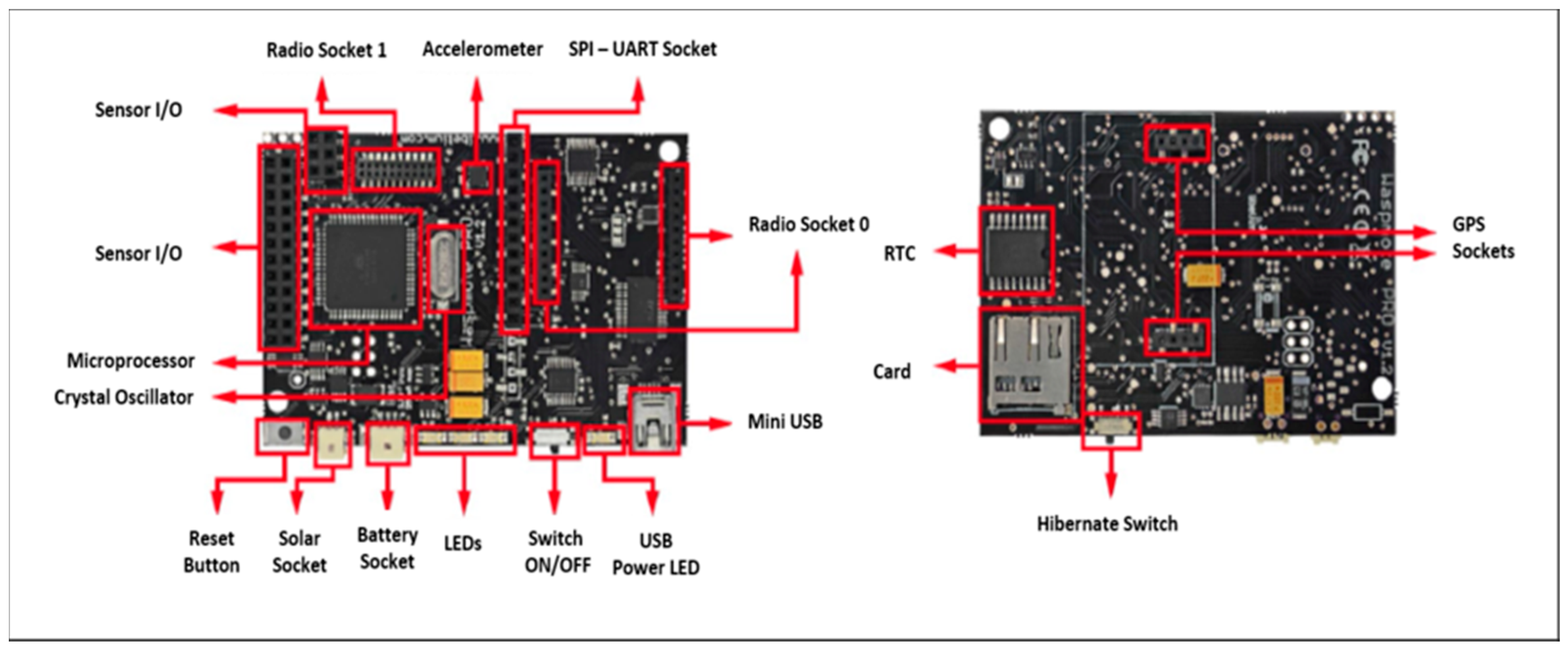
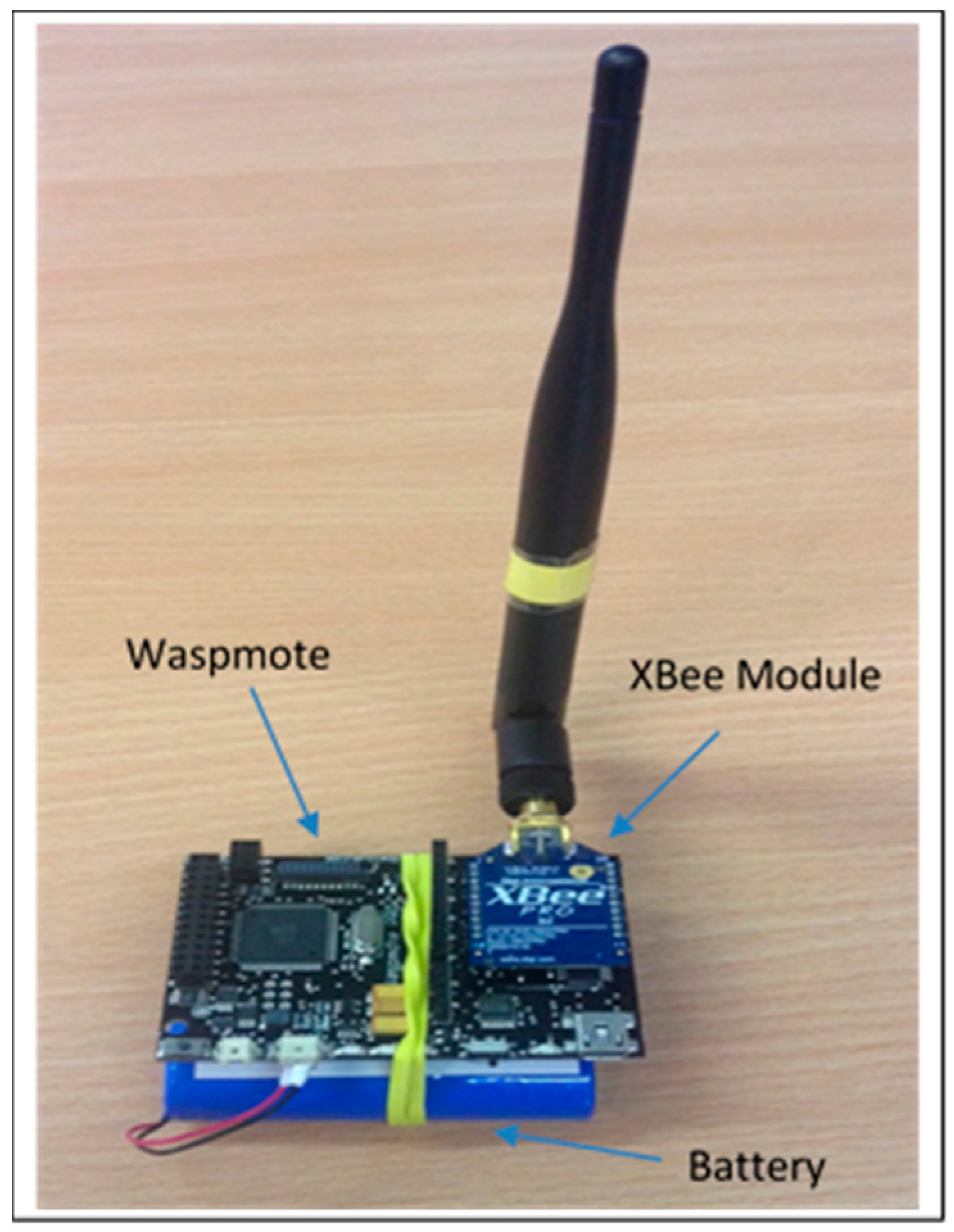
3.2. The Platform
3.3. Travelling Packets
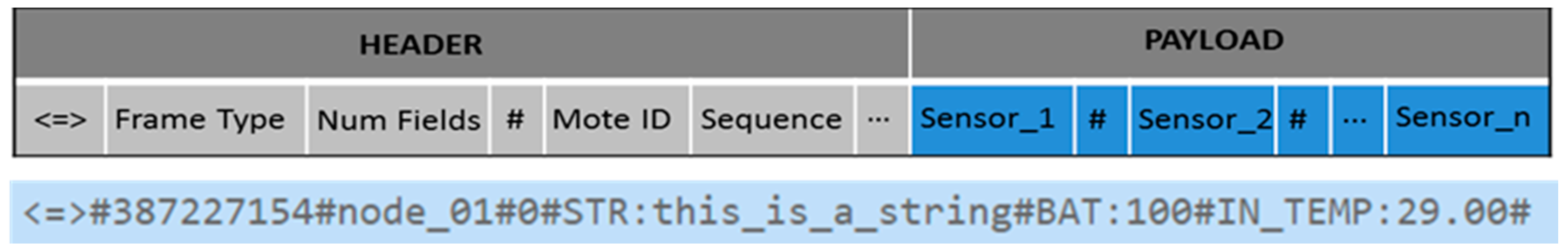
3.4. Packet Structure
- Encryption
- Type of XBee module used
- Transmission mode
3.5. Security and Key Management
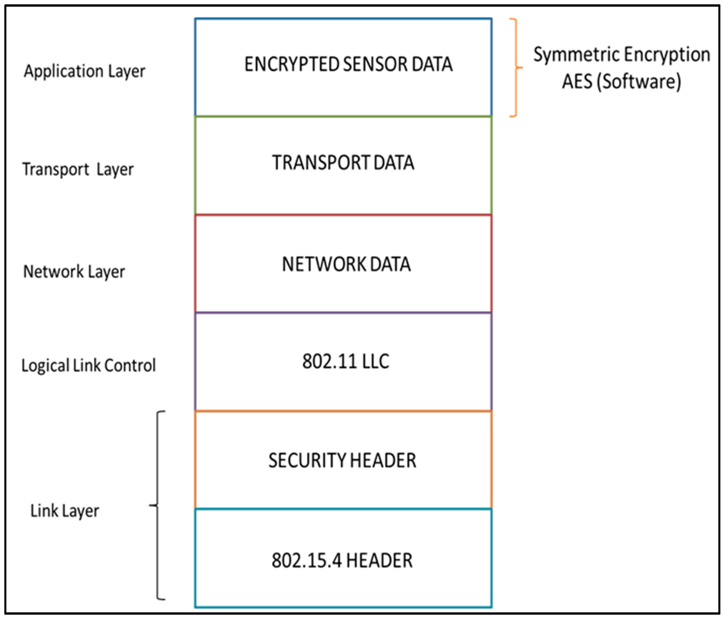
3.5.1. Transmission Security and Data Encryption
3.5.2. Key Pre-Distribution
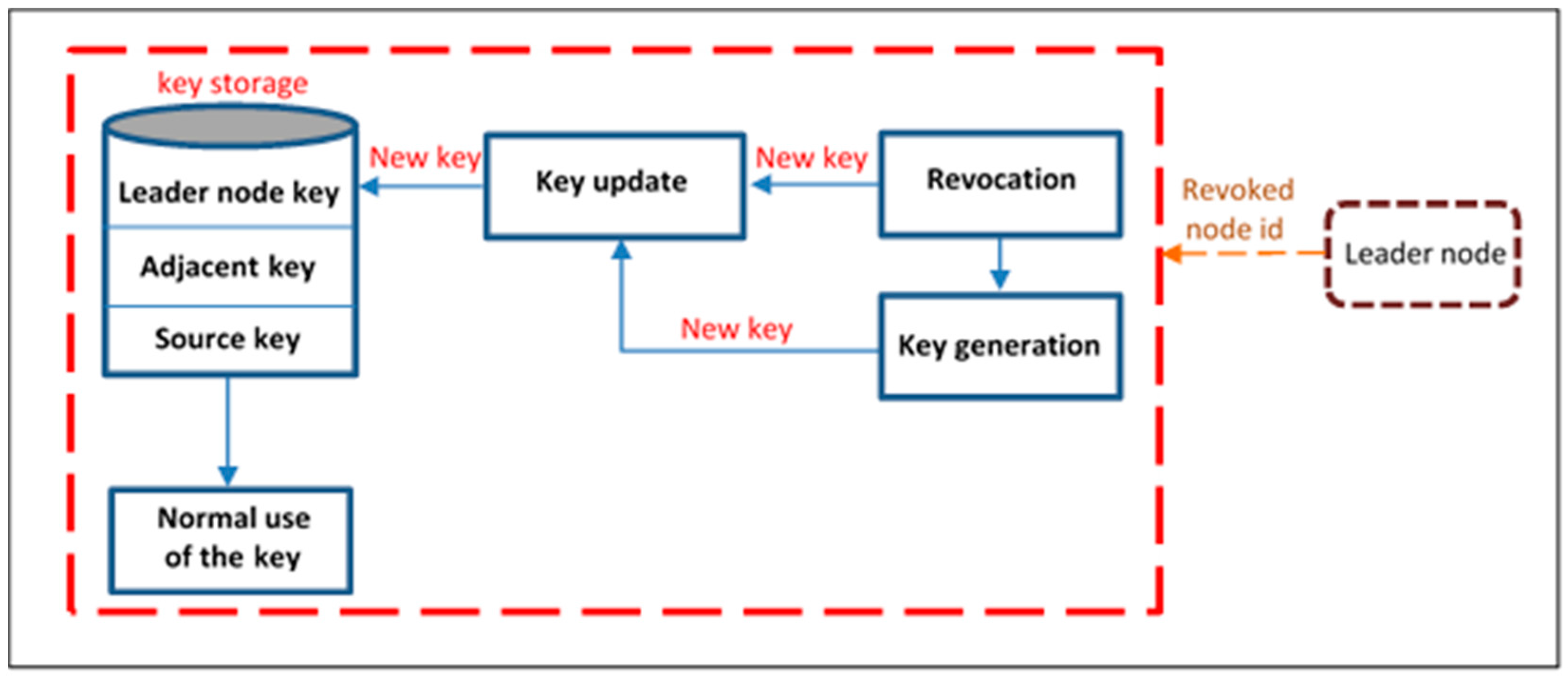
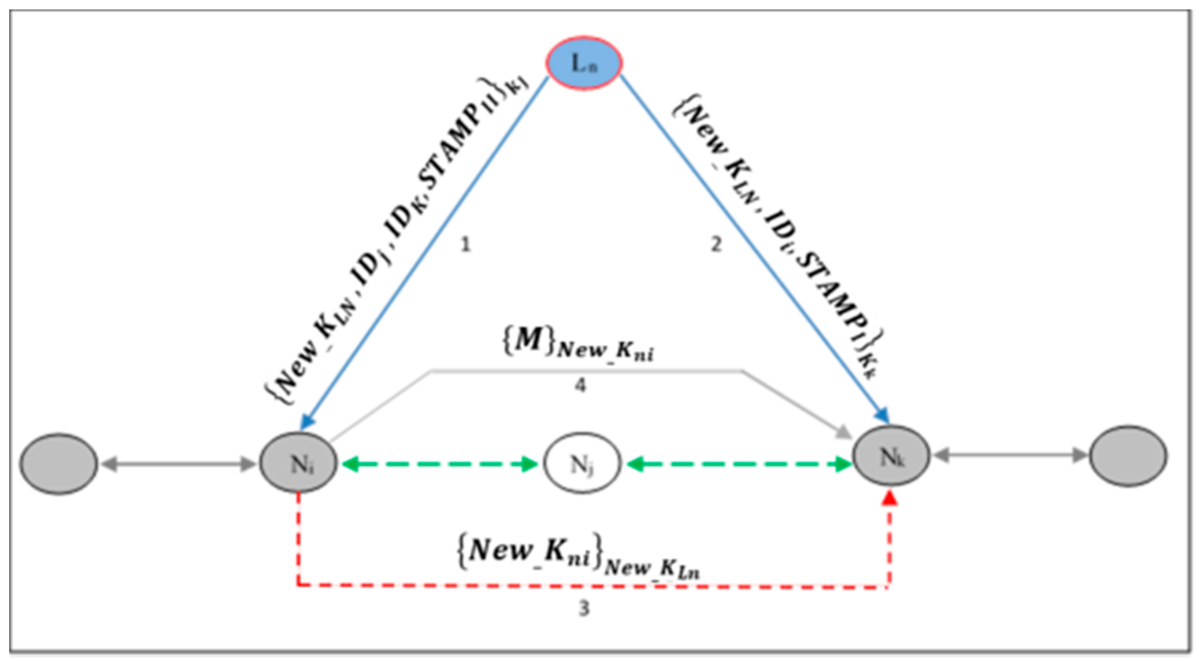
3.5.3. Re-Keying
3.5.4. Memory Requirement
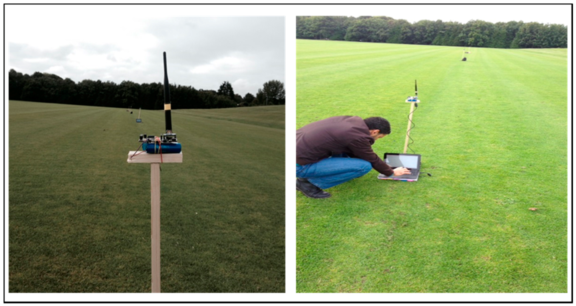
4. Practical Implementation of Proposed Framework
- (1)
- Four nodes and the gateway at a distance of 80, 120 or 160 m between end points in line topology.
- (2)
- Three nodes and the gateway at a distance of 80, 120 or 160 m between end points in the line topology.
- (3)
- One repeater node between sender and the gateway at a distance of 80, 120 or 160 m between end points in the line topology.
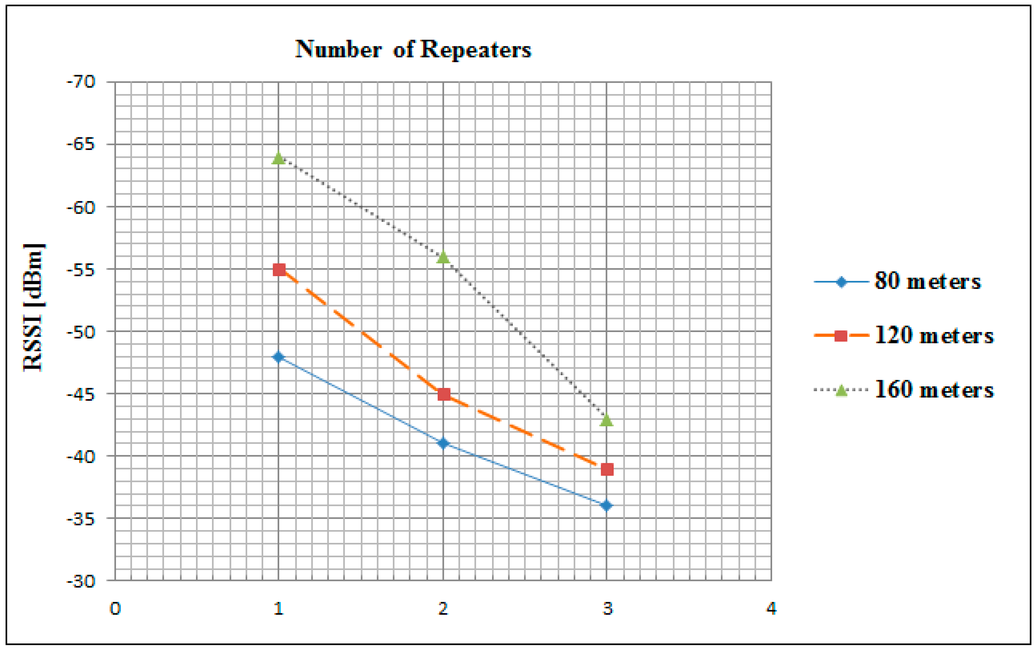
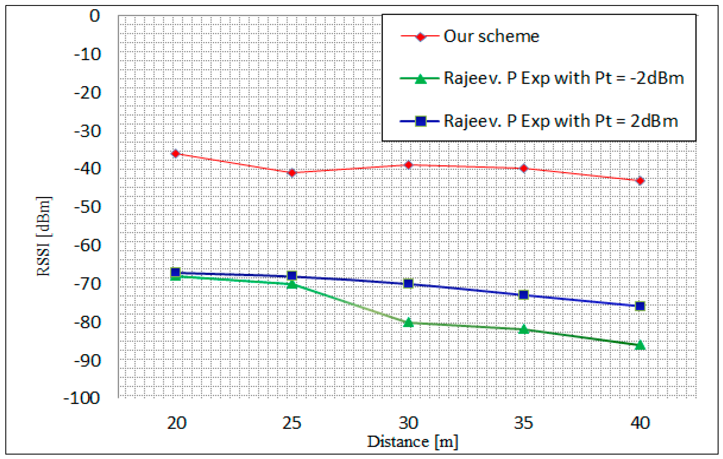
4.1. Received Single Strength Indicator Measurement
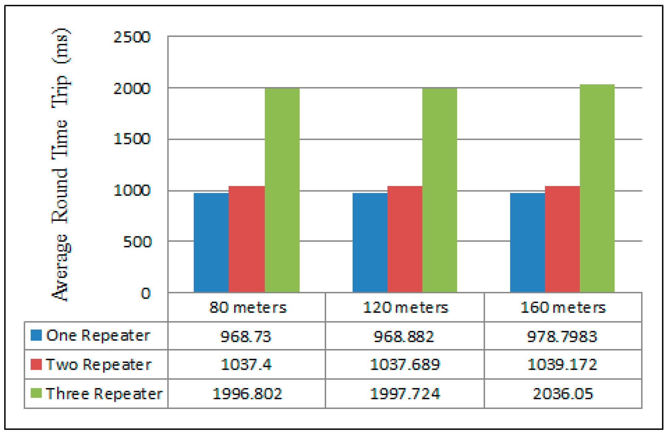
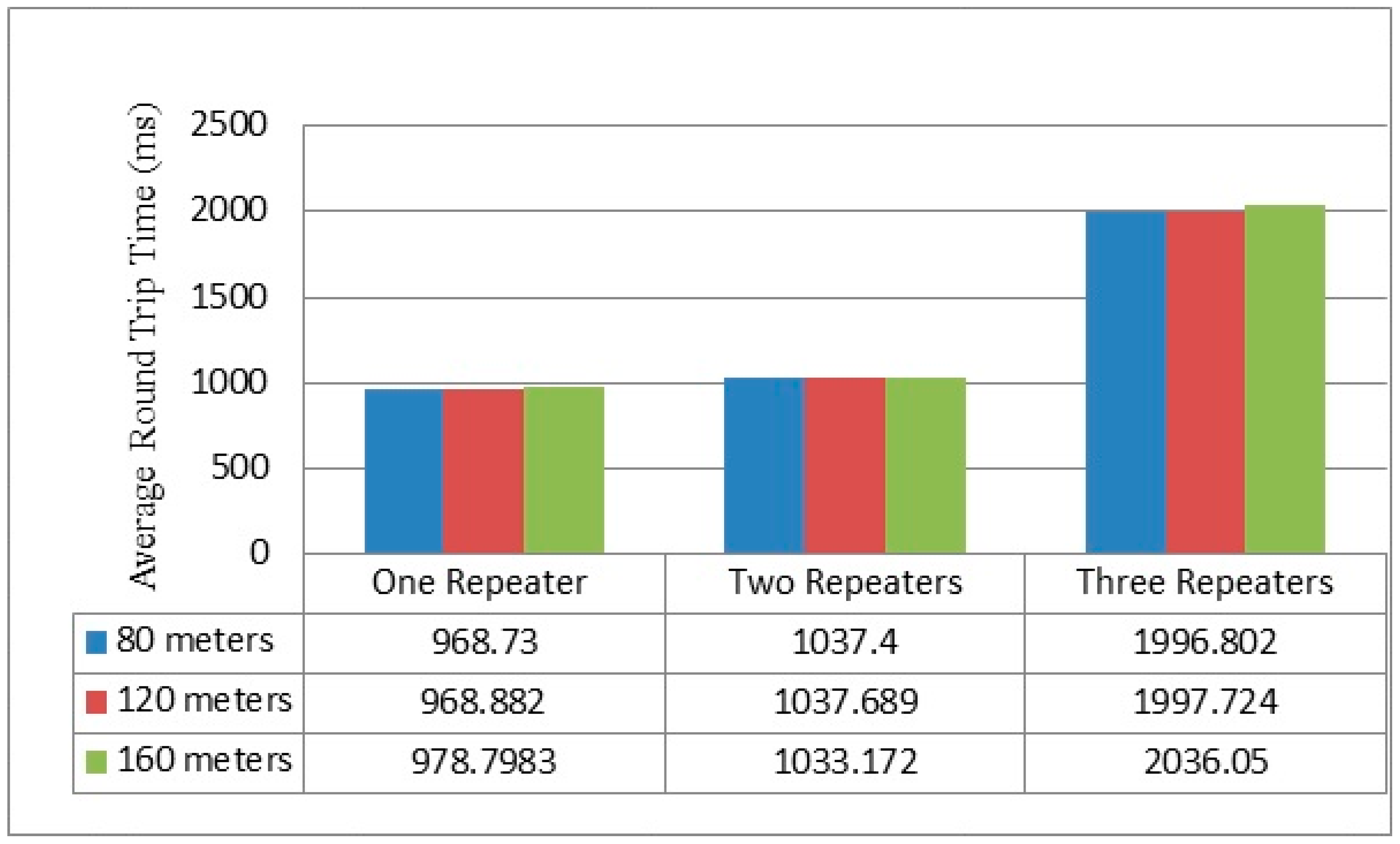
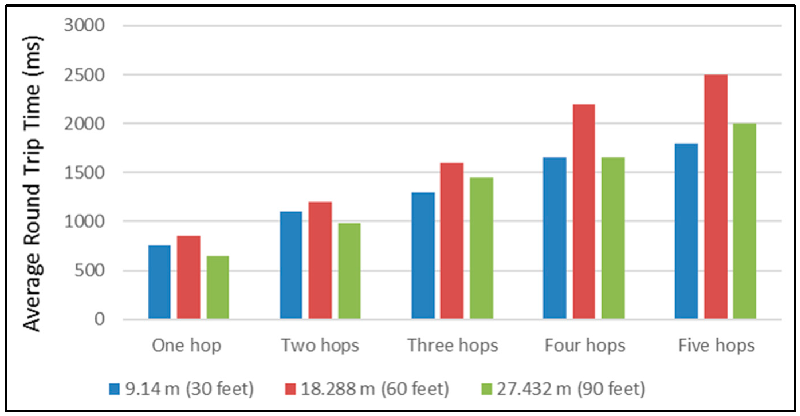
4.2. Round Time Trip Measurement
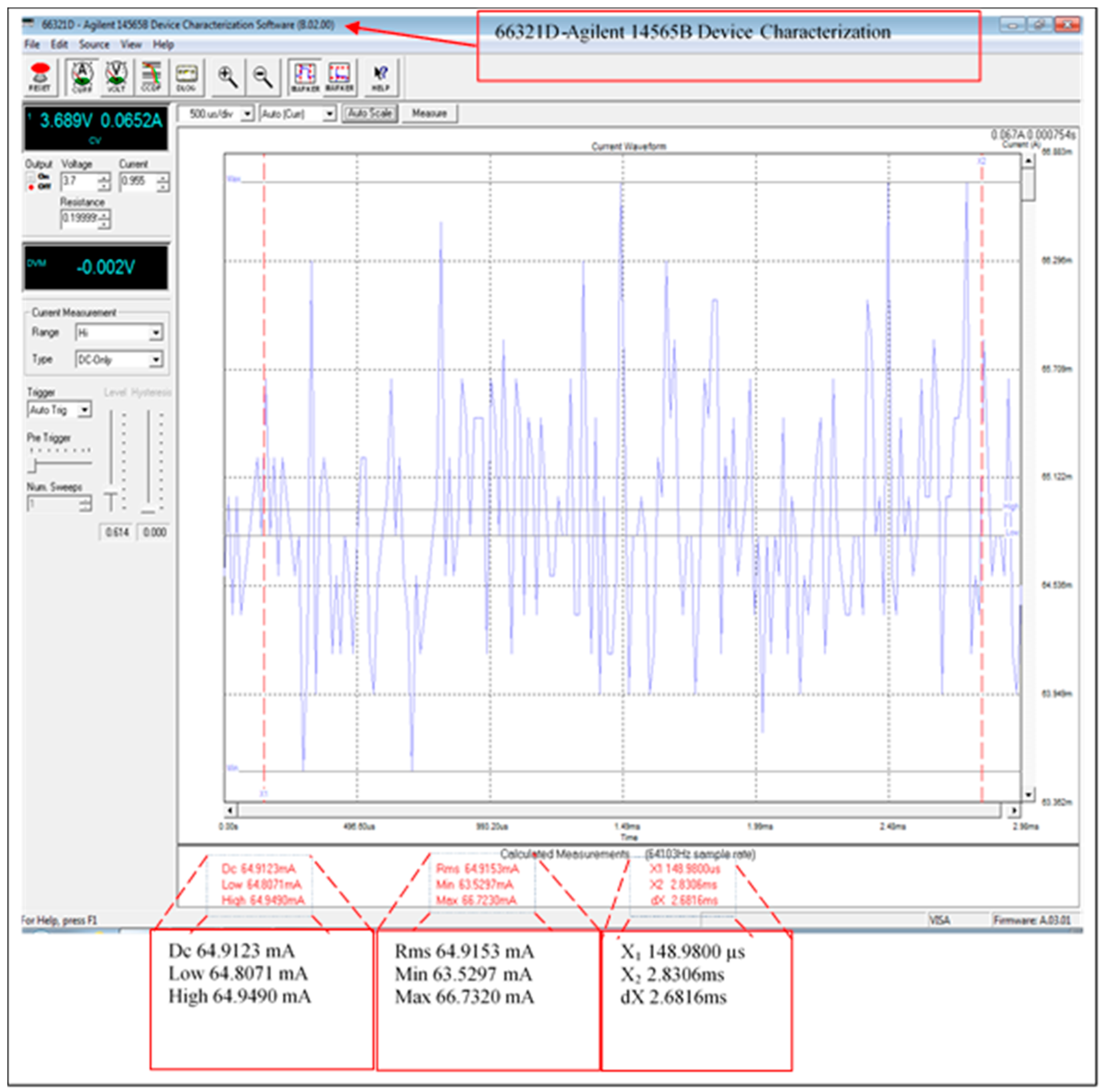
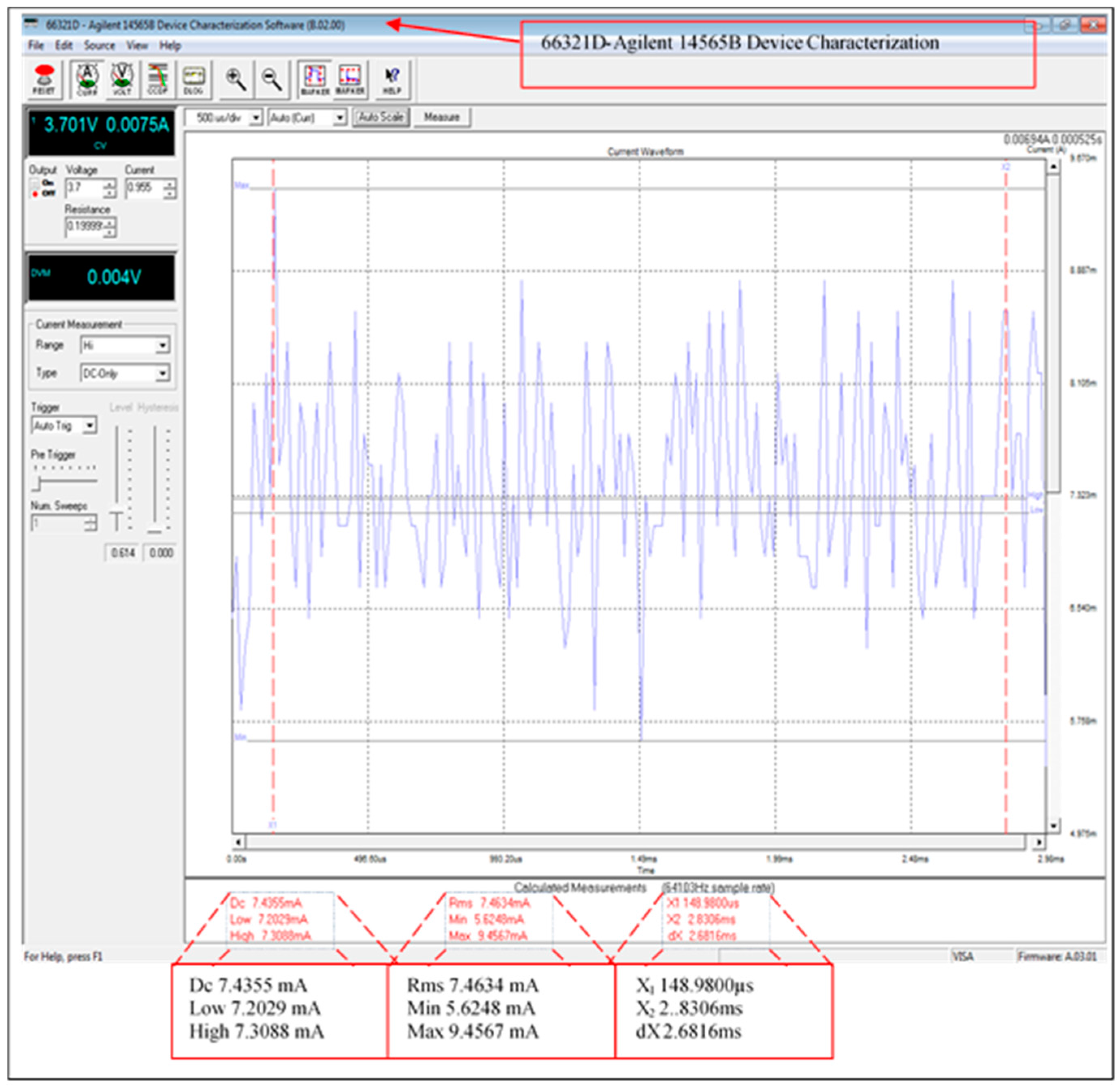
4.3. Current Consumption
5. Discussion and Comparisons
6. Conclusions
- Efficiency: 88.55% of current consumption was reduced using the XBee sleeping mode. This will improve the lifetime of all network sensor nodes.
- Data confidentiality: by doubling the encryption of the messages, we ensure that only the gateway in the network can decrypt the original data (using AES 128) and after that, we establish Peer-to-Peer encryption between repeaters.
- Authentication: each node has an individual key shared with the leader node, which is used to ‘sign’ the messages in order to ensure the authenticity of the new neighbor and the rekeying. This signing is performed when the leader node reconfigures the network topology in the case of joining or revoking network members.
- Memory capacity storage: by using the re-generation function, there is no need for each node to store as many keys as are required in some key pre-distribution schemes where a large pool of keys is located in each node before deployment [20]. In our scheme, each node has only four keys. Therefore, every node requires only a small amount of memory for key storage, which is four times 128 bits.
- Non-repudiation: by signing the XBee acknowledgment messages, there is now verifiable proof that the information sent has really been received by a specific sensor node. This signing using a shared source/destination key, Ks, provides weak non-repudiation as a public key scheme is not yet available in our system.
- Forward security: in the reconfiguration of the scheme, new neighbors could not communicate directly before authentication process. The authentication process coordinates via a leader node.
- Backward security: when a node is revoked from the network, the system ensures that the node cannot receive any new data from the network.
Acknowledgments
Author Contributions
Conflicts of Interest
References
- Mathur, A.; Newe, T.; Rao, M. Healthcare WSN: Cluster Elections and Selective Forwarding Defense. In Proceedings of the 9th IEEE International Conference on Next Generation Mobile Applications, Services and Technologies, Cambridge, UK, 9–11 September 2015; pp. 341–346.
- Elgenaidi, W.; Newe, T. Marine based Wireless Sensor Networks: Challenges and Requirements. In Proceedings of the 8th International Conference on Sensing Technology (ICST), Liverpool, UK, 1–4 September 2014.
- Gura, N.; Patel, A.; Wander, A.; Eberleand, H.; Shantz, S.C. Comparing Elliptic Curve Cryptography and RSA on 8-bit CPUs. In Proceedings of the Cryptographic Hardware and Embedded Systems (CHES), Cambridge, MA, USA, 11–13 August 2004; pp. 119–132.
- Perrig, A.; Szewczyk, R.; Wen, V.; Culler, D.; Tygar, J.D. SPINS: Security Protocols for Sensor Networks. Wirel. Netw. 2002, 8, 521–534. [Google Scholar] [CrossRef]
- Eschenauer, L.; Gligor, V. A key management scheme for distributed sensor networks. In Proceedings of the ACM Conference on Computer and Communication Security (CCS), Washington, DC, USA, 18–22 November 2002; pp. 41–47.
- Chan, A.P.H.; Song, D. Random key per-distribution schemes for sensor networks. In Proceedings of the 2003 Symposium on Security and Privacy, Berkeley, CA, USA, 11–14 May 2003; pp. 42–51.
- Kabara, J.; Calle, M. MAC Protocols Used by Wireless Sensor Networks and a General Method of Performance Evaluation. Int. J. Distrib. Sens. Netw. 2012, 2012, 834784. [Google Scholar] [CrossRef]
- Cuomo, F.; Della Luna, S.; Monaco, U.; Melodia, F. Routing in ZigBee: Benefits from Exploiting the IEEE 802.15.4 Association Tree. In Proceedings of the 2007 IEEE International Conference on Communications, Glasgow, UK, 24–28 June 2007; pp. 3271–3276.
- Wheeler, A. Commercial Applications of Wireless Sensor Networks Using ZigBee. IEEE Commun. Mag. 2007, 45, 70–77. [Google Scholar] [CrossRef]
- Raazi, S.M.K.R.; Lee, S. A survey on key management strategies for different applications of wireless sensor networks. J. Comput. Sci. Eng. 2010, 4, 23–51. [Google Scholar] [CrossRef]
- Liu, A.; Dong, M.; Ota, K.; Long, J. PHACK: An Efficient Scheme for Selective Forwarding Attack Detecting in WSNs. Sensors 2015, 15, 30942–30963. [Google Scholar] [CrossRef] [PubMed]
- Liebeherr, J.; Dong, G. An overlay approach to data security in ad-hoc networks. Ad Hoc Netw. 2006, 5, 1055–1072. [Google Scholar] [CrossRef]
- Wang, V.; Fang, S. A hierarchical key management scheme for secure group communications in mobile ad hoc networks. J. Syst. Softw. 2007, 80, 1667–1677. [Google Scholar] [CrossRef]
- Annadurai, P. Trust Based Hierarchical Key Management Scheme for Secure Group Communication in mobile Ad hoc networks. Int. J. Comput. Sci. Appl. 2008, 1, 974–1003. [Google Scholar]
- Jang, J.; Kwon, T.; Song, J. A Time-Based Key Management Protocol for Wireless Sensor Networks. In Information Security Practice and Experience; Springer: Heidelberg, Germany, 2007. [Google Scholar]
- Zhang, R.; Zhao, H.; Labrador, M.A. A Scalable and Energy Efficient Sink Location Service for Large-scale Wireless Sensor Networks. Ad Hoc Sens. Wirel. Netw. 2007, 4, 289–320. [Google Scholar]
- Luo, H.; Ye, F.; Cheng, J.; Lu, S.; Zhang, L. TTDD: A Two-tier Data Dissemination Model for Large-Scale Wireless Sensor Networks. J. Wirel. Sens. Netw. 2005, 11, 161–175. [Google Scholar] [CrossRef]
- Luomal, J.; Hakala, I. Effective of Temperature and Humidity on radio Signal strength in outdoor Wireless Sensor Network. In Proceedings of the Federated Conference on Computer Sceince and Information Systems, Lodz, Poland, 13–16 September 2015; pp. 1257–1265.
- Rajeev, P.; Seong, L. Performance Analysis of XBee ZB Module Based Wireless Sensor Networks. Int. J. Sci. Eng. 2013, 4, 1615–1621. [Google Scholar]
- Möller, S.; Newe, T.; Lochmann, S. Evaluation of Key Distribution Protocols for use with Wireless Sensor Networks. In Proceedings of the IEEE Sensors Applications Symposium (IEEE SAS 2009), New Orleans, LA, USA, 17–19 February 2009; pp. 25–28.
- Boyle, D.E.; Newe, T. On the implementation and evaluation of an elliptic curve based cryptosystem for Java enabled Wireless Sensor Networks. Sens. Actuators A Phys. 2009, 156, 394–405. [Google Scholar] [CrossRef]
- Cionca, V.; Newe, T.; Dãdârlat, V. Configuration Tool for a Wireless Sensor Network Integrated Security Framework. J. Net. Syst. Manag. 2012, 20, 417–452. [Google Scholar] [CrossRef]
- Möller, S.; Newe, T.; Lochmann, S. Prototype of a secure wireless patient monitoring system for the medical community. Sens. Actuators A Phys. 2012, 173, 55–65. [Google Scholar] [CrossRef]
- Healy, M.; Newe, T.; Lewis, E. Security for Wireless Sensor Networks: A Review. In Proceedings of the IEEE Sensors Applications Symposium (IEEE SAS 2009), New Orleans, LA, USA, 17–19 February 2009; pp. 80–85.


| Symbol | Description |
|---|---|
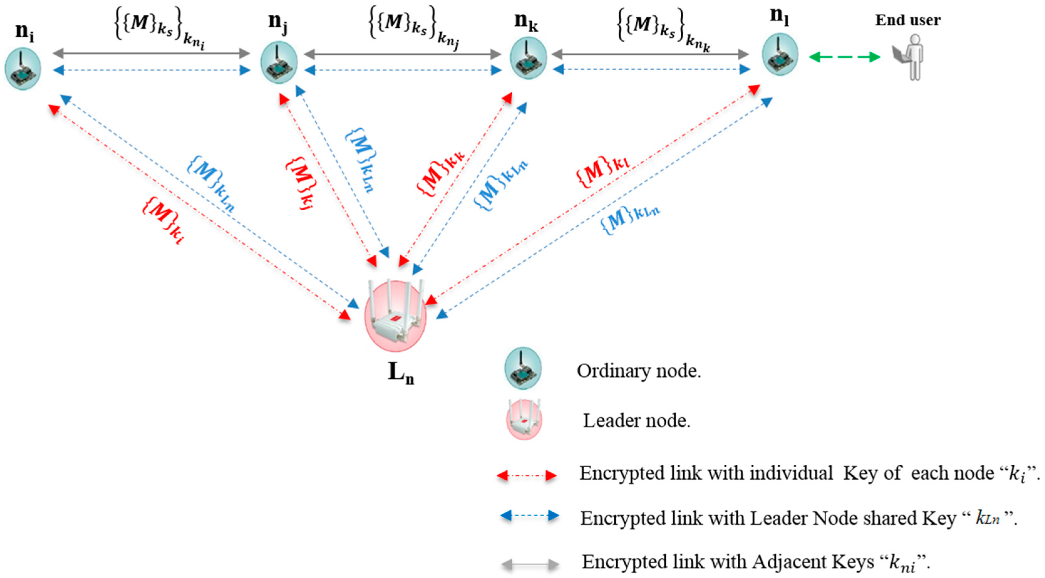
| ni, nj, nk, nl | Ordinary nodes in the line topology |
| Ln | Leader node |
| { }k | Symmetric encryption/decryption with key k |
| M | Transmitted sensor data |
| ks | Secret encryption source key |
| kni | Secret encryption adjacent key of node i |
| ki | Secret encryption individual key of node i |
| kLn | Secret encryption leader node key |
| {{M}ks}kni | Sensor data encrypted with source and adjacent keys |
| {M}ki | Message encrypted with individual key of node i |
| {M}kLn | Message encrypted with leader nod key |
| Module | Protocol | Frequency | Tx_Power | Sensitivity | Range |
|---|---|---|---|---|---|
| Xbee 802.14.5-pro | 802.14.5 | 2.4 GHz | 100 mW | −100 dBm | 7000 m |
| XBee ZBee-Pro | ZBee-Pro | 2.4 GHz | 50 mW | −102 dBm | 7000 m |
| XBee 868 | RF | 868 HMz | 315 mW | −112 dBm | 12 km |
| XBee 900 | RF | 900 MHz | 50 mW | −100 dBm | 10 km |
| WiFi | 802.11b/g | 2.4 GHz | 0–12 dBm | −83 dBm | 7000 m |
| GPRS | - | 8500/900/1800/1900 MHz | 2W(Class 4) 859/900 MHz 1W(Class 1) 1800/1900 Mhz | −109 dBm | km typical carrier range |
| 3G/GPRS | - | Tri-Band UMS 2100/1900/900 MHz Quad-based GSM/EDGE, 850/900/1800/1900 MHz | −106 dBm | km typical carrier range | |
| Bluetooth Low Energy | Bluetooth v.4.0/Bluetooth Smart | 2.4 GHz | −103 dBm | 100 m |
| Module | Maximum Frame Size | ||
|---|---|---|---|
| XBee-802.15.4 | Link Encrypted | @16bit Unicast | 98 Bytes |
| @64bit Unicast | 94 Bytes | ||
| Broadcast | 95 Bytes | ||
| Link Unencrypted | 100 Bytes | ||
| XBee-868 | 100 Bytes | ||
| XBee-900 | Link Encrypted | 80 Bytes | |
| Link Unencrypted | 100 Bytes | ||
| XBee-Digimesh | 73 Bytes | ||
| XBee-ZigBee | Link Encrypted | @64bit Unicast | 66 Bytes |
| Broadcast | 84 Bytes | ||
| Link Unencrypted | @64bit Unicast | 74 Bytes | |
| Broadcast | 92 Bytes | ||
| Bluetooth-transparent connection | Limited by MAX_FRAME | ||
| GPRS | Limited by MAX_FRAME | ||
| 3G | Limited by MAX_FRAME | ||
| LoRa/SX1272 | Limited by MAX_FRAME | ||
| WiFi | Limited by MAX_FRAME | ||
| Algorithm | Key Size | Data Block Size | Mode Cipher | Padding |
|---|---|---|---|---|
| AES-128 | 128 bits | 16 Bytes | ECB | ZEROS |
| Algorithm | Output Size (Bits) | Internal State Size (Bits) | Block Size (Bits) | Max Message Size (Bits) | Word Size (Bit) |
|---|---|---|---|---|---|
| MD5 | 128 | 128 | 512 | 264 − 1 | 32 |
| Scheme Mode | Measured Current Consumption (mA) | ||
|---|---|---|---|
| Max | Min | Average | |
| Fully functional system | 66.732 | 63.5297 | 64.9123 |
| XBee module (sleeping) | 9.4567 | 5.6248 | 7.4355 |
| XBee module current consumption (awake) | 57.2753 | 57.9049 | 57.4768 |
| Scheme | Offline Phase | Cryptographic Scheme | Key Size (bits) | Communication Type | Number of Storage Keys | Memory Space Used by the Scheme | Re-Keying Strategy |
|---|---|---|---|---|---|---|---|
| Neighborhood Scheme [12] | Certificate stored in each node | Hybrid (RSA and symmetric) | 128 | Multicast/Unicast | Each node stores: own public/private keys; own secret neighborhood key; neighbors secret key(s), and source key (used when the node is data source) | Not Given | Local operation, where each node updates keys with its current neighbor. |
| Hierarchical Key Management Scheme [13] | No pre-loaded keys | Hybrid (D–H and Symmetric) | Not Given | Broadcast (2-hop adjacent node) |
| Not Given | Complicated operation where each level head node must regenerate a number of keys. |
| Time-Based Key Management Scheme [15] | Keys pre-loaded | Symmetric | 64 | Broadcast |
|
| Only the nodes deployed at the same time when compromised node is revoked have to regenerate keys. |
| Presented Scheme | Keys pre-loaded | Symmetric AES-128 in ECB mode with zeros padding. Key generation -MD5 and RTC. | 128 | Unicast | (5 keys) Each ordinary node stores; own adjacent key; neighbor shared adjacent key; an individual key that is shared with leader node; Leader node master key, and a source key (used when the node is data source). | Program size 57,230 bytes Ram required 4987 bytes. | Re-keying in this scheme is a local operation, where only one node must update its adjacent key, in addition to the leader node key. |
| Scheme | Implementation Environment | Node Coordination | Comments |
|---|---|---|---|
| Neighborhood Scheme [12] |
|
|
|
| Hierarchical Key Management Scheme [13] | Simulation only |
|
|
| Time-Based Key Management Scheme [15] | Simulation only |
|
|
| Presented Scheme |
|
|
|
© 2016 by the authors; licensee MDPI, Basel, Switzerland. This article is an open access article distributed under the terms and conditions of the Creative Commons Attribution (CC-BY) license (http://creativecommons.org/licenses/by/4.0/).
Share and Cite
Elgenaidi, W.; Newe, T.; O’Connell, E.; Toal, D.; Dooly, G. Secure and Efficient Key Coordination Algorithm for Line Topology Network Maintenance for Use in Maritime Wireless Sensor Networks. Sensors 2016, 16, 2204. https://doi.org/10.3390/s16122204
Elgenaidi W, Newe T, O’Connell E, Toal D, Dooly G. Secure and Efficient Key Coordination Algorithm for Line Topology Network Maintenance for Use in Maritime Wireless Sensor Networks. Sensors. 2016; 16(12):2204. https://doi.org/10.3390/s16122204
Chicago/Turabian StyleElgenaidi, Walid, Thomas Newe, Eoin O’Connell, Daniel Toal, and Gerard Dooly. 2016. "Secure and Efficient Key Coordination Algorithm for Line Topology Network Maintenance for Use in Maritime Wireless Sensor Networks" Sensors 16, no. 12: 2204. https://doi.org/10.3390/s16122204
APA StyleElgenaidi, W., Newe, T., O’Connell, E., Toal, D., & Dooly, G. (2016). Secure and Efficient Key Coordination Algorithm for Line Topology Network Maintenance for Use in Maritime Wireless Sensor Networks. Sensors, 16(12), 2204. https://doi.org/10.3390/s16122204