1. Introduction
Functional mobility usually refers to the skill of ambulating safely in a free living environment by walking, running, climbing and even when handling assistive devices, such as walkers, crutches and canes [
1,
2]. About 15% of the world’s population live with some disability condition, of which 2%–4% suffer significant functional problems [
3]. In this scenario, one of the major goals of neuromuscular rehabilitation is to regain gait function in order to promote more independent lives [
4]. The assessment of functional activities, such as walking, can help clinicians to determine patients’ autonomy level and the optimal care they should receive [
5].
Therefore, it is essential to understand and characterize systematically motion disturbances to improve the diagnosis, enhance treatments and measure patients’ evolution. The estimation of joint angular displacements is a fundamental part of human motion analysis and involves the detection of joint position and spatial orientation [
6]. The relevance of these parameters is observed in many clinical scenarios such as gait training and rehabilitation in patients with stroke, Parkinson’s disease and cerebral palsy [
7,
8,
9].
In contrast to camera-based laboratory systems for measuring joint angles, wearable sensors present advantages of lower cost, higher flexibility, portability and adaptability [
6,
10]. This is the case of inertial measurement units, commonly referred to as IMUs or inertial sensors. These sensors are a multi-axial combination of accelerometers, gyroscopes and eventually magnetometers, which can be attached to different body segments to estimate joint kinematics. Considering their usability in internal and external environments and fast donning and doffing, these sensors represent a promising technology that may become an alternative to high-cost optical systems [
11,
12,
13,
14,
15].
This topic has evolved into a wide and solid field of research, but clinical applications involving the use of IMUs are still largely unexplored in the literature. Perhaps this is due to the lack of standards for placing sensors on body segments and defining joint coordinate systems (JCS), which limits the correct calculation of joint kinematics. Also, some studies have questioned the accuracy of these systems [
16,
17,
18,
19,
20]. Researchers have stated that the calibration stages of the individual sensors (i.e., accelerometer, gyroscope, and magnetometer), biases, sensibilities and different noise types, in addition to sensor fusion algorithm issues, influence the accuracy of the orientation estimation.
Regarding these situations, a fundamental problem of the IMU-based gait analysis is to how define an appropriate measurement protocol and provide a sensor-to-body calibration procedure [
21]. Because IMUs’ local frames are not aligned with anatomically defined frames, different approaches in the literature have presented different methods to determine the sensor frame’s orientation with respect to the body segment frame [
13,
14,
15,
22]. However, those approaches suffer from some limitations. One main problem with algorithms based only on data from accelerometers and gyroscopes [
11,
13,
23,
24] is the difficulty to define a common reference frame and, consequently, measure 3D angles. To accurately measure 3D angles, a second global reference axis is necessary along with the gravity vector. This second reference axis is commonly the magnetic field vector, measured by sensor units that include magnetometers. Since heading drift remains a problem within systems that involve only accelerometers and gyroscopes, the anatomical calibration techniques that use such systems rely on predefined user movements to define the axis of joint motion [
11], or use supplementary devices such as cameras [
24], anatomical landmark pointers [
12] or exoskeleton harnesses [
13]. The need for these additional tools also increases the experiment duration and requires experienced personnel, which may be impractical in daily clinical routine.
Other works are based on performing complex movements while keeping some specific postures [
13,
14,
22], or maintaining the same orientation or joint angle between two postures [
15,
24], which may not be simple tasks if to be performed by subjects with motor disabilities. Even for subjects without disability, performing these tasks requires the assistance of examiners. Hence, these mentioned methods may be more prone to calibration errors.
The objective of this work is to present a novel calibration procedure as a method to align IMU sensors to body segments, which compared to the aforementioned methods, is based on fast and simple sensor placement procedures, with no need for movements performed by the user nor any additional tools. Initially, we propose a validation protocol of the procedure using a simplified rigid-body joint that comprises two semi-spheres. A universal goniometer is used as the gold standard measure in order to ensure controlled angular movements. Additionally, we present an application of the method on five able-bodied subjects performing a gait test. The kinematic data of the lower limb joints is presented descriptively.
This paper is organized as follows:
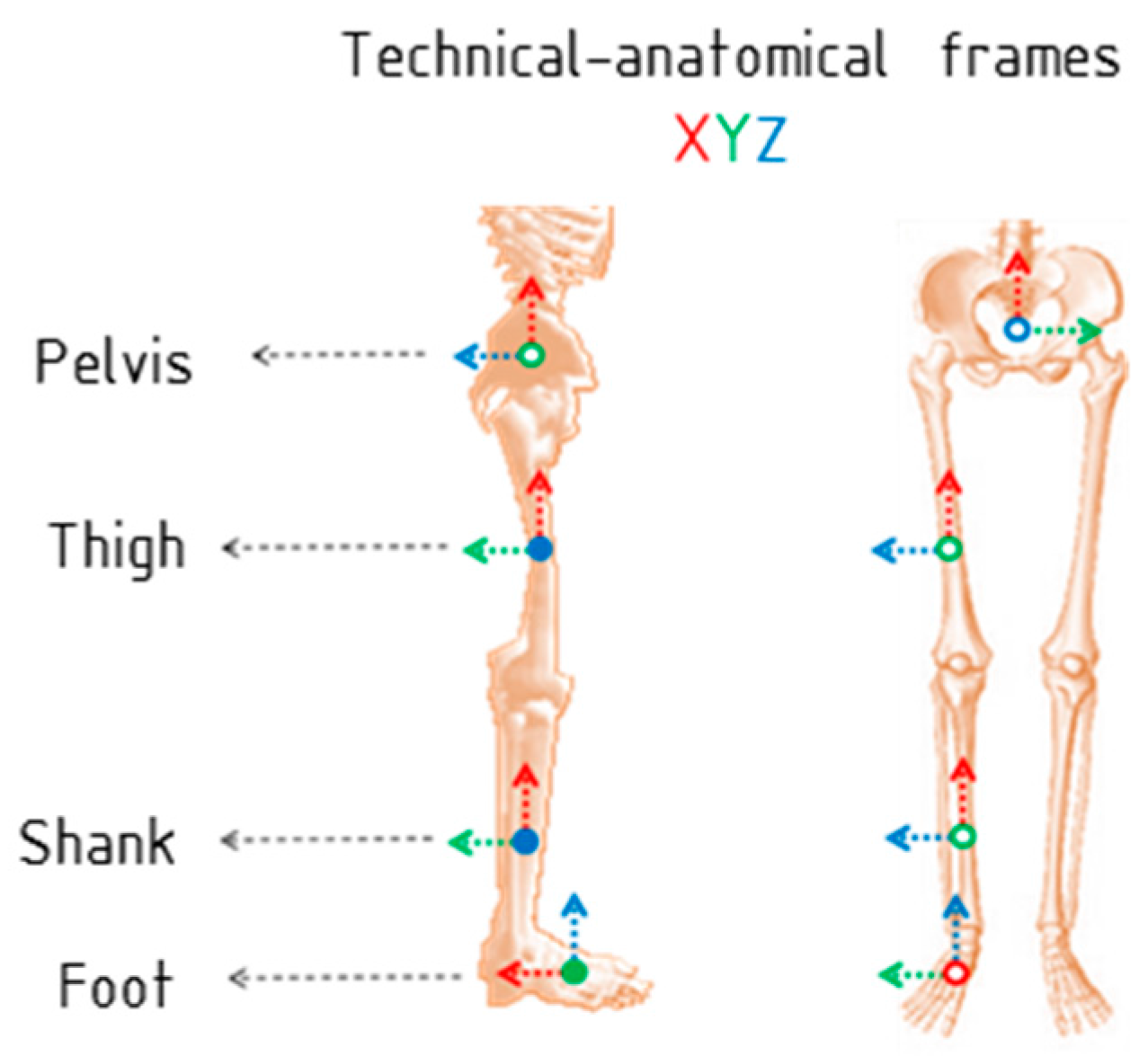
Section 2 describes the proposed IMU-to-body alignment method that includes the calibration algorithm, definition of technical-anatomical frames and calculation of joint angles. Then, in
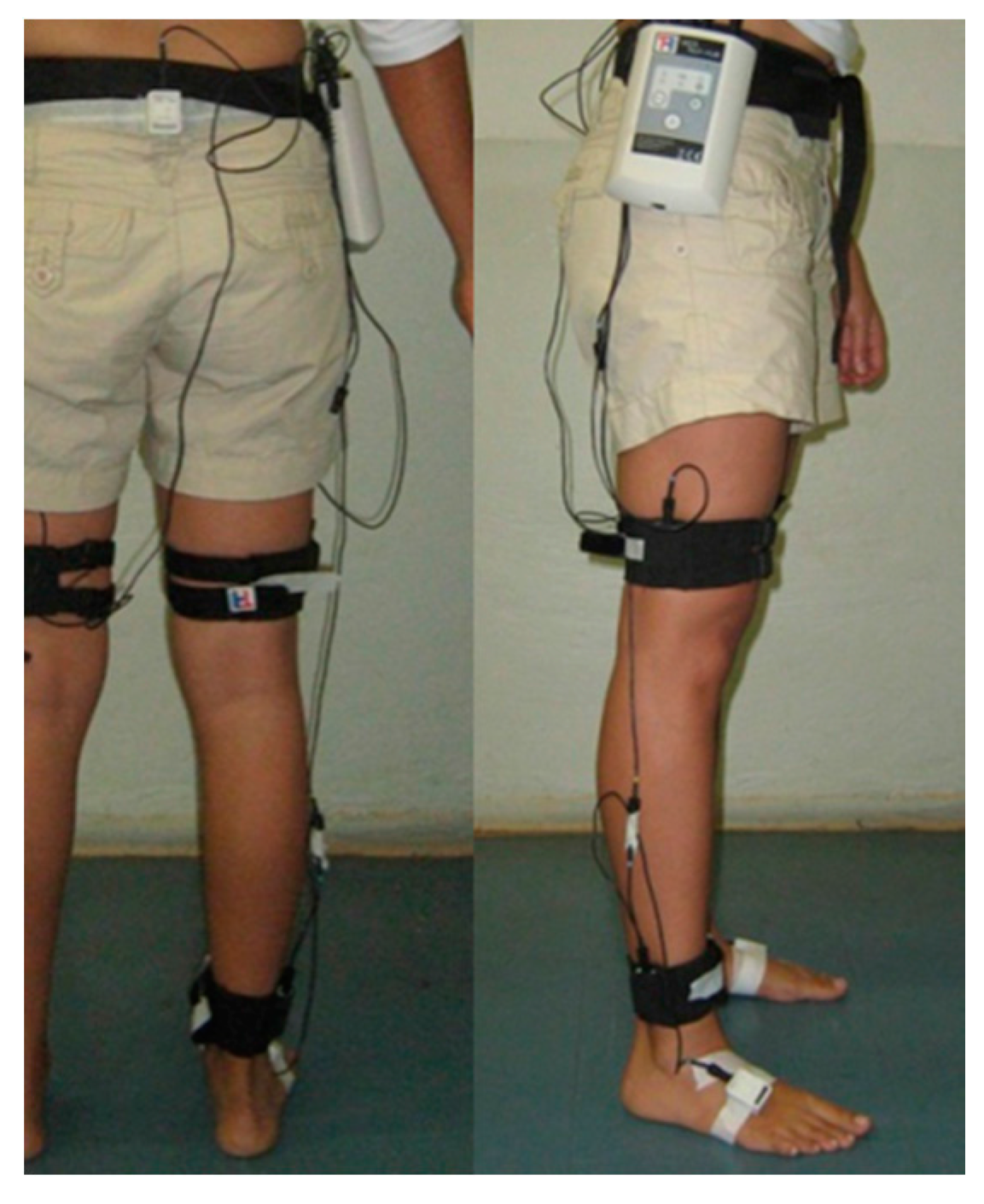
Section 3 we present the motion acquisition system and the validation protocol using the simplified joint, along with an evaluation procedure to quantify the accuracy and repeatability of the technique. Following, a sensor placement protocol and an estimation of kinematic data on subjects without functional disability are introduced in
Section 4. Finally, we provide the results and discussion of the experiments that validate the proposed method (
Section 5), followed by the conclusions (
Section 6).
5. Results and Discussion
This section presents the results of three approaches applying the proposed method: (1) A simulation that evidences the method performance regardless of drift errors and other perturbations associated with the IMU sensors (considering the limitations of the systems and applications that involve IMU sensors [
12,
13,
14,
15,
16,
22,
32]); (2) a practical validation using an experimental simplified rigid-body joint and four IMU sensors; and (3) an application in human gait analysis.
5.1. Simulation of the Proposed Method Applied to a Simplified Rigid-Body Joint
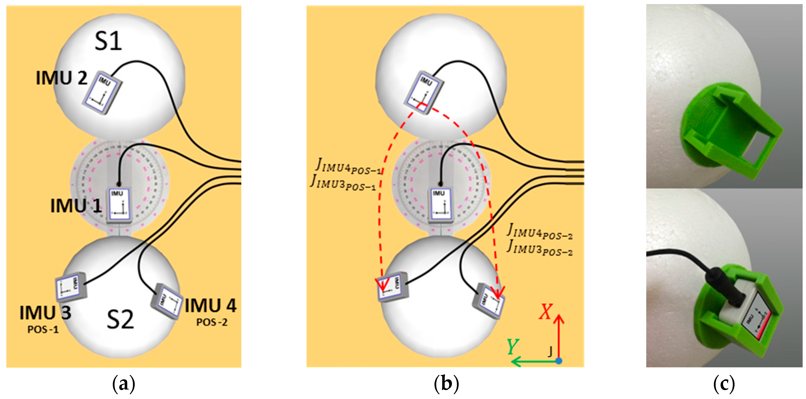
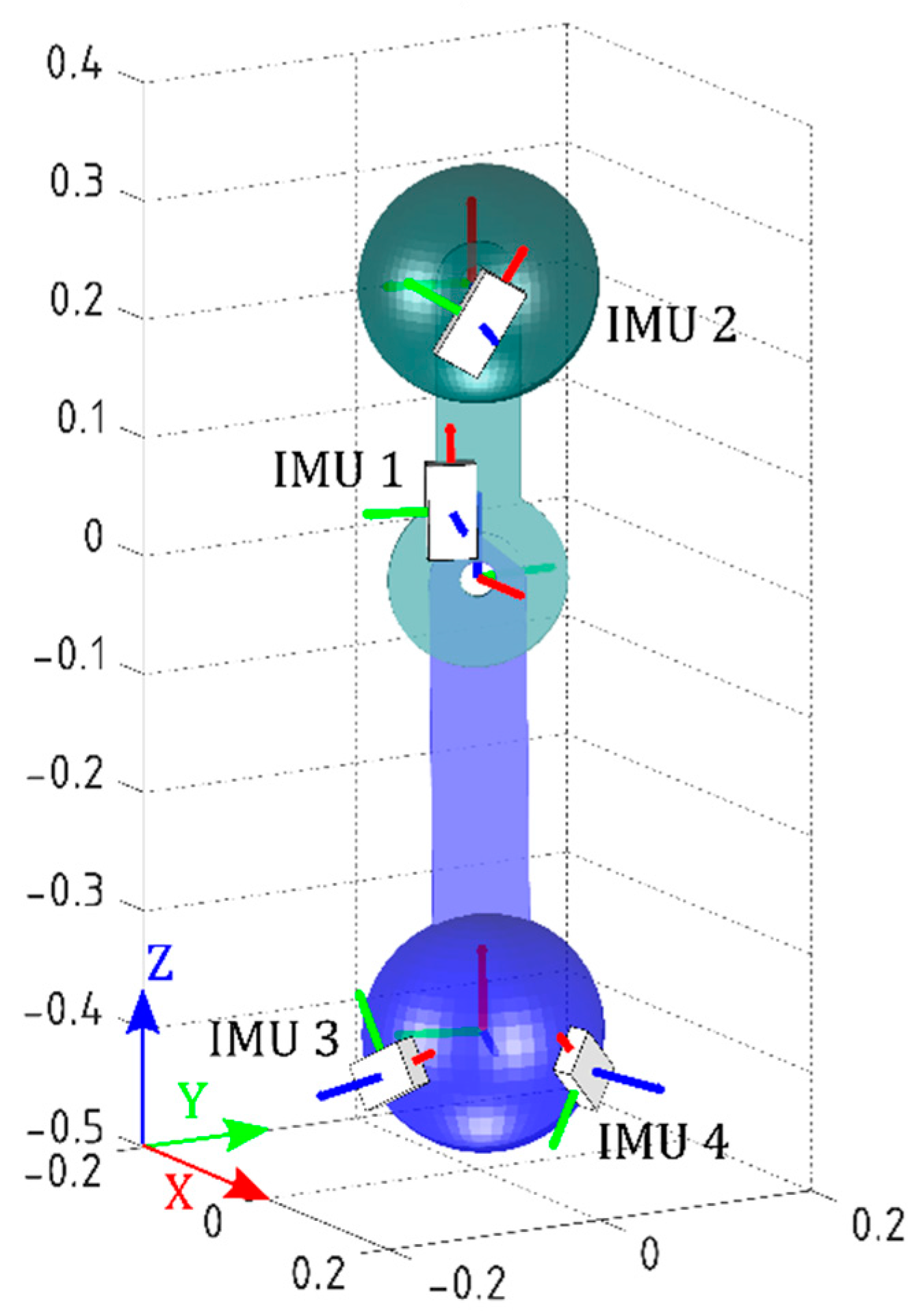
The IMUs’ initial orientations were set to the initial values obtained during practical validation, in order to run the simulation as close as possible to the real experiment. The models of the joint and the IMUs are shown in
Figure 4. Movements from 0° to ±80° with steps of ±20° (called Postures 1 to 9) about
z-axis of J were performed. Note that the simplified joint is analogous to a two-dimensional knee joint with one degree of freedom.
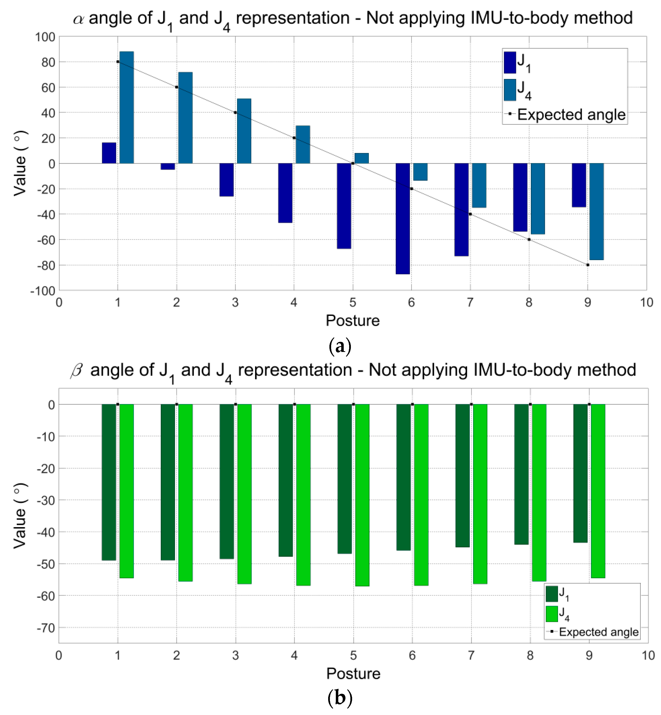
Figure 5a–c show the angular components (
,
and
) of the representations J
1 and J
4 (refer to
Table 5) without applying the proposed method. Other representations of joint J present the same results. Because the proposed method was not yet applied, the angular components
,
and
presented differences with the expected values. The maximum errors can be observed for J
1:
(Posture 5) −67.26°,
(Posture 1) −48.96°,
(Posture 1) 38.77°, and for J
4:
(Posture 2) −11.69°,
(Posture 5) −57.09°,
(Posture 9) −42.15.
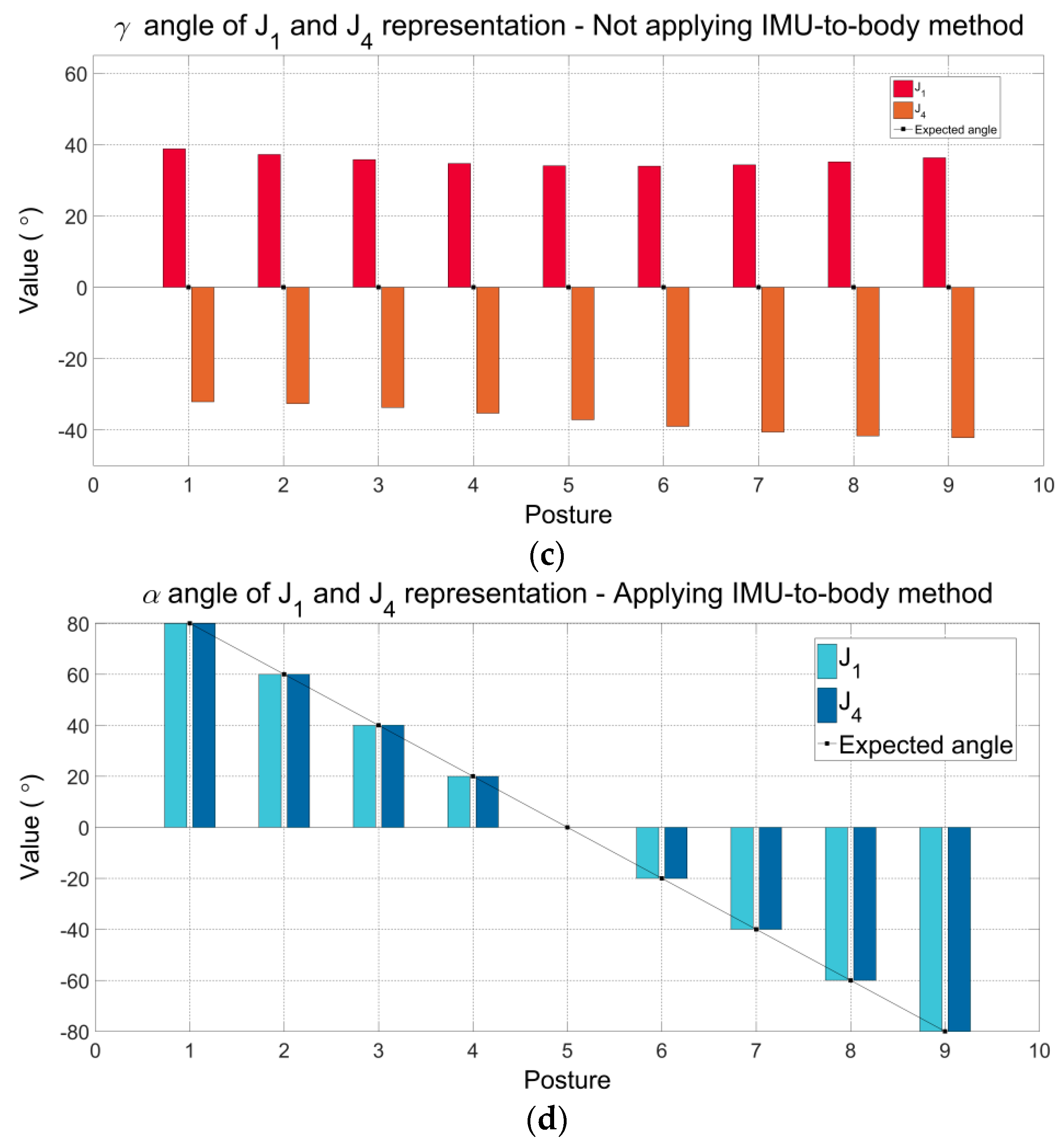
After applying the proposed method, only
is significant under ideal conditions understanding that the rotations were applied exclusively around
z-axis. Then, angular components
and
γ are equal to zero. The angles
obtained by applying the IMU-to-body method are shown in
Figure 5d. Notice that, as the angles
and
are equal to zero, they are not graphically presented. Also, please observe that the values of
α for J
1 and J
4 are equal to the expected values imposed by the simulation. In summary, through this simulation, we aim to demonstrate that applying the proposed method the estimated angles are equal to the expected values and consistent with the rotations applied. In addition, we also show that the proposed method produces the correct and consistent values when the IMU sensors are placed in different positions on the body segments.
5.2. Practical Validation of the Proposed Method Applied to a Simplified Rigid-Body Joint
Table 7 shows the data from ICC coefficients and its respective confidence intervals (95% IC) to evaluate the consistency of repeated measures of the IMU system under stated condition on two different days. ICC values were greater than 0.90 for all angular components and the different representations of the joint J. Movements associated with angles
, which correspond to flexion-extension angles on sagittal plane, produced the highest ICC values of the joint (ICC = 1.00). Observe that the angular component
presented the lowest ICC values and the confidence intervals were wider (e.g., 0.60–0.97). We believe that such values are caused by limitations of the current IMU technology and fusion algorithms. The movements associated with
γ angles correspond to external-internal rotation angles, which are performed on transversal plane, perpendicular to the gravity vector. In accordance with the literature, these movements around to the gravity vector present heading drift, which cannot be corrected using the accelerometer data. Therefore, this drift error may be associated with the performance of the magnetometer, gyroscope, and data fusion algorithm. Also, it has been mentioned that the heading drift is mainly due to the accuracy of the IMU sensors and, on a lesser extent, to the complexity of the task [
33].
Table 8 and
Table 9 report the Root Mean Square Error (RMSE) and Concordance Correlation Coefficient (CCC) obtained between first-day measured joint angles (using IMU system) and reference values (using the gold-standard universal goniometer) to evaluate validity, respectively.
The agreement between measures from IMU system and the universal goniometer applying the calibration procedure was excellent (CCC ≥ 0.98) for the angular component
α. Note that for this angular component the maximum RMSE was 1.70° for the J
4 representation on posture 2 (60°). Also, observe that the maximum RMSE (15.61°) is in correspondence with the angles
. Again, these error drifts may be associated with the quality of the IMU data. In a previous validation study [
34], the IMU sensors used here presented errors approximately up to 7° across 12 explored orientations, following the self-IMU consistency (SC) test. Errors were found up to 15°, following the Inter-IMU consistency (IC) test. These mentioned tests, with similar results, were proposed by Picerno et al. [
16].
Note that the representations of J associated with IMU 3 (J1 and J2) presented lowest RMSE and highest CCC values broadly. It is possible to observe that for the angular component , the measurements are not significantly different when using IMU 3 or IMU 4. However, for the angular components and , the measurements using IMU 3 are lower than those using IMU 4. Additionally, using IMU 3 (the best case), RMSE values of and apparently have similar magnitudes. Nevertheless, note that the magnitudes are not correlated with the same sense of rotation, it means that, for J1 representation (IMU 3: POS-1), errors are higher from 0 to −80°. On the other hand, for J2 representation (IMU 3: POS-2), errors are higher from 0 to 80°. Contrary to that demonstrated in simulation, the RMSE data suggest that the position of real IMU sensors is an important factor to consider in analyzes that involve the secondary planes of motion (coronal and transverse planes).
Besides, it is worth noting that the RMSE and CCC values mostly decrease as the angle increases. This can be observed for the angular components and of the J2 representation. The angular component presented the lowest CCC values (0.02 ≤ CCC ≤ 0.05), however, note that for punctual cases, the CCC values were presented into acceptable to excellent interval. For example, for J1 representation between 80° to −20° (as highlighted in green color), the CCC values were from 0.48 to 0.99, corresponding with RMSE values smaller than 2.5°. This behavior may indicate that pairs of IMU sensors can be used on specific joints, according to their range of motion in gait analysis and, even in other applications that define limits of motion within the range of acceptable performance of the sensors. According to the results obtained using the simplified joint, we present in the next section the hip, knee and ankle joint angles in the sagittal plane through motion analysis using the proposed method.
5.3. Experimental Validation for Gait Analysis
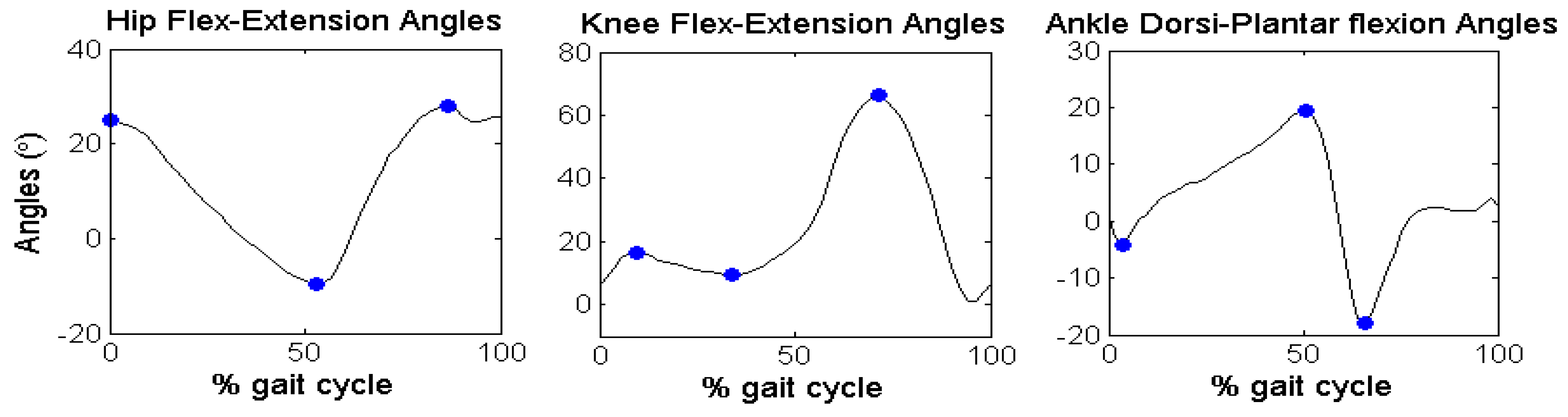
Figure 6 reports the discrete angular parameters (see
Table 6) proposed for gait analysis of Subject 2, as an example, over one cycle of gait, to show graphically the kinematic parameters selected in the angular series.
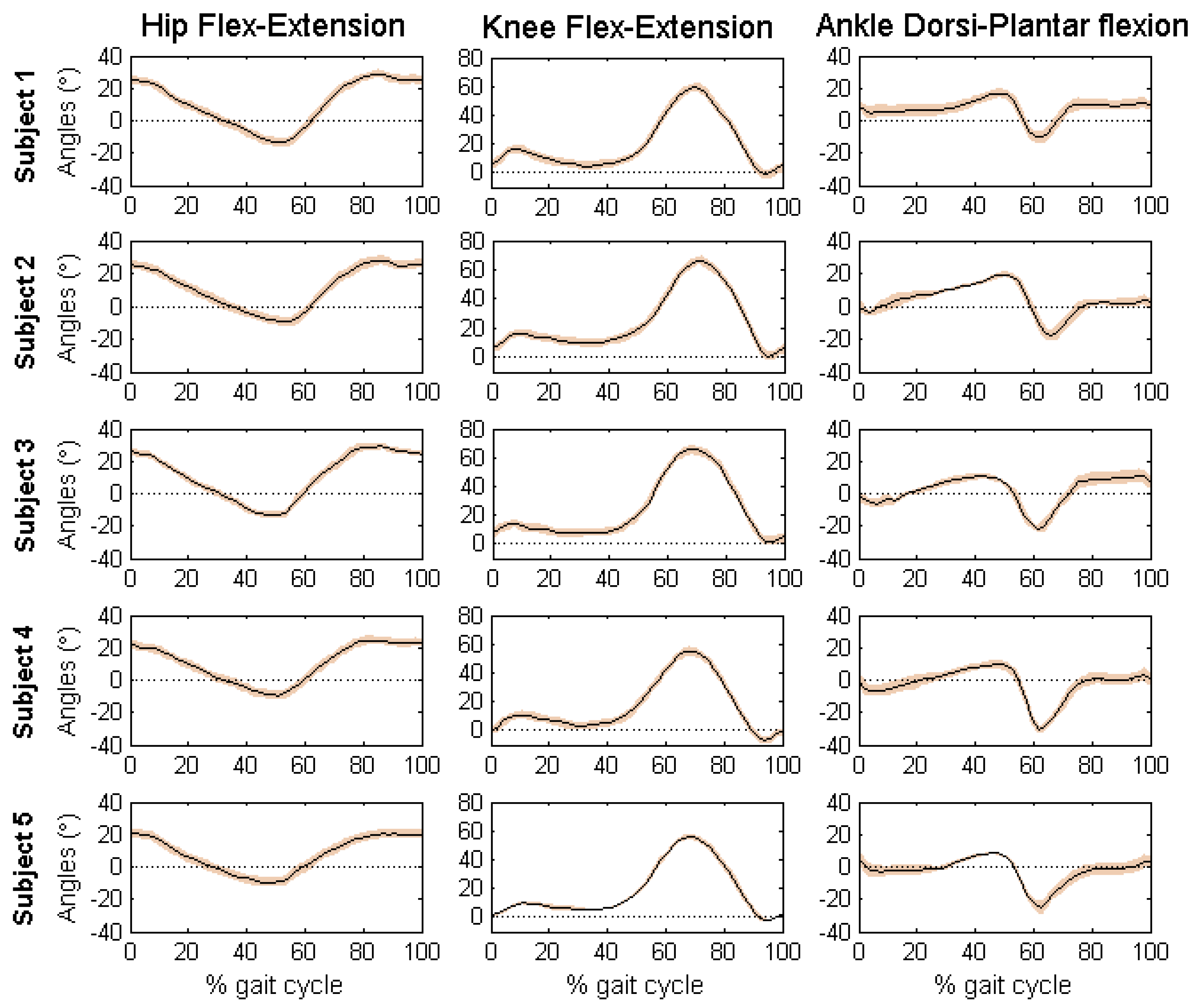
Figure 7 reports the mean and standard deviation of the joint angles in sagittal plane of the five volunteers.
Table 10 shows the discrete angular parameters calculated using the mean of fifteen gait cycles for the five volunteers.
Mean and standard deviation of the joint angles of the five volunteers are within the normal range during a gait cycle for free walking. Interestingly, the results obtained with the developed algorithm presented low standard deviations, which means that estimated measures were consistent across trials. The maximum values of standard deviation were presented for the ankle joint angles of the five volunteers (Maximum SD = 3.99, AFE3, Subject 5). According to the results of each subject, it is possible to identify characteristics of each individual. By comparing the results obtained using the proposed method with the literature [
12,
15,
29,
30], it is clear that the angular patterns are coherent and within the intervals established by mean and standard deviations. It is important to highlight that these experiments were performed with the intention of proving a practical application of the proposed method.
Notice that technical-anatomical frames, used to calculate the joint angles, are an estimate and may present a misalignment with the anatomical frame defined using bony landmarks. This means that joint angle curves may present an offset from values estimated using stereophotogrammetry, preserving the same angular patterns and range of motion.
6. Conclusions
In this work we have presented a novel calibration method to place and align inertial sensors with human body segments, with the goal of measuring joint angles. The advantages of the proposed method, in comparison with other methods described in the literature, include the fast and easy sensor placement, with no need of special movements performed by the user nor any additional tools, which may decrease setup time. The characteristics of this new method may make it more attractive for daily clinical routine.
The results from the computational simulation demonstrate that, when applying the proposed method, the estimated angles are equal to the expected values and consistent with the joint’s rotations. Also, two real experiments have been carried out to evaluate the simulated procedure. Results indicate that the method is suitable to measure tridimensional angles of the hip, knee and ankle of the humans’ joints during free walking. However, some limitations mainly associated with the accuracy of the sensors used in the real experiments for practical validation gave rise to some estimation errors, mainly in movements around the gravity vector.
In conclusion, the proposed method is an interesting option to solve the alignment problem of human gait analysis based on inertial sensors. The discussed method is especially attractive for its simplicity and easy donning and doffing of the sensors. In applications such as gait rehabilitation, that requires motion analysis of impaired persons, the method can be of great help for its simplicity and accurate results.


 ,
, 


