A Routing Protocol for Multisink Wireless Sensor Networks in Underground Coalmine Tunnels
Abstract
:1. Introduction
- (1)
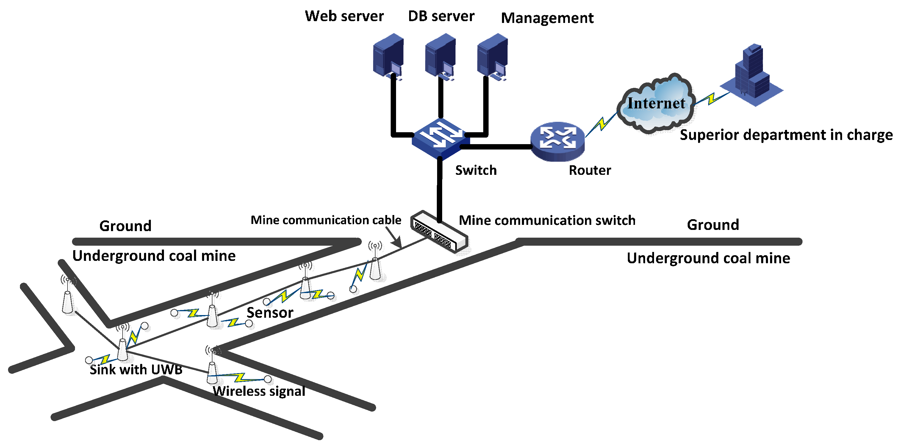
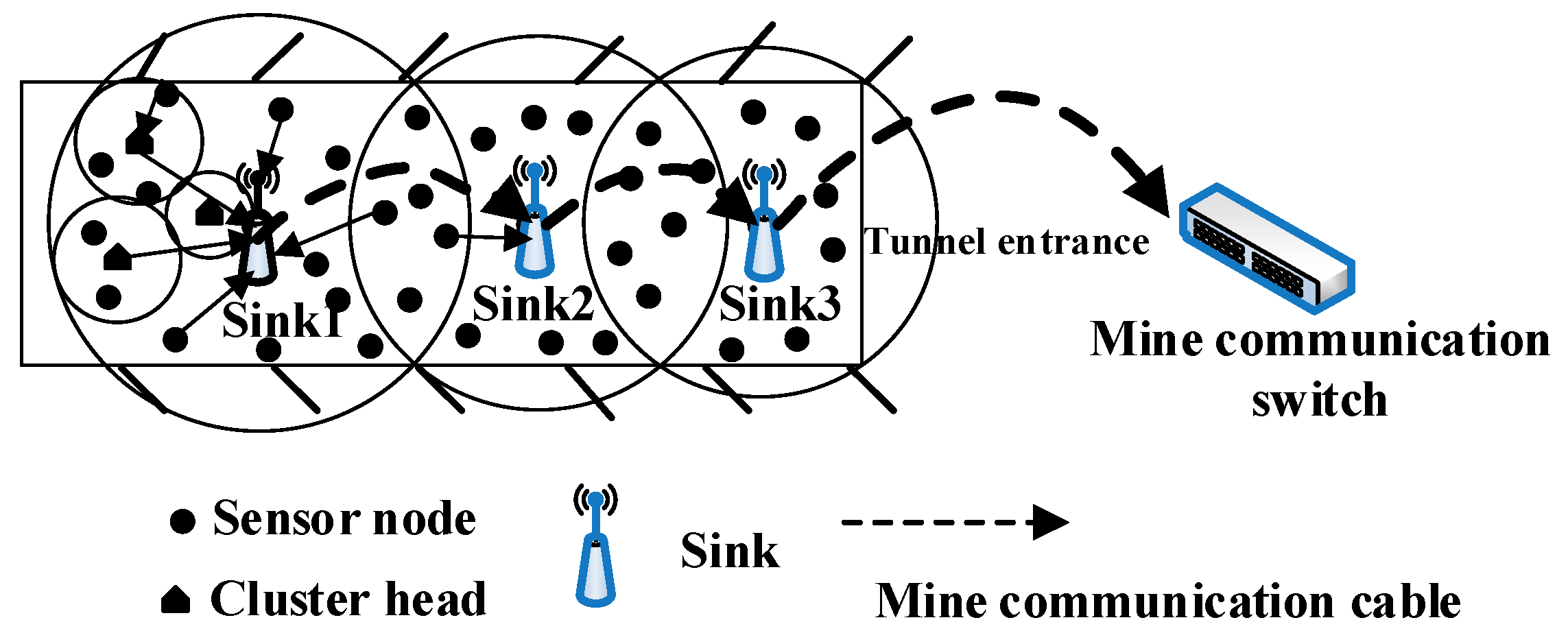
- The use of multisink WSNs in a coalmine tunnel to enable transmission of data to the sink in a rapid and timely manner.
- (2)
- The provision of a new routing protocol in a coalmine tunnel based on a multisink WSN structure.
- (3)
- The new algorithm has good network performance, including good connectivity, power efficiency, and delay.
- (4)
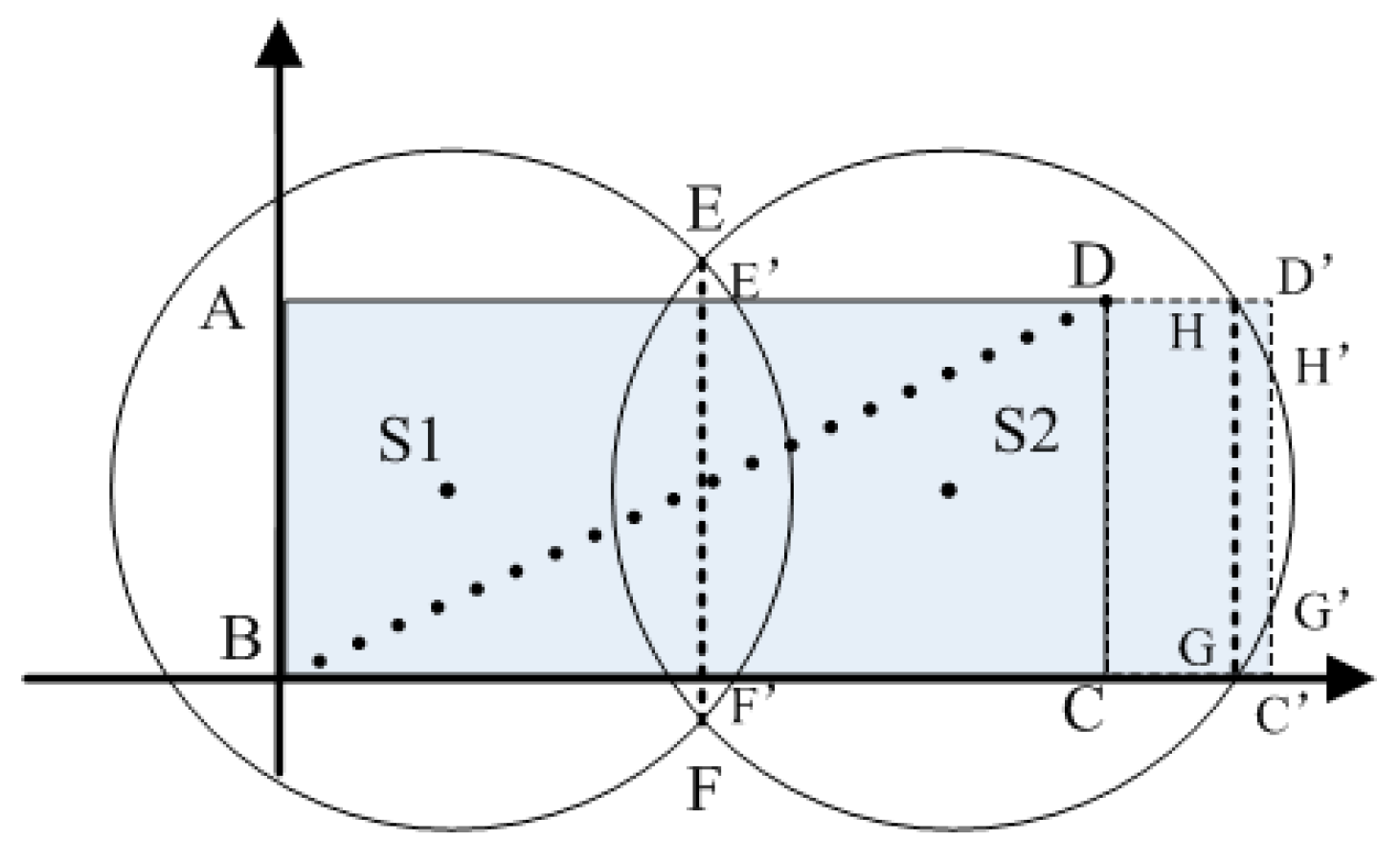
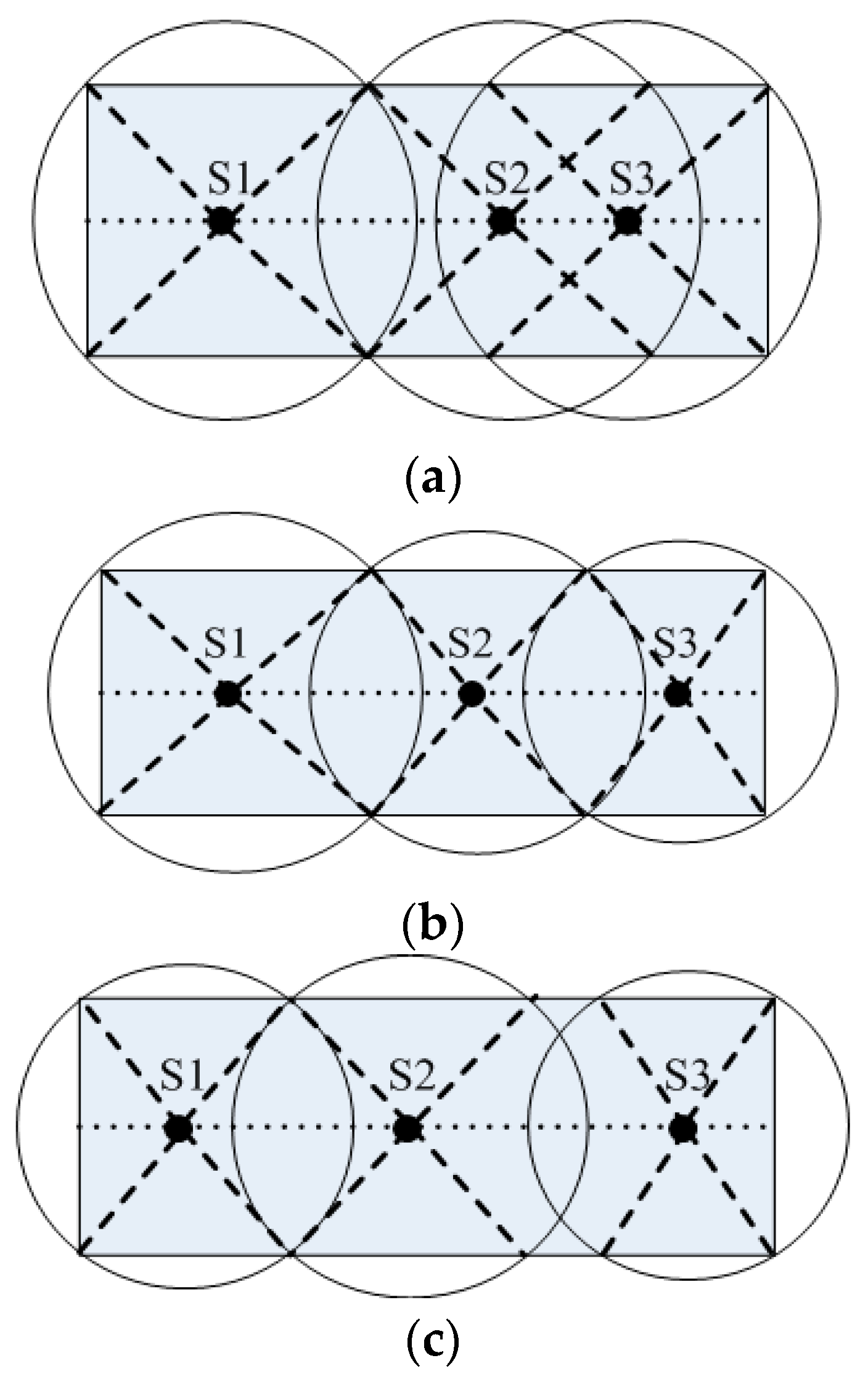
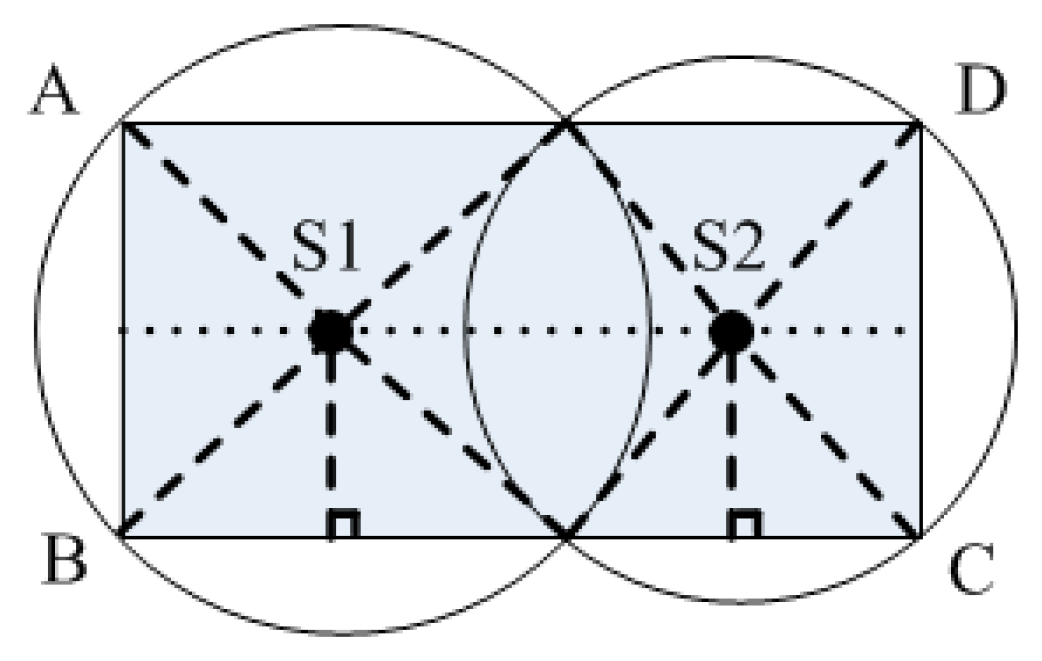
- By targeting underground coalmine tunnels with multisink WSNs, each sensor node can transmit data to the sink in either one hop or two hops.
2. Related Studies
3. Network and Power Control Model
3.1. Network Model
3.2. Power Control Model
4. Design of PCEB-MS Protocol
4.1. DPCA Algorithm
4.2. UCEBA Algorithm
4.2.1. Selection of the Candidate Cluster Head
4.2.2. Calculation of Unequal Radius
4.2.3. Selection of Final Cluster Head and Cluster Formation
| Algorithm 1: UCEBA Algorithm: unequal cluster algorithm | |
| Input: initial energy of the E0 node; residual energy of i of the Ecu(i) node; distance dtoSK between the candidate cluster head and the sink; the maximum distance Rmax between the candidate cluster head and the sink; duration of the competition of the candidate cluster head agreed in advance t0 | |
| Output: cluster head, unequal radius Rra | |
| 01: | Sensor nodes with the same sink ID form a region. |
| A sensor node in the overlapping region obtains two sink IDs and the distance between it and the two sinks is calculated. The sensor node then transmits data to the closer sink and does not need to join a cluster. | |
| 02: | Other sensor nodes that only have one sink ID are used to calculate u0 according to Equation (13), and are then compared with the threshold value, T; those with a value less than T become the candidate cluster head (if not, they become an ordinary sensor node). The unequal radius, Rra is then calculated according to Equation (14). |
| 03: | Each candidate cluster head broadcasts its competitive message, COMPETE_MSG, using a competitive radius Rra. |
| 04: | Each candidate cluster head starts timer, t, according to Equation (17). |
| 05: | The candidate cluster head is successfully competitive if each candidate cluster head does not receive the message SUCCESS_MSG from the neighbor candidate cluster head before t time is shown in its timer. This indicates that the candidate cluster head has been successfully competitive. After it becomes the cluster head, it then proceeds to 07; otherwise it proceeds to 06. |
| 06: | The candidate cluster head defects and quits the competition, thereby becoming an ordinary sensor node. |
| 07: | The candidate cluster head is successfully competitive, becomes a cluster head node, and sends a competition victory message, SUCCESS_MSG, to all neighboring candidate cluster head nodes. |
| 08: | The cluster head node broadcasts the competition victory message, CH_ADV_MSG, to the ordinary sensor nodes, using Rra as the radius. |
| 09: | The ordinary sensor node sends message, JOIN_CLUSTER_MSG, to notify the cluster head that it will become a cluster member node for sending data to the cluster head. |
| 10: | End |
5. Analysis of PCEB-MS
6. Evaluation of Algorithm Performance
6.1. Power Efficiency
6.2. Connectivity
6.3. Cluster Interference
6.4. Network Lifetime
6.5. Delay
7. Conclusions and Future Work
Acknowledgments
Author Contributions
Conflicts of Interest
References
- Xia, X.; Chen, Z.; Li, D.; Li, W. Proposal for Efficient Routing Protocol for Wireless Sensor Network in Coal Mine Goaf. Wirel. Pers. Commun. 2014, 77, 1699–1711. [Google Scholar] [CrossRef]
- Zhang, D.; Chen, Z. Energy-Efficiency of Cooperative Communication with Guaranteed E2E Reliability in WSNs. Int. J. Distrib. Sens. Netw. 2013. [Google Scholar] [CrossRef]
- Chen, R.S.; Wang, Y.F. Application Research of UWB Positioning Algorithm of Coal Mine Underground. Ind. Mine Autom. 2008, 12, 5–8. [Google Scholar]
- Bashir, S. Effect of Antenna Position and Polarization on UWB Propagation Channel in Underground Mines and Tunnels. IEEE Trans. Antennas Propag. 2014, 62, 4771–4779. [Google Scholar] [CrossRef]
- Manap, Z.; Ali, B.M.; Ng, C.K.; Noordin, N.K.; Sali, A. A review on hierarchical routing protocols for wireless sensor networks. Wirel. Pers. Commun. 2013, 72, 1077–1104. [Google Scholar] [CrossRef]
- Patel, H.; Pandya, N. Study and review of routing protocols for wireless sensor networks. Int. J. Eng. 2013, 2, 1–7. [Google Scholar]
- Wendi, B.H.; Anantha, P.C.; Hari, B. An Application-Specific Protocol Architecture for Wireless Microsensor Networks. IEEE Trans. Wirel. Commun. 2002, 1, 660–670. [Google Scholar]
- Wei, W.; Yong, Q. Information potential fields navigation in wireless Ad-Hoc sensor networks. Sensors 2011, 11, 4794–4807. [Google Scholar] [CrossRef] [PubMed]
- Manjeshwar, A.; Agrawal, D.P. TEEN: A routing protocol for enhanced efficiency in wireless sensor networks. In Proceedings of the IEEE International Parallel & Distributed Processing Symposium IPDPS, San Francisco, CA, USA, 23–27 April 2001.
- Oyman, E.I.; Ersoy, C. Multiple sink network design problem in large scale wireless sensor networks. IEEE Int. Conf. Commun. 2004, 3663–3667. [Google Scholar] [CrossRef]
- Dai, S.; Tang, C.; Qiao, S.; Xu, K.; Li, H.; Zhu, J. Optimal multiple sink nodes deployment in wireless sensor networks based on gene expression programming. In Proceedings of the International Conference on Communication Software and Networks (ICCSN), Singapore, 26–28 February 2010; pp. 355–359.
- Kim, D.; Wang, W.; Sohaee, N.; Ma, C.; Wu, W.; Lee, W.; Du, D.Z. Minimum Data-Latency-Bound k-Sink Placement Problem in Wireless Sensor Networks. IEEE/ACM Trans. Netw. 2011, 19, 1344–1353. [Google Scholar] [CrossRef]
- Das, D.; Rehena, Z.; Roy, S.; Mukherjee, N. Multiple-sink placement strategies in wireless sensor networks. In Proceedings of the IEEE 2013 5th International Conference on Communication Systems and Networks (COMSNETS), Bangalore, India, 7–10 January 2013.
- Erman, A.T.; Mutter, T.; van Hoesel, L.; Havinga, P. A cross-layered communication protocol for load balancing in large scale multi-sink wireless sensor networks. In Proceedings of the International Symposium on Autonomous Decentralized Systems (ISADS), Athens, Greece, 23–25 March 2009.
- Wang, C.; Wu, W. A load-balance routing algorithm for multi-sink wireless sensor networks. In Proceedings of the International Conference on Communication Software and Networks (ICCSN), Chengdu, China, 27–28 February 2009; pp. 380–384.
- Cheng, R.-H.; Peng, S.-Y.; Huang, C. A gradient-based dynamic load balance data forwarding method for multi-sink wireless sensor networks. In Proceedings of the IEEE Asia-Pacific Services Computing Conference (APSCC), Yilan, Taiwan, 9–12 December 2008; pp. 1132–1137.
- Yoo, H.; Shim, M.; Kim, D.; Kim, K.H. GLOBAL: A gradient-based routing protocol for load-balancing in large-scale wireless sensor networks with multiple sinks. In Proceedings of the IEEE Symposium on Computers and Communications (ISCC), Riccione, Italy, 22–25 June 2010; pp. 556–562.
- Paone, M.; Paladina, L.; Scarpa, M.; Puliafito, A. A multi-sink swarmbased routing protocol for wireless sensor networks. In Proceedings of the IEEE Symposium on Computers and Communications (ISCC), Sousse, Tunisia, 5–8 July 2009; pp. 28–33.
- Wang, W.; Li, W.; Chen, D.; Han, Y. Ant colony based routing algorithm for multi-sink networks. In Proceedings of the WRI World Congress on Computer Science and Information Engineering, Los Angeles, CA, USA, 31 March–2 April 2009; pp. 423–429.
- Isik, S.; Donmez M, Y.; Ersoy, C. Multi-sink load balanced forwarding with a multi-criteria fuzzy sink selection for video sensor networks. Comput. Netw. 2012, 56, 615–627. [Google Scholar] [CrossRef]
- Cheng, S.T.; Chang, T.Y. An adaptive learning scheme for load balancing with zone partition in multi-sink wireless sensor network. Expert Syst. Appl. 2012, 39, 9427–9434. [Google Scholar] [CrossRef]
- Wei, W.; Yang, X.L.; Shen, P.Y.; Zhou, B. Holes detection in anisotropic sensornets: Topological methods. Int. J. Distrib. Sens. Netw. 2012, 21, 3216–3229. [Google Scholar] [CrossRef]
- Wang, F.; Zhang, X.; Wang, M.; Chen, G. Energy-efficient routing algorithm for WSNs in underground mining. J. Netw. 2012, 7, 1824–1829. [Google Scholar] [CrossRef]
- Chen, W.; Jiang, X.; Li, X.; Gao, J.; Xu, X.; Ding, S. Wireless Sensor Network nodes correlation method in coal mine tunnel based on Bayesian decision. Measurement 2013, 46, 2335–2340. [Google Scholar] [CrossRef]
- Zhou, G.; Huang, L.; Zhu, Z.; Li, W.; Shen, G. A Zoning Strategy for Uniform Deployed Chain-Type Wireless Sensor Network in Underground Coal Mine Tunnel. In Proceedings of the 2013 IEEE 10th International Conference on High Performance Computing and Communications & 2013 IEEE International Conference on Embedded and Ubiquitous Computing (HPCC_EUC), Zhangjiajie, China, 13–15 November 2013; pp. 1135–1138.
- Hu, Y.; Liu, A. An efficient heuristic subtraction deployment strategy to guarantee quality of event detection for WSNs. Comput. J. 2015, 58, 1747–1762. [Google Scholar] [CrossRef]
- Wei, W.; Srivastava, H.M.; Zhang, Y.; Wang, L.; Shen, P.; Zhang, J. A local fractional integral inequality on fractal space analogous to Anderson’s inequality. Abstr. Appl. Anal. 2014, 2014, 797561. [Google Scholar] [CrossRef]
- Farjow, W.; Raahemifar, K.; Fernando, X. ‘Novel Wireless Channels Characterization Model for Underground Mines’ Applied Mathematical Modeling. Appl. Math. Model. 2015, 39, 5997–6007. [Google Scholar] [CrossRef]
- Latif, S.; Fernando, X. A Greener MAC Layer Protocol for Smart Home Wireless Sensor Networks. In Proceedings of the 2013 IEEE Online Conference on Green Communications, Piscataway, NJ, USA, 29–31 October 2013; pp. 169–174.
- Saleh, A.; Valenzuela, A. A Statistical Model for Indoor Multipath Propagation. IEEE J. Sel. Area Commun. 1987, 5, 128–137. [Google Scholar] [CrossRef]
- Saunders, S.R. Antennas and Propagation for Wireless Communication Systems; John Wiley & Sons Ltd.: Chichester, UK, 1999. [Google Scholar]
- Woo, A.; Terence, T.; Culler, D. Taming the Underlying Challenges of Reliable Multihop Routing in Sensor Networks. In Proceedings of the Conference on Embedded Networked Sensor Systems, Los Angeles, CA, USA, 5–7 November 2003.
- Liu, X.; Yan, J.; Miao, J.; Xu, W.; Tu, X. Improvement on LEACH Agreement of Mine Wireless Sensor Network. Coal Sci. Technol. 2009, 37, 46–49. [Google Scholar]
- Wei, W.; Yang X, L.; Zhou, B.; Feng, J.; Shen, P.-Y. Combined energy minimization for image reconstruction from few views. Math. Probl. Eng. 2012, 16, 2213–2223. [Google Scholar] [CrossRef]
- Tang, Z.; Liu, A.; Huang, C. Social-aware Data Collection Scheme through Opportunistic Communication in Vehicular Mobile Networks. IEEE Access 2016, 4, 6480–6502. [Google Scholar] [CrossRef]
- Liu, X.; Wei, T.; Liu, A. Fast Program Codes dissemination for Smart Wireless Software Defined Networks. Sci. Programm. 2016, 2016, 6907231. [Google Scholar] [CrossRef]
- Jiang, H.; Sun, R.; Ma, S. Energy Optimized Routing Algorithm for Hybrid Wireless Mesh Networks in Coal Mine. Int. J. Distrib. Sens. Netw. 2015, 2015. [Google Scholar] [CrossRef]
- Shen, J.; Liu, D.; Ren, Y.; Ji, S.; Wang, J.; Choi, D. A Mobile-Sink Based Energy Efficiency Clustering Routing Algorithm for WSNs in Coal Mine. In Proceedings of the International Conference on Advanced Cloud & Big Data, YangZhou, China, 30 October–1 November 2015; pp. 267–274.
- Qiao, G.; Zeng, J. An Underground Mobile Wireless Sensor Network Routing Protocol for Coal Mine Environment. J. Comput. Inform. Syst. 2011, 7, 2487–2495. [Google Scholar]
- Heinzelman, W.; Chandrakasan, A.; Balakrishnan, H. An application-specifid protocol architecture for wireless microsensor networks. IEEE Trans. Wirel. Commun. 2002, 1, 660–670. [Google Scholar] [CrossRef]
- Wang, A.; Heinzelman, W.; Chandrakasan, A. Energy-scalable protocols for battery-operated microsensor networks. In Proceedings of the 1999 IEEE Workshop on Signal Processing Systems (SiPS ’99), Taipei, Taiwan, 20–22 October 1999; pp. 483–492.
- Wei, W.; Fan, X.; Song, H.; Fan, X.; Yang, J. Imperfect information dynamic stackelberg game based resource allocation using hidden Markov for cloud computing. IEEE Trans. Serv. Comput. 2016. [Google Scholar] [CrossRef]
- Zhang, D.; Chen, Z.; Ren, J.; Zhang, N.; Awad, M.K.; Zhou, H.; Shen, X. Energy Harvesting-Aided Spectrum Sensing and Data Transmission in Heterogeneous Cognitive Radio Sensor Network. IEEE Trans. Veh. Technol. 2016. [Google Scholar] [CrossRef]
- Hu, L. Distributed code assignments for CDMA packet radio networks. IEEE/ACM Trans. Netw. 1993, 1, 668–677. [Google Scholar]
- Zhang, D.; Chen, Z.; Zhou, H.; Chen, L.; Shen, X. Energy-balanced cooperative transmission based on relay selection and power control in energy harvesting wireless sensor network. Comput. Netw. 2016, 104, 189–197. [Google Scholar] [CrossRef]
- Akkaya, K.; Younis, M. COLA: A Coverage and Latency Aware Actor Placement for Wireless Sensor and Actor Networks. In Proceedings of the IEEE Vehicular Technology Conference, Montreal, QC, Canada, 25–28 September 2006.




| ID | State | Residual Energy (J) | Distance to Sink (m) |
|---|---|---|---|
| 3 | Candidate | 1.38 | 10 |
| 7 | Candidate | 0.21 | 20 |
| 8 | Candidate | 0.15 | 80 |
| 5 | Candidate | 0.38 | 60 |
| Parameters | Values |
|---|---|
| Network coverage | (0, 0)–(1000, 20) m |
| Number of sink nodes | 1–12 |
| n | 200 |
| Initial energy of sensor node | 0.5 J |
| εmp | 0.0013 pJ/bit/m4 |
| EDF | 5 nJ/bit/signal |
| εfs | 10 pJ/bit/m2 |
| Eelec | 50 nJ/bit |
| t0 | 4 s |
| Data grouping | 512 bit |
| gt | 25 dBi |
| gr | 25 dBi |
| λ | 0.1 |
© 2016 by the authors; licensee MDPI, Basel, Switzerland. This article is an open access article distributed under the terms and conditions of the Creative Commons Attribution (CC-BY) license (http://creativecommons.org/licenses/by/4.0/).
Share and Cite
Xia, X.; Chen, Z.; Liu, H.; Wang, H.; Zeng, F. A Routing Protocol for Multisink Wireless Sensor Networks in Underground Coalmine Tunnels. Sensors 2016, 16, 2032. https://doi.org/10.3390/s16122032
Xia X, Chen Z, Liu H, Wang H, Zeng F. A Routing Protocol for Multisink Wireless Sensor Networks in Underground Coalmine Tunnels. Sensors. 2016; 16(12):2032. https://doi.org/10.3390/s16122032
Chicago/Turabian StyleXia, Xu, Zhigang Chen, Hui Liu, Huihui Wang, and Feng Zeng. 2016. "A Routing Protocol for Multisink Wireless Sensor Networks in Underground Coalmine Tunnels" Sensors 16, no. 12: 2032. https://doi.org/10.3390/s16122032
APA StyleXia, X., Chen, Z., Liu, H., Wang, H., & Zeng, F. (2016). A Routing Protocol for Multisink Wireless Sensor Networks in Underground Coalmine Tunnels. Sensors, 16(12), 2032. https://doi.org/10.3390/s16122032


