1. Introduction
The need for positioning and localization has increased over the decades, relying mostly on GPS to fulfill the task. However, indoor environments, among other scenarios, such as urban canyons, are satellite-denied environments; which makes it infeasible to rely on GPS. To overcome this challenge, research on non-satellite-based solutions has experienced a rapid growth during the last few years. The diversity of solutions is overwhelming. Technology and algorithmic choices condition each system’s strengths and weaknesses, thus making them suitable only for certain applications.
We focus ourselves on mass market applications. The evolution of micro-electromechanical systems (MEMS) in cost, size and quality made it possible for these to be embedded in every smartphone. Nevertheless, the mass market does not end here. We foresee a growth in the demand of smart devices, with smartwatches among them. This implies larger amounts of position-related information available. MEMS accelerometers and gyroscopes comprise an inertial measurement unit (IMU), and their first use in smartphones was to determine the orientation, landscape or portrait, of the device. In recent years, there has been an increasing interest in developing pedestrian dead-reckoning (PDR) algorithms based on an IMU embedded in a smartphone.
There are two types of PDR, the strapdown algorithm and the step-length-and-heading-estimation approach. Standard strapdown algorithms [
1] use turn rates to keep track of the IMU orientation, thus being able to subtract the gravity effect from the accelerometer signal. Then, the corrected acceleration is used to compute the position by double integration. The accumulated error in the position due to the integration of current MEMS inertial sensor readings is prohibitively high. Possible solutions are zero-velocity updates (ZUPTs) [
2], though these require a foot-mounted IMU to detect the foot stance phase.
The step-length-and-heading-estimation approach sequentially estimates the pedestrian’s position based on a previous computed position and an estimation of both the step length and direction of the walk, also known as heading [
3]. A well-known approach to identify steps is to detect changes in the vertical displacement of the pelvis as in [
4]. Other options are to find a model based on the acceleration signal in the time domain [
5,
6] or in the frequency domain [
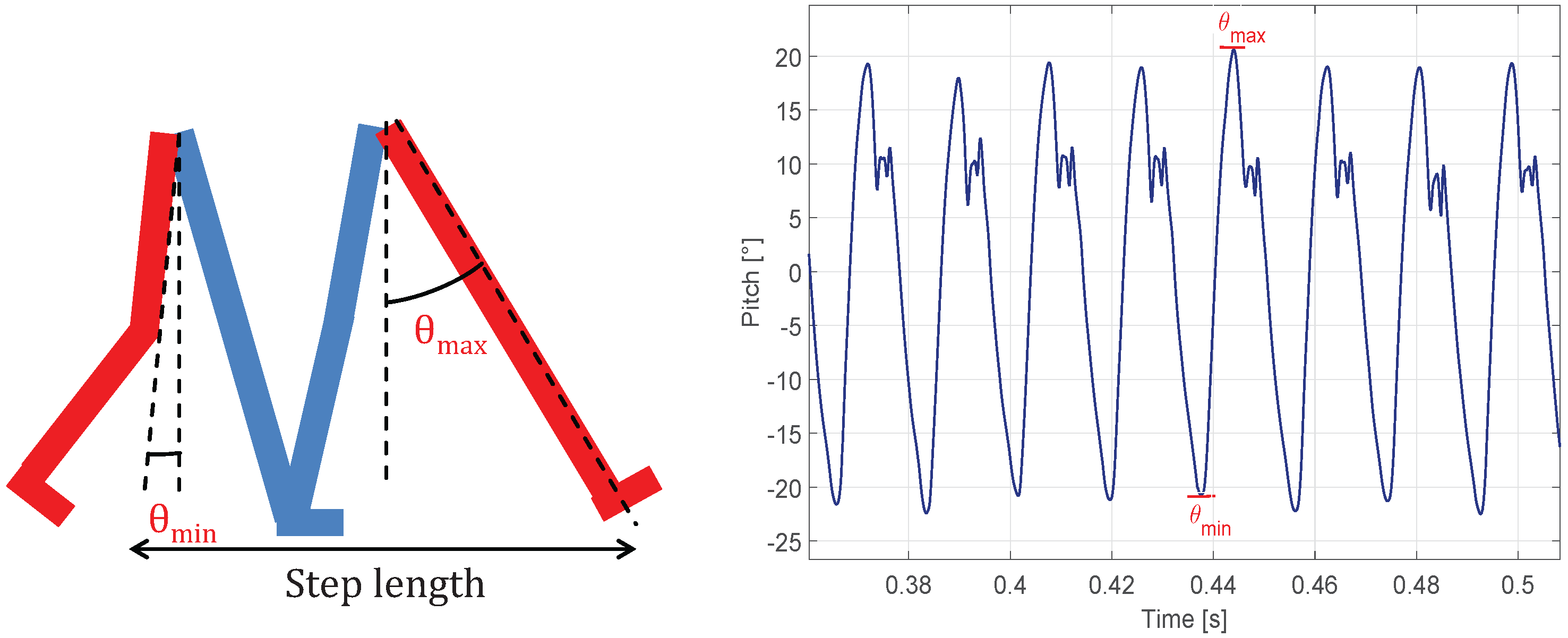
7]. Most recent approaches use a pitch-based model for pocket-mounted IMUs [
8].
The problems of inertial positioning systems can be circumvented by the development of hybrid systems that combine the inertial measurements with position estimations from network-based positioning algorithms. These systems estimate the user’s position through the communication of the user with a wireless network (WiFi, LTE, ultra-wide band (UWB), wireless sensor networks (WSN), Bluetooth). Traditionally, these systems have been classified depending on the way the distance between any two nodes of the network is estimated. There are methods based on the time of arrival (ToA), methods based on the angle of arrival (AoA) and methods based on the received signal strength (RSS) [
9,
10,
11]. Nowadays, ToA methods employing UWB signals show encouraging results [
12,
13]. However, and focusing on our target of mass market applications, RSS-based methods based on WiFi networks are the most suitable option since WiFi networks are deployed all around the world in millions of buildings.
The combination of RSS-based methods and inertial methods can be done in multiple ways. For example, in [
14,
15], the authors use the RSS to compute the initial location of the user. Other authors use a Kalman filter (KF) to combine the RSS and inertial measurements [
16,
17,
18]. It is also common to employ different fusion algorithms as in [
19,
20], where an extended Kalman filter (EKF) is used, or in [
21], where the authors use a particle filter (PF). As an alternative, digital information of the map of the building can be used to enhance the position estimation [
22,
23]. Unfortunately, the information of the map is not always available for positioning purposes.
Particularizing for the problem of interest in this work, i.e., indoor positioning systems based on smartphones, we can find related works in the literature as [
24], where the authors present an indoor tracking system for underground public transportation based on inertial measurements and information about the route and average time between stops. Other authors estimate the relative position of the smartphone with respect to the user, which is mandatory for the transformation of the inertial measurements from the smartphone coordinate frame to the navigation coordinate frame; in [
25], the authors use a least square support vector machine (LS-SVM). However, in order to increase the accuracy of the system, the authors typically predefine the position of the smartphone; an example can be found in [
6], where the authors propose a pure inertial-based positioning system specifically designed for smartphones. The main disadvantage of pure inertial systems is that they suffer from the inertial drift, and therefore, the error increases with time. To avoid the effects of the inertial drift, the authors use hybrid solutions that fuse the inertial measurements with RSS measurements. The authors in [
26] formulate the fusion of the RSS with the inertial measurements through a hidden Markov model (HMM). Alternatively, in [
27], the fusion algorithm used is the sequential Monte Carlo Kalman filter. In [
28] the authors combine the inertial measurements with RSS and magnetic fingerprinting using a KF. The accuracy of this system is typically around 3
. Another approach to improve the accuracy is the simultaneous localization and mapping (SLAM) approach, as in [
29,
30], but the accuracy is only increased if the path walked by the user forms closed loops. An alternative is the use of information about the floor plan or landmark points (stairs, elevators, doors, etc.) [
31,
32,
33]. This approach increases the accuracy of the system, but cannot be generalized, as the map of the building is not always available.
Nevertheless, a major problem with these kinds of systems when applied to mass market applications is the lack of control over the WiFi network. The design of WiFi networks is traditionally done for communications purposes, and therefore, it introduces problems when used for positioning applications; for example: (i) the lack of measurements from different anchor nodes or (ii) the quality of the RSS measurements for distance estimations due to the density of the nodes of the network. So far, however, there has been little discussion about the effects of the application of positioning systems to a new scenario where the WiFi network is not controlled by the designer of the positioning system. In this work, we identify and evaluate these effects and present a method that ameliorates them by introducing a second WiFi receiver in the system. Particularly, we will use the RSS measurements obtained with a smartphone and a smartwatch. We design a new method for combining RSS measurements from different receivers and inertial measurements from a low-cost IMU embedded in a commercial smartphone placed in the pocket of the user. The result is a pedestrian positioning system that runs in commercial smartphones and smartwatches, and thus, it is suitable for mass market applications. The main contributions of this work are: (i) the design of an indoor positioning system based on inertial measurements and the combination of RSS measurements from different sources (a smartphone and a smartwatch) using a GMM algorithm that improves the accuracy of the distance estimations; (ii) the identification and evaluation of the network deployment and network management issues (see
Section 4) produced by the lack of control over the WiFi network that negatively affect the performance of positioning systems; and (iii) the experimental validation of the designed positioning system in a real scenario of 6000
without any control over the network and using commercial smartphones.
The rest of this paper is organized as follows:
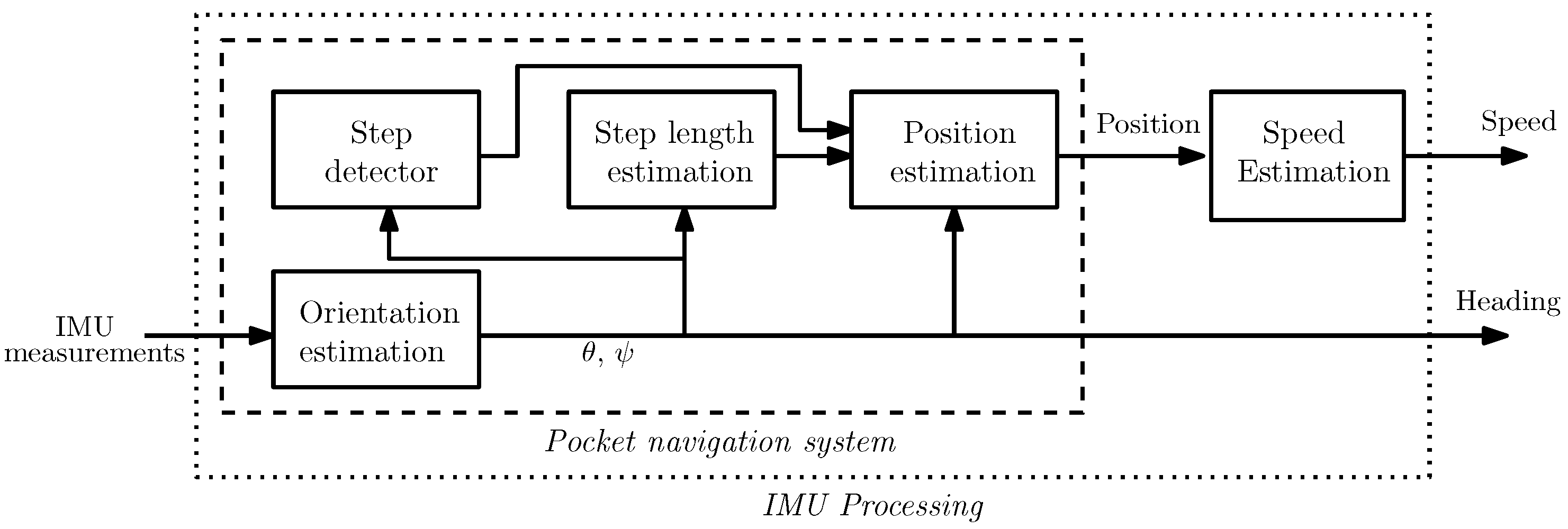
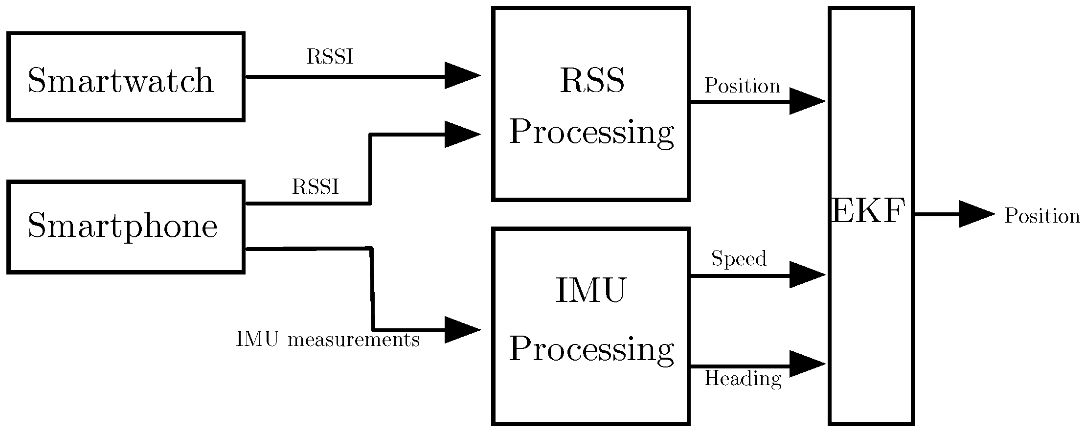
Section 2 introduces the architecture of the system.
Section 3 details the algorithms employed to obtain the speed and the heading of the user from the inertial measurements. In
Section 4, we describe the method used for computing the position estimation from the RSS measurements. The combination of inertial and RSS measurements is explained in
Section 5, and
Section 6 presents the experimental validation. Finally, the conclusions of the work are presented in
Section 7.
4. RSS Processing Block
This section details the algorithms employed to obtain position estimations from the RSS measurements. Traditionally, the position estimation is divided into two steps. First, the RSS is computed from an existing wireless network and transformed to distance estimations following a path loss model. Afterwards, the distance estimations are combined through a multilateration method to obtain the position estimation. The network selection is crucial for the design of an indoor positioning system. Among all possible network technologies that provide RSS measurements (WiFi, LTE, UWB, WSN, Bluetooth, etc.), we choose the WiFi technology because it has an outstanding advantage among all of the others: WiFi networks are currently deployed around the world in millions of buildings. Therefore, our system can be used in mass market applications without the need for any inversion in the network infrastructure. Unfortunately, WiFi networks are typically designed for communications and not for positioning applications. This fact generates some issues that must be amended in order to minimize the error of the positioning system. These issues can be divided into two groups: (i) network deployment issues; and (ii) network management issues.
4.1. Network Deployment Issues
The design of the network deployment for communication purposes tries to maximize the coverage area of the network with the minimum possible number of nodes. This minimization can be subjected to constraints as for example to assure a minimum QoS for the network in all of the area. These constraints can increase the number of anchor nodes, but generally, network designers are reluctant to increase the number of nodes as this increases the cost of the network infrastructure. This main design objective is contrary to the interest of positioning systems. The main issues follow:
Reception from at least three anchor nodes: It is necessary to receive from at least three anchor nodes in order to obtain a 2D position estimation. Due to the low density of anchor nodes, there will be areas where the user will not receive from three of them. Note that this issue is magnified when the user only receives measurements from one anchor node.
Distance to anchors: The mean distance between any anchor node and the mobile user is inversely proportional to the number of nodes. In combination with larger estimation errors at longer distances [
36], the mean distance will affect the accuracy of the position estimations.
Collinearity of anchor nodes: collinear anchors produce higher position estimation errors. The deployment of the nodes in a communication network does not take into account the collinearity of the nodes. Disregarding this issue will impinge on the performance of the positioning system.
4.2. Network Management Issues
The management of a communication network can respond to many different objectives, so it is difficult to analyze them in general. Notwithstanding, there are several configuration issues that can affect the performance of a positioning system:
Transmitted power: Beyond the obvious relationship between the distance and the RSS, which is directly related to the transmitted power, the transmitted power also affects the coverage area of the anchor nodes, which can lead to the issues commented in the network deployment section (reception from at least three anchor nodes and distance to anchors).
WiFi channel: Without controlling the network, the user is unaware of the transmission channel of the anchor nodes. Therefore, it has to scan all of the frequency channels in order to obtain the RSS, which increases the measurement time and reduces the number of measurements. Note that a reduction in the number of measurements means a reduction in the number of different anchor nodes received simultaneously.
Beacon period of anchor nodes: Anchor nodes periodically send beacon signals, which are used to estimate the RSS. The periodicity of these signals affects directly the performance of the positioning system, as it determines the number of RSS estimations available for the user.
Synchronization between anchor nodes: The synchronization between the anchor nodes is critical if we want to obtain at least three simultaneous RSS readings in order to compute a 2D position estimation.
The above issues can appear alone or in groups in an indoor positioning system. These issues are not commonly treated in the literature, as total control of the network is typically assumed, that is these issues are amended in the network configuration and design phase. However, without controlling the WiFi network, new ways of designing indoor positioning systems have to be considered. In this work, our approach is the introduction of a secondary receiver that ameliorates these issues. Focusing on our target of mass market applications, we will consider a smartwatch as the second receiver. These devices are nowadays increasing in popularity among consumers, and it is expected that they will be widely used in the near future.
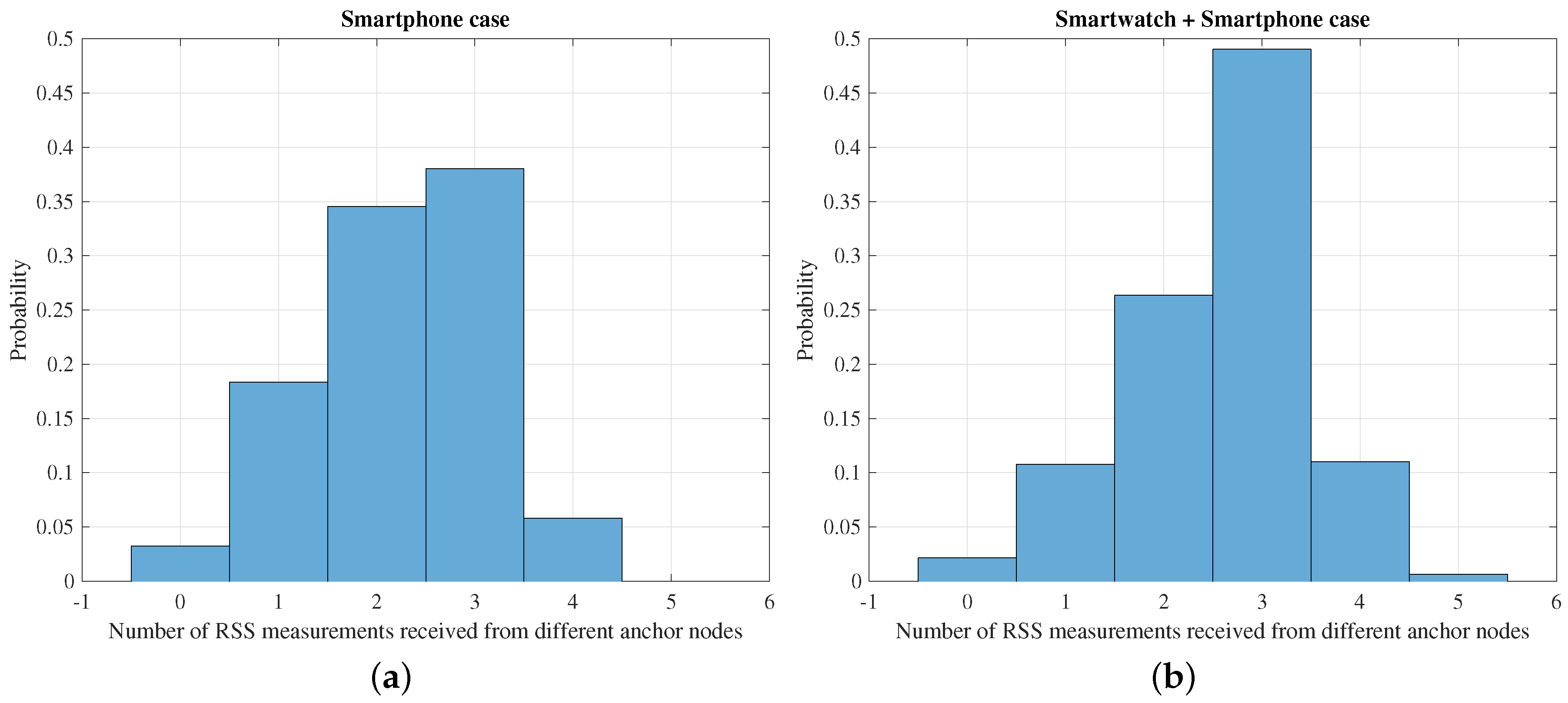
The benefits of using a smartwatch as a secondary receiver in our system are mainly two: (i) an improvement in the accuracy of the distance estimations; and (ii) an increase in the number of measurements. On the one hand, the improvement in the accuracy of the distance estimations is achieved thanks to the combination of the RSS measurements from the two devices. By combining the RSS of two sources, the variability of the measurements is reduced. Note that we can consider that the noise of both measurements is statistically independent. Therefore, the accuracy of the distance estimation is increased. On the other hand, the increase in the number of measurements is produced by the fact that we have two devices independently scanning the WiFi channels, and therefore, the odds of receiving more measurements are increased.
Figure 4 shows the normalized histogram of the number of RSS measurements from different anchor nodes received by the system at each time instant. In Case A, only the smartphone is used to obtain the measurements, and in Case B, the smartphone and smartwatch measurements are used. An increase of the number of times that the system has received from three or more different anchor nodes can be observed, which results in an increase in the accuracy of the position estimation, as is shown in
Section 6. Particularly, in Case A, the number of times that the system has received from more than three anchor nodes represents 44% of times, whereas in Case B, this number rises up to 61%.
4.3. Distance Estimation
Typically, the estimation of distance from the RSSI uses the log-distance path loss model [
9], that is,
where
P is the received power,
is the received power at one meter from the transmitter,
α is the path-loss exponent,
d is the distance and
models the shadowing effects. Considering this model, the RSS follows a Gaussian distribution:
However, this model was developed for the single receiver case and does not take into account the scenario proposed in this work where the user carries two different receivers. As an alternative, in this work, we propose the use of Gaussian mixture models (GMM). The idea behind the mixture models is to obtain a new distribution from a linear combination of known distributions, Gaussian in the case of GMM. By using a sufficient number of Gaussians and by adjusting their means and covariances, as well as the coefficients in the linear combination, almost any continuous density can be approximated to arbitrary accuracy [
37]. We consider a superposition of
K Gaussian distributions of the form,
where
are the so-called mixing coefficients and
and
are, respectively, the mean and covariance of the Gaussian densities used (also known as components of the mixture). In order to use the GMM in the distance estimation, we need to compute the parameters of the model, i.e.,
,
and
, from a set of observations obtained in a calibration phase. Lets us denote
X as the set of
N observations obtained from the calibration phase, that is a set of
N vectors
, where
are the RSS received by the smartphone,
the RSS received by the smartwatch and
d the real distance from the user to the anchor node. Assuming that the data points are drawn independently from the distribution, the log likelihood function is given by,
We compute the parameters of the model as the values that maximize the log likelihood function. The maximization of the log likelihood function of a GMM is a complex problem and does not have a closed solution. Traditionally, the maximization problem is solved using the expectation maximization (EM) algorithm [
38]. The EM algorithm is an iterative method that maximizes the log likelihood function in each iteration following a two-step procedure: the expectation step (E-step) and the maximization step (M-step). [
37]. In the E-step, we compute the so-called responsibilities
from the current estimation of the parameters, that is,
while in the M-step, we re-estimate the parameters using the computed responsibilities, that is,
where:
These two steps are iteratively repeated until the increment of the log likelihood function in the current iteration is below a convergence threshold.
As previously stated, in this work, we do not have any control of the wireless network. This will produce a lack of synchronization between the RSS measurements of the receivers, and therefore, we have to consider different situations:
Case A: In this case, we obtain a measurement of the RSS from a specific anchor node in both receivers at a quasi-simultaneous time. Then, we can compute the estimated distance using the RSS obtained by both devices. Therefore, we define a vector of observation .
Case B: In this case, we receive RSS measurements only from the smartphone. Then, we define the observation vector as .
Case C: This is similar to Case B, but we receive RSS measurements from the smartwatch instead of the smartphone; the observation vector is .
We use a different GMM for each one of the three cases, that is we estimate the parameters
,
and
for the log likelihood function of each one of the cases. The difference between the models is the vector of observations
X. Once we have estimated the parameters of the models using the data obtained in the calibration phase and the EM algorithm, we estimate the distance solving the following maximization problem:
where the maximization of the log likelihood function is done with respect to the distance because it is the only unknown variable in the vector of observation
X; the
and
variables are known as they are the RSS measurements received from the smartphone and the smartwatch.
4.4. Position Computation
As stated in the beginning of this section, the estimation of position based on RSS measurements is a two-step procedure. Once the distances to the anchor nodes are estimated, we must combine them to obtain the position of the user. In this work, we use a weighted least squares algorithm (WLS). The WLS estimates the user position in order to minimize the overall squared error of the distance measurements. In other words, the position is computed as the solution to the following minimization problem [
39],
where
is the set of distance measurements available at time instant
k and
are the weights of the algorithm [
40]. Note that due to the logarithmic relationship between the RSS and the distance, the accuracy of the estimations depends on the distance to be estimated itself [
36], and hence, it is meaningful to assign different weights to estimations with different accuracies [
41]. The problem in Equation (
21) can be solved in an iterative way following a gradient descent approach.
5. Filtering Block
The third block of the system architecture is the filtering block. Here, we combine the estimations of the position, speed and heading of the user into a single filter that outputs an enhanced estimation of the user’s position. In this work, we have employed the EKF, which is an extension of the KF designed to cope with non-linear models [
42]. Although the PF is a common option in the related works due to its ability to adapt to non-Gaussian measurement errors, the use of a PF increases the computational complexity of the system. Our objective is to design a system for mass market applications; thus, the overall computational complexity and its associated battery consumption must be reduced. For this reason, we choose the EKF algorithm, which presents a good balance between positioning accuracy and computational complexity.
Let us model the state of a person in a two-dimensional space by means of its position and velocity,
where
represent the position in Cartesian coordinates,
is the speed and
the heading of the user. The EKF algorithm is divided into two steps: (i) the prediction step; and (ii) the correction step. In the prediction step, the a priori estimation of the state vector
and the state covariance
are updated using the kinematic model,
where
k is the time step,
is the transition matrix,
is a zero mean Gaussian noise with covariance matrix
and
is the Jacobian matrix of the partial derivatives of the model function
with respect to
. The transition matrix is defined following the constant velocity model with the velocity represented in polar coordinates, that is,
where
T is the time period between measurements. In the second step of the method, i.e., the correction step, the previous predictions are corrected thanks to the measurements and the so-called Kalman gain
[
43], that is,
where
is the measurement matrix, the identity matrix in our case,
is the measurement vector and
is the measurement noise covariance matrix.
The EKF exploits the statistics of the measurements in order to produce an enhanced estimation of the state vector. These statistics are considered to be known by the designer and are introduced to the filter through the configuration of the covariance matrices
and
. In this work, we assume that the state variables and measurement variables are independent, and therefore, we configure their covariance matrices as diagonal matrices. The values of the variances are manually configured based on our experimental results. The specific values used are:
The following section validates the performance of the designed pedestrian tracking system in a real environment.
6. Experimental Validation
In this section, we test the performance of the indoor positioning system designed. To evaluate the performance, we have used a Motorola Moto G2 LTE smartphone and a Nexus 5 smartphone, which will take the roll of the smartwatch once attached to the wrist of the user. Both smartphones include a 6-DoF IMU with an accelerometer and a gyroscope. The sensors are sampled with a frequency of 100 Hz with our own designed Android application that also scans the WiFi channels to obtain the RSS measurements. As stated in
Section 3, the obtained frequency is not always 100 Hz, and our system has to adapt to small changes in the measurement rate. The system updates the estimation of the user’s position every second using the inertial and RSS measurements received since the last estimation update.
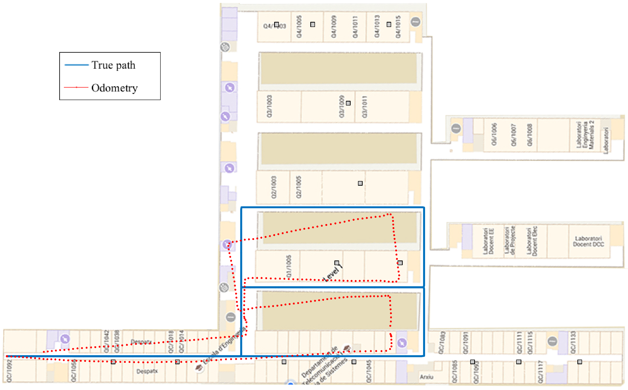
The scenario of validation is the first floor of the Engineering School at the Universitat Autònoma de Barcelona (see
Figure 5). The scenario is an area of approximately
covered with 14 WiFi access points that will act as the anchor nodes of the system, that is an anchor node every
. Note that there is no control about the configuration nor the placement of the anchor nodes as far as we are using the available WiFi network at the building. Note also that the distribution of the anchor nodes is not uniform around the area, and there are zones far from any anchor nodes, zones with high density of anchor nodes and zones with collinear anchors nodes. This is the reason for choosing this scenario; the selected scenario presents all of the typical issues of a communication network described in
Section 4.
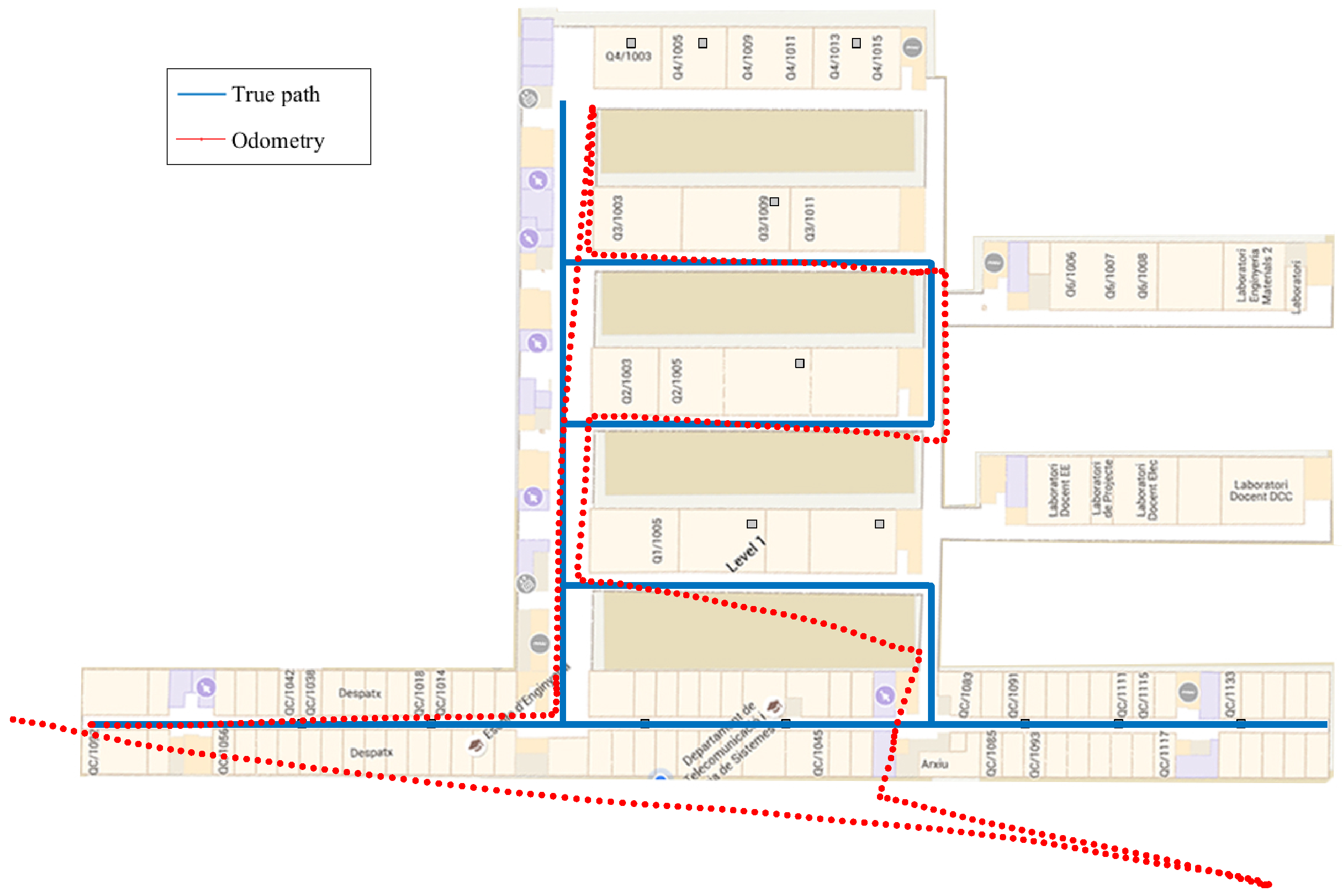
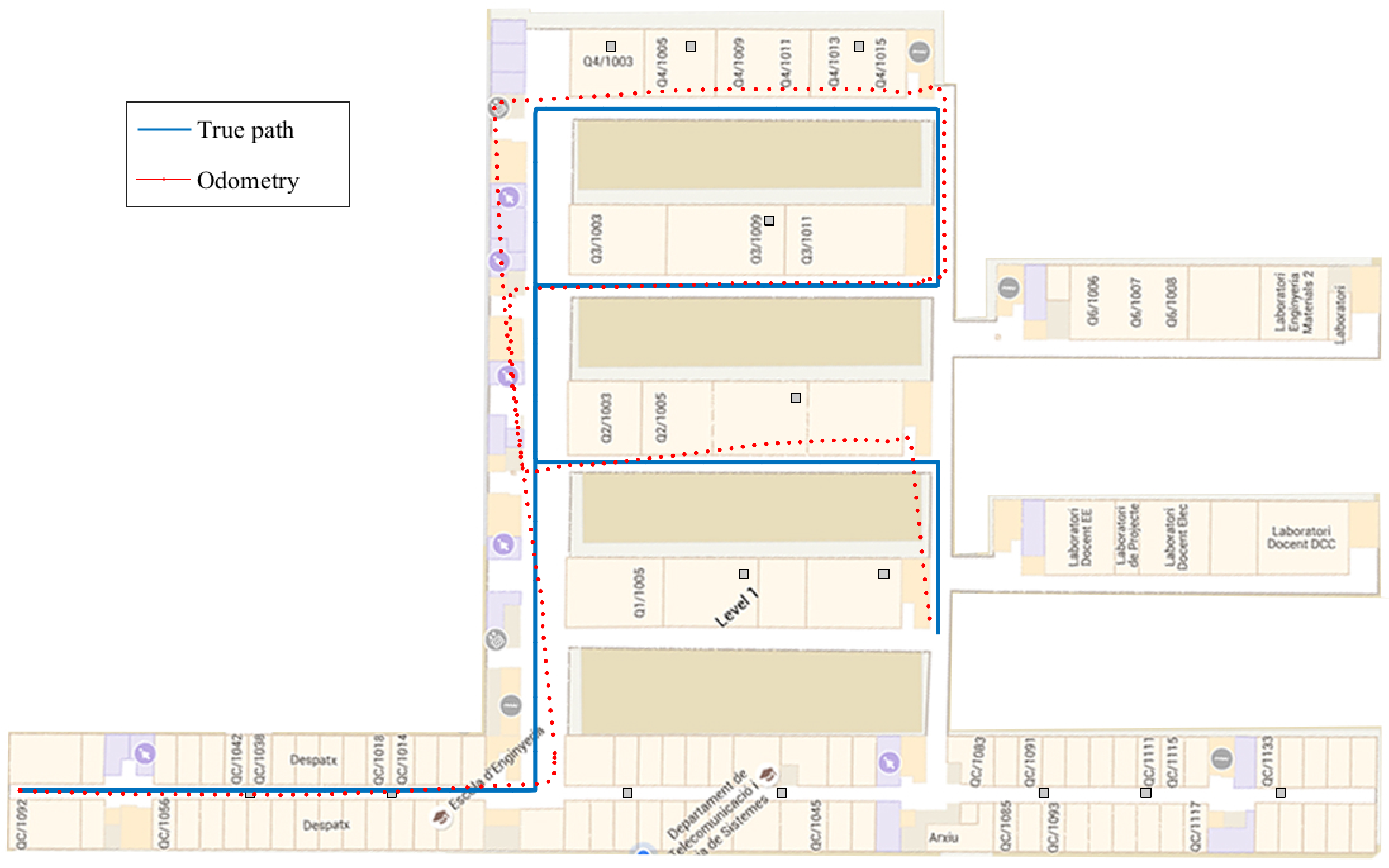
In order to evaluate the indoor positioning system, we have considered three different paths.
Figure 5 depicts the trajectory of Path 1 with a length of
. The second path, i.e., Path 2, is shown in
Figure 6, and it has a length of
. Finally, Path 3 is shown in
Figure 7, and it has a length of
.
During the experimental validation, we compare five different methods: (i) a step-length-and-heading-estimation algorithm based on the inertial measurements from the smartphone; (ii) a WLS approach based on the distance estimations obtained from the RSS measurements of the smartphone; (iii) an EKF that combines the estimations of the previous WLS (only based on the smartphone) with the inertial measurements; (iv) a WLS based on the distance estimation obtained from the combination of the RSS measurements of the smartphone and the smartwatch; and (v) an EKF that combines the inertial measurements with the WLS based on the smart combination of the smartphone and smartwatch. In the following, these methods are referred to as IMU, WLS-phone, EKF-phone, WLS-smart and EKF-smart, respectively.
In order to evaluate the performance of the different methods, we compute the real path of the user using a series of landmarks deployed around the building. We ask the user of the system to press a button every time that he/she goes near a landmark. Then, the times are stored, and the real path is calculated by assuming a constant speed of the user between two landmarks. With the appropriate number of landmarks, the resultant error of the obtained real path can be considered negligible.
Table 1 shows the results obtained during the experimental validation in terms of the RMSE. We have selected the paths in order to be representative of a real scenario. For this reason, we have selected two paths where the IMU has a considerable drift (Path 1 and Path 2) and one path where the drift of the IMU is small (Path 3). The odometry of the selected paths is shown in
Figure 5,
Figure 6 and
Figure 7. Results show the improvement in the positioning accuracy due to the use of a second mobile receiver. In particular, the improvement of the WLS-smart over the WLS-phone is around 30% in the case of Path 1, 23% in Path 2 and 37.5% in Path 3. For the EKF-smart system, the improvement over the EKF-phone is around 35% in the case of Path 1, 19% in the case of Path 2 and 22% in Path 3. If we consider the improvement of the EKF-smart system compared with the IMU system, we obtain an improvement of 56% for Path 1, 35% for Path 2 and 12.5% for Path 3. The comparison between the WLS-smart method and the WLS-phone method gives us an idea about the improvement produced by the use of a second receiver in the system. The increment in the accuracy of the estimation is produced by two main factors. First, the combination of the RSS from the smartphone and the smartwatch results in an increment in the accuracy of the distance estimation. Second, the use of two receivers increases the number of measurements available. Specifically, the increase in the number of measurements is 35% in Path 1, 25% in Path 2 and 28% in Path 3. These results confirm that the use of a second receiver ameliorates the problems of RSS-based methods implemented with third party WiFi networks stated in
Section 4. Similarly, the comparison between the IMU method and the smart-EKF shows the benefits of combining inertial measurements with RSS measurements because the PDR system employed obtains high accurate position estimations in the short term, but deviates with time. Contrarily, the accuracy of the RSS position estimations is lower, but the estimation of position is time invariant. A special case of interest appears in Path 3 when we compare the accuracy of the EKF-phone method with the IMU method. In this case, the combination of inertial and RSS measurements from the smartphone has worse performance than the use of only the IMU measurements. This effect is produced by the general configuration of the parameters of the EKF (see
Section 5) as the configuration is fixed for all of the cases that the EKF cannot adapt to the increase in the accuracy of the IMU measurements, increasing the importance of the IMU measurements in the output of the EKF. Instead, the IMU measurements are treated in general as in the other cases, and the output does not improve the accuracy of the single IMU system. Note that this effect is not present in the EKF-smart system because the combination of RSS measurements from two sources increases the accuracy of the prior position estimations (see WLS-smart), and in this case, the difference between the accuracy of the IMU and RSS measurements is similar for the three paths; therefore, the general configuration works well for all of them, and the EKF-smart system always outperforms the accuracy of the other systems.
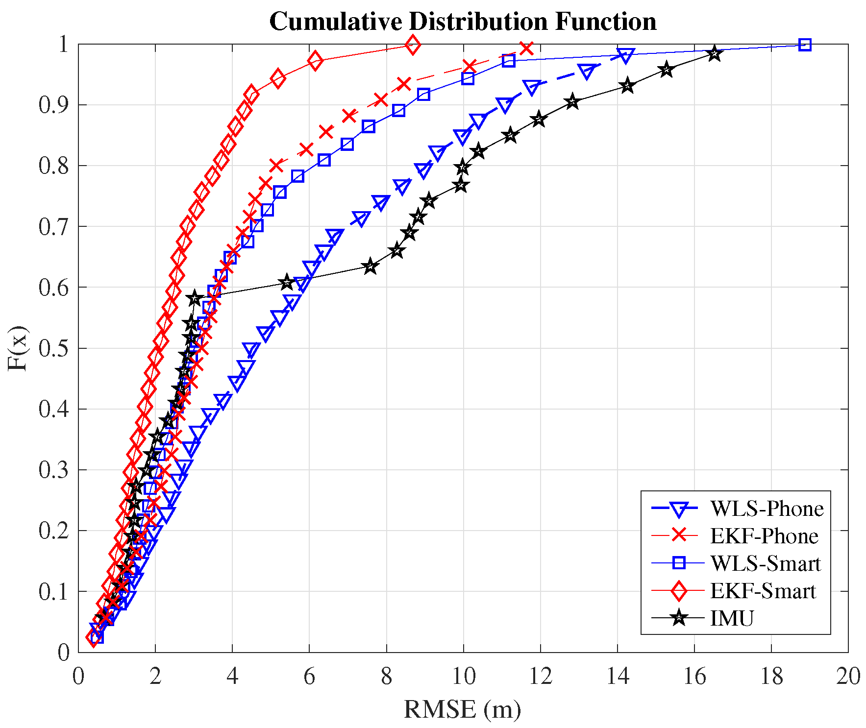
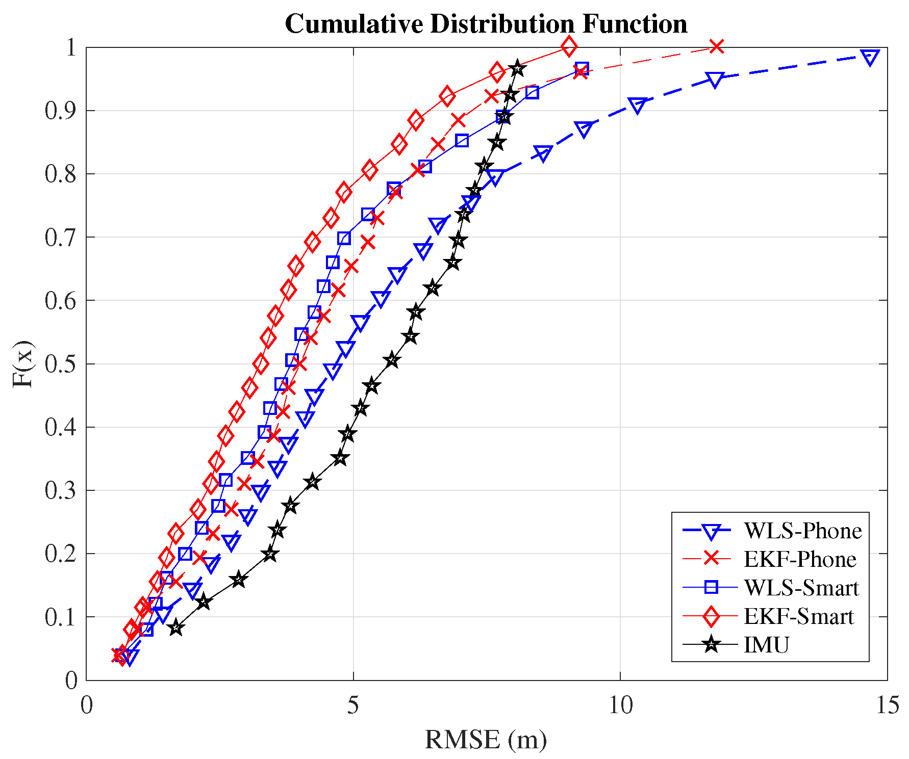
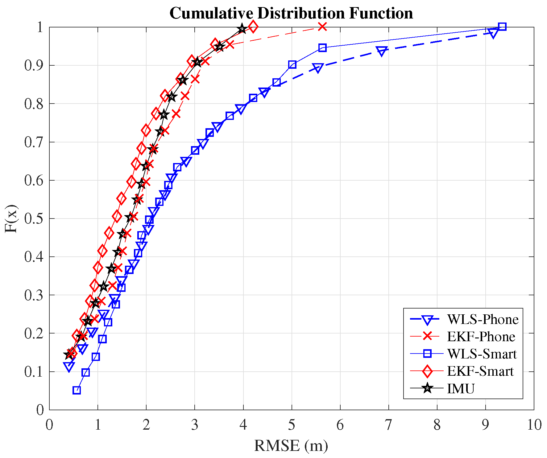
Although the typical metric for comparison between indoor positioning systems is the RMSE, we include here also the cumulative distribution function (CDF) because it provides additional information. In order to compare the positioning systems employed in this work, we will consider the value of the RMSE when the CDF equals 0.9. This means that the error committed by the algorithm is below this threshold value in 90% of the cases.
Table 2 summarizes the 90 percentiles of the validated systems. The complete CDFs are shown in
Figure 8 for the case of Path 1,
Figure 9 for the case of Path 2 and
Figure 10 for Path 3. From the figures, we can observe how the EKF-smart outperforms all of the other systems. It can also be observed how the error committed by our system is almost always below
,
and
, which can be considered a good accuracy taking into account the area of the scenario, which is
. If we compare the accuracy of our system with other indoor positioning systems based on smartphones, we can see that our system outperforms similar systems based on hybrid measurements [
25,
26,
28] and obtains accuracies similar to the ones obtained by hybrid systems that include additional map information for the sensor fusion [
31,
32,
33].
The experimental validation shows the benefits of introducing a smartwatch in an indoor positioning system based on a smartphone. The positioning accuracy obtained from the RSS measurements of the WiFi network is increased, and therefore, the overall solution including also the inertial measurements shows better performance. In fact, in the scenarios tested, the increment in accuracy from the initial PDR algorithm to the EKF-smart methods goes from 12.5% up to 56%. Furthermore, the system has been designed for being used in conjunction with a third party WiFi network, and the experimental validation has proven the adaptability of our system and its ability to obtain accurate position estimations.


 ,
, 


