
Stretchable Complementary Split Ring Resonator (CSRR)-Based Radio Frequency (RF) Sensor for Strain Direction and Level Detection


Abstract
:1. Introduction
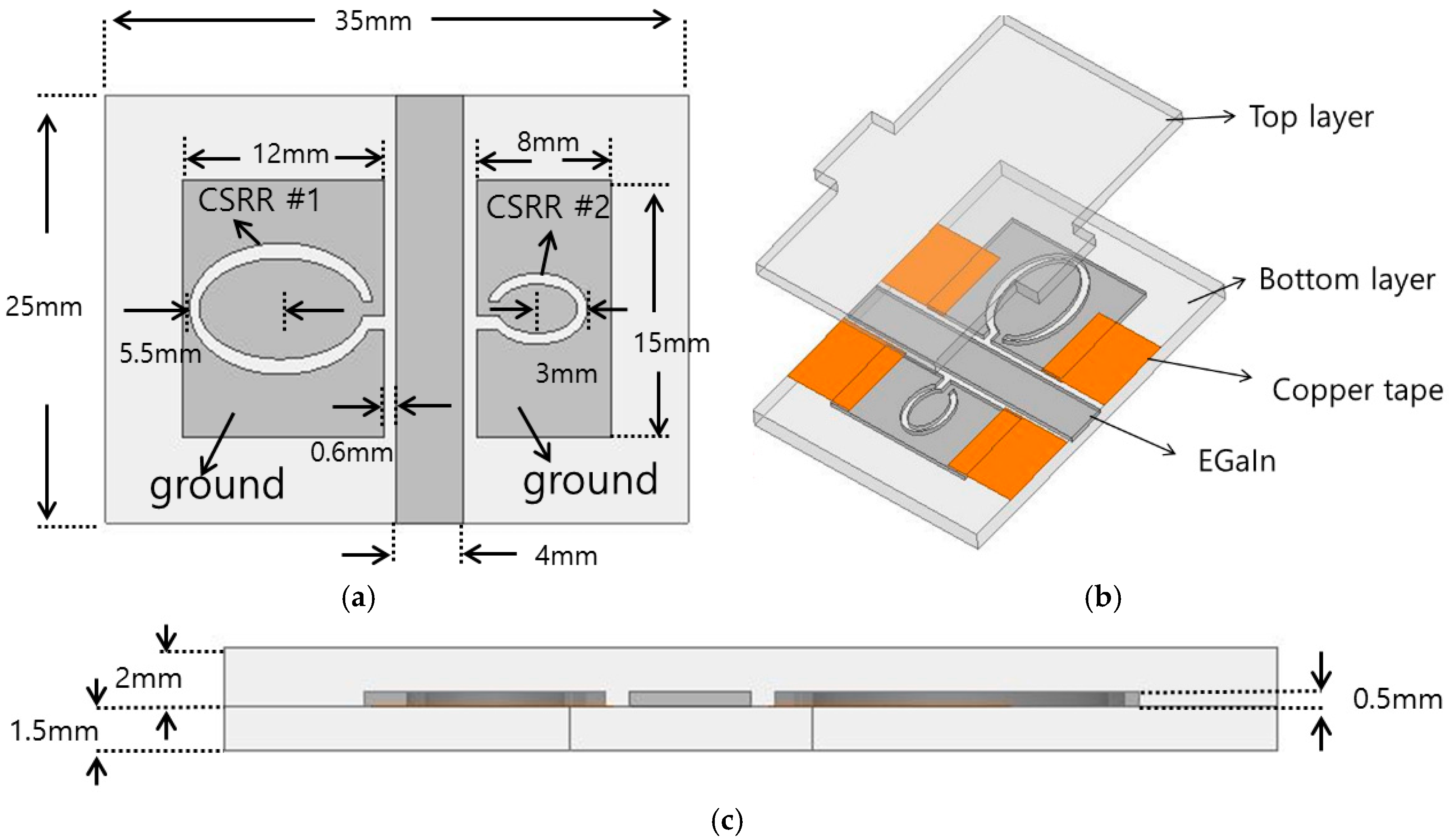
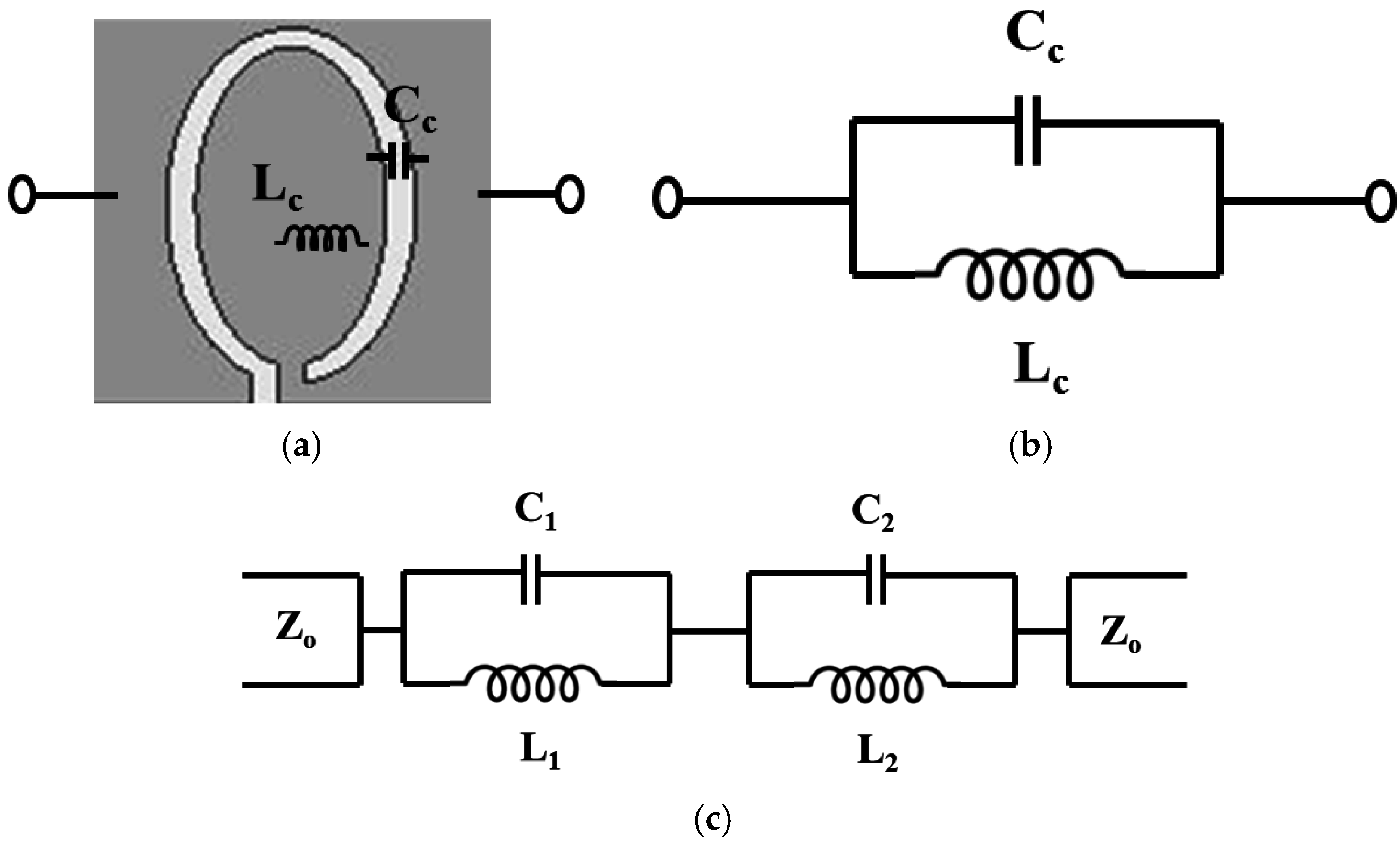
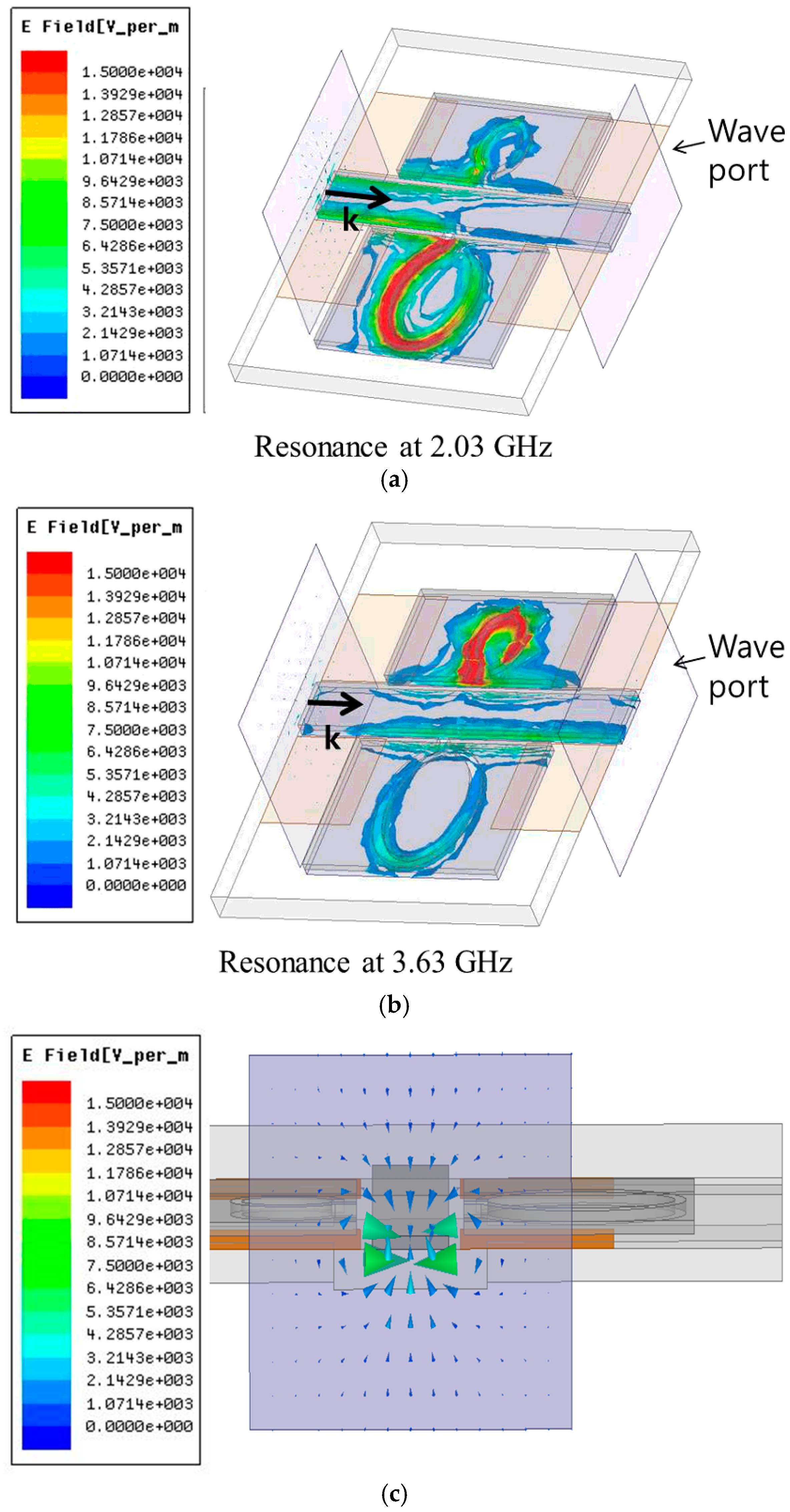
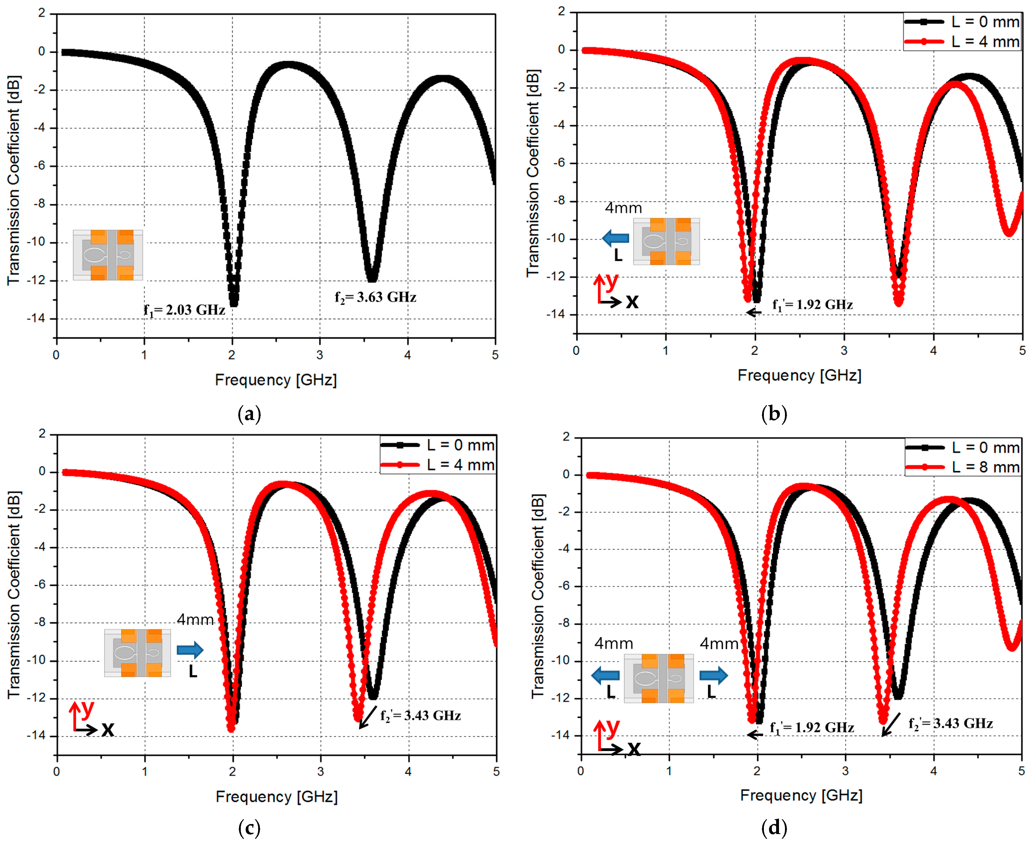
2. Operating Principle and Design
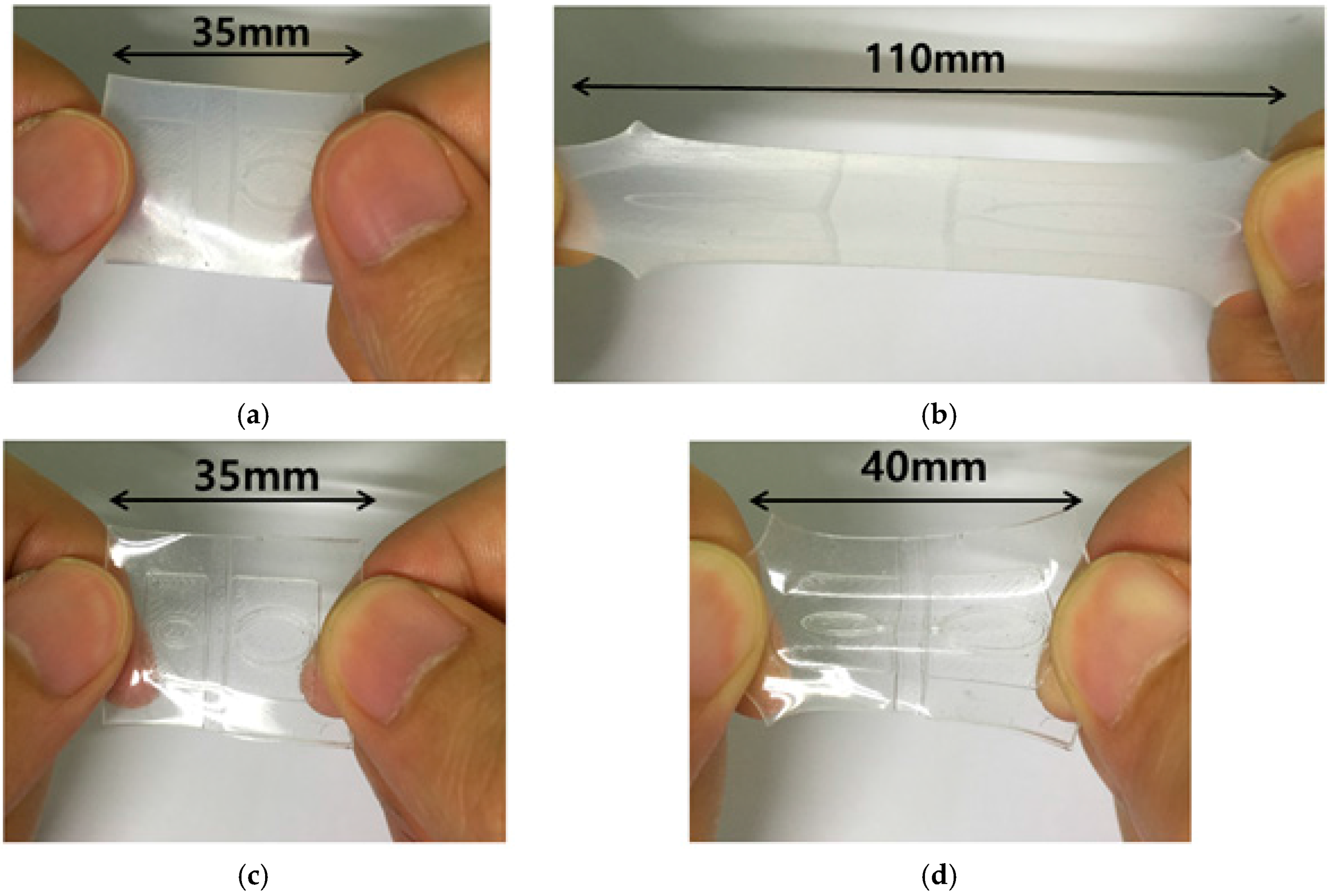
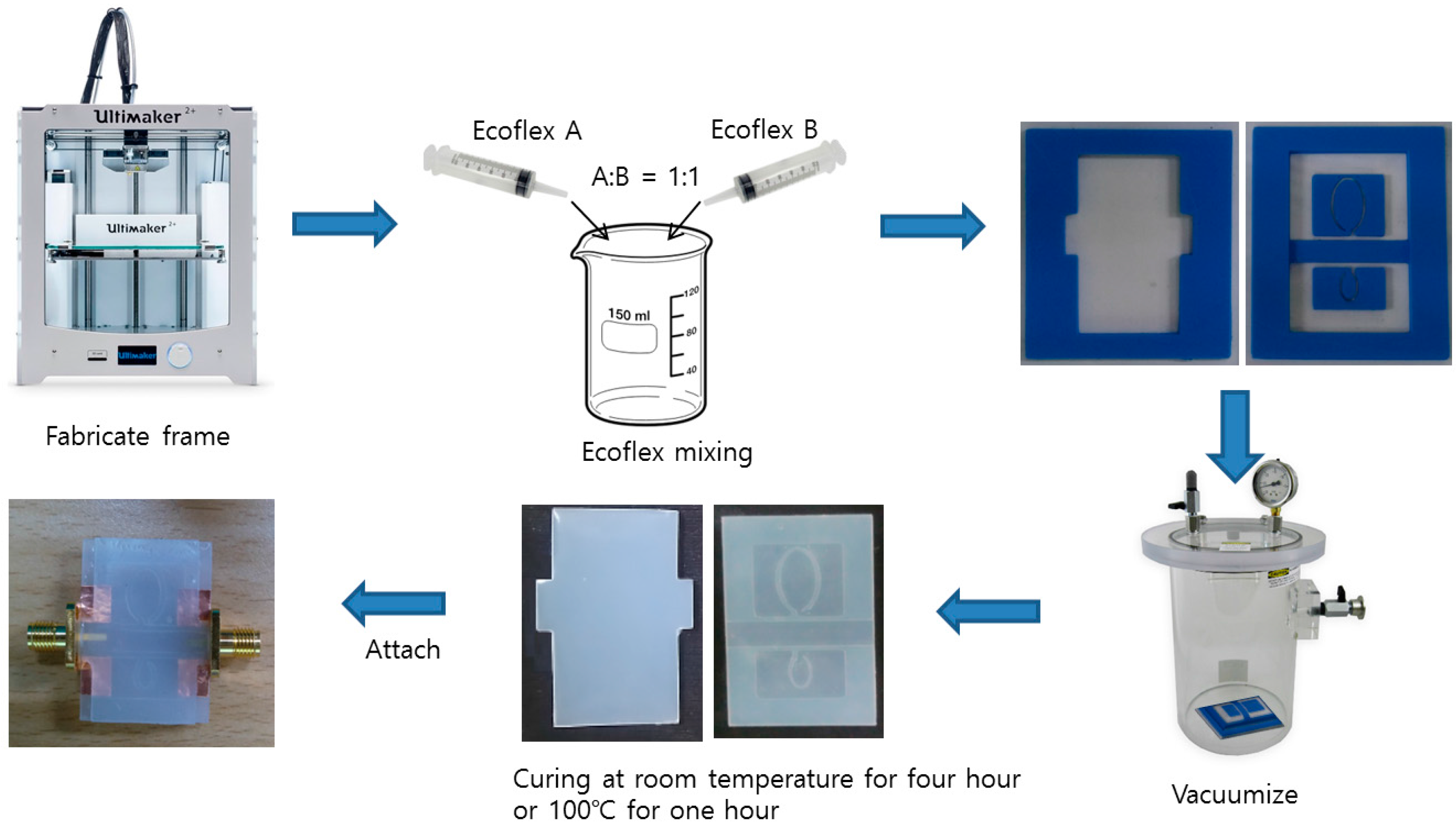
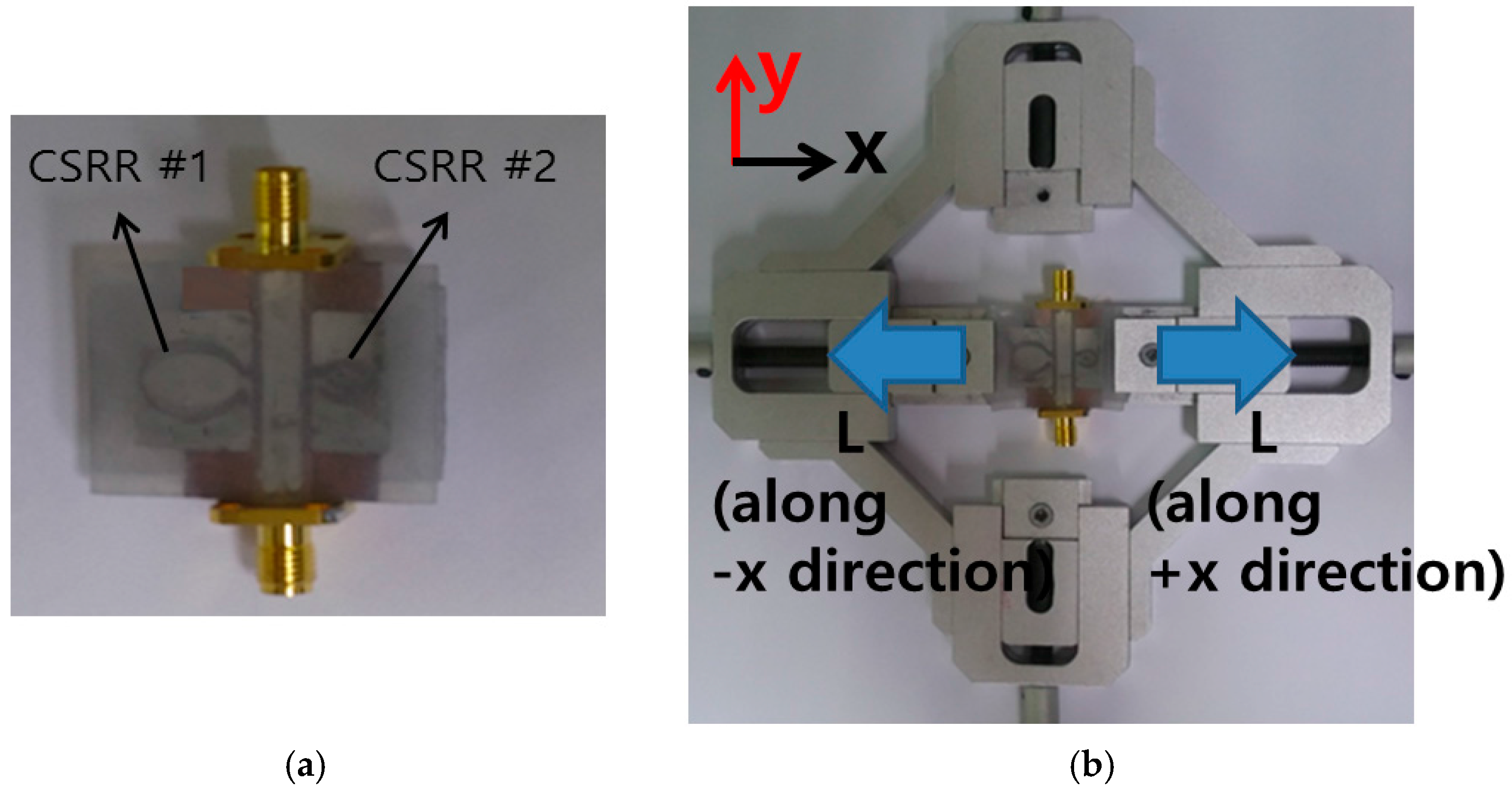
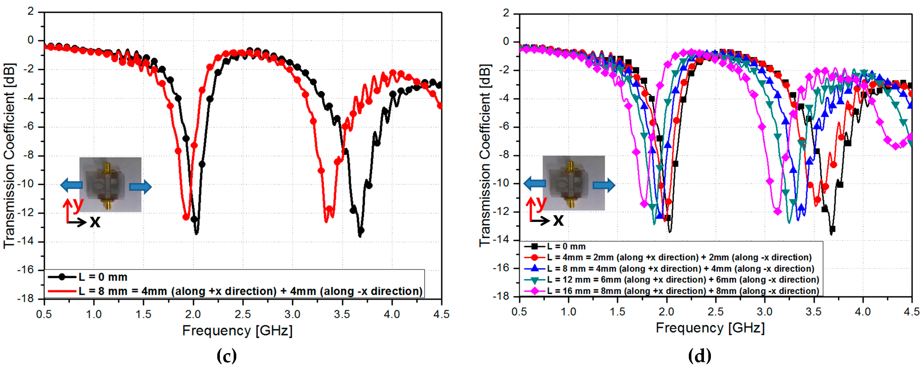
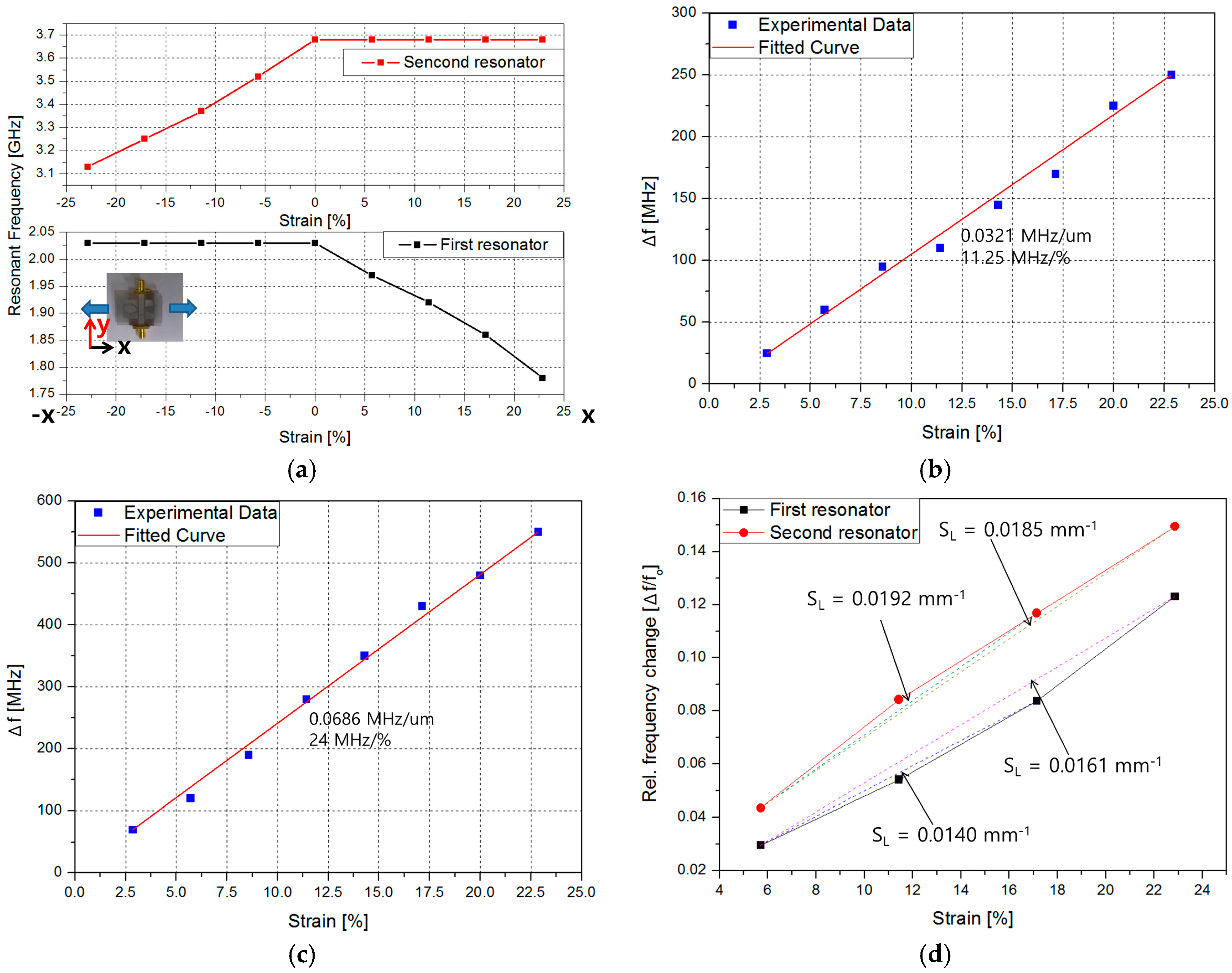
3. Fabrications and Measurement Results
4. Conclusions
Acknowledgments
Author Contributions
Conflicts of Interest
References
- Yu, C.; Wang, Z.; Yu, H.; Jiang, H.; Yu, C.; Wang, Z.; Yu, H.; Jiang, H. A stretchable temperature sensor based on elastically buckled thin film devices on elastomeric substrates. Appl. Phys. Lett. 2013, 141912, 2007–2010. [Google Scholar] [CrossRef]
- Mascaro, D.J.; Mascaro, S.A. Stretchable Fingernail Sensors for Measurement of Fingertip Force. In Proceedings of the 3rd Joint EuroHaptics Conference and Symposium on Haptic Interfaces for Virtual Environment and Teleoperator Systems, World Haptics 2009, Salt Lake City, UT, USA, 18–20 March 2009; pp. 625–626.
- Cotton, D.P.J.; Graz, I.M.; Lacour, S.P. A multifunctional capacitive sensor for stretchable electronic skins. IEEE Sens. J. 2009, 9, 2008–2009. [Google Scholar] [CrossRef]
- Amjadi, M.; Pichitpajongkit, A.; Lee, S.; Ryu, S.; Park, I. Highly stretchable and sensitive strain sensor based on silver nanowire-elastomer nanocomposite. ACS Nano 2014, 8, 5154–5163. [Google Scholar] [CrossRef] [PubMed]
- Yamada, T.; Hayamizu, Y.; Yamamoto, Y.; Yomogida, Y.; Izadi-Najafabadi, A.; Futaba, D.N.; Hata, K. A stretchable carbon nanotube strain sensor for human-motion detection. Nat. Nanotechnol. 2011, 6, 296–301. [Google Scholar] [CrossRef] [PubMed]
- Cong, L.; Tan, S.; Yahiaoui, R.; Yan, F.; Zhang, W.; Singh, R. Experimental demonstration of ultrasensitive sensing with terahertz metamaterial absorbers: A comparison with the metasurfaces. Appl. Phys. Lett. 2015, 106, 031107. [Google Scholar] [CrossRef]
- Yahiaoui, R.; Strikwerda, A.; Jepsen, P. Terahertz Plasmonic Structure with Enhanced Sensing Capabilities. IEEE Sens. J. 2016, 16, 2484–2488. [Google Scholar] [CrossRef]
- So, J.-H.; Dickey, M.D. Inherently aligned microfluidic electrodes composed of liquid metal. Lab Chip 2011, 11, 905–911. [Google Scholar] [CrossRef] [PubMed]
- Noda, K.; Iwase, E.; Matsumoto, K.; Shimoyama, I. Stretchable liquid tactile sensor for robot-joints. In Proceedings of the 2010 IEEE International Conference on Robotics and Automation, Anchorage, AK, USA, 3–7 May 2010; pp. 4212–4217.
- Li, X.; Abe, T.; Esashi, M. Deep reactive ion etching of Pyrex glass using SF6 plasma. Sens. Actuators A Phys. 2001, 87, 139–145. [Google Scholar] [CrossRef]
- So, J.H.; Thelen, J.; Qusba, A.; Hayes, G.J.; Lazzi, G.; Dickey, M.D. Reversibly deformable and mechanically tunable fluidic antennas. Adv. Funct. Mater. 2009, 19, 3632–3637. [Google Scholar] [CrossRef]
- Allen, P.B.; Chiu, D.T. Calcium-assisted glass-to-glass bonding for fabrication of glass microfluidic devices. Anal. Chem. 2008, 80, 7153–7157. [Google Scholar] [CrossRef] [PubMed]
- Chang-Yen, D.A.; Myszka, D.G.; Gale, B.K. A Novel PDMS Microfluidic Spotter for Fabrication of Protein Chips and Microarrays. J. Microelectromech. Syst. 2006, 15, 1145–1151. [Google Scholar] [CrossRef]
- Yahiaoui, R.; Tan, S.; Cong, L.; Singh, R.; Yan, F.; Zhang, W. Multispectral terahertz sensing with highly flexible ultrathin metamaterial absorber. J. Appl. Phys. 2015, 118, 083103. [Google Scholar] [CrossRef]
- Isiksacan, Z.; Guler, M.T.; Aydogdu, B.; Bilican, I.; Elbuken, C. 2016 Rapid fabrication of microfluidic PDMS devices from reusable PDMS molds using laser ablation. J. Micromech. Microeng. 2016, 26, 035008. [Google Scholar] [CrossRef]
- Liu, K.; Xiang, J.; Ai, Z.; Zhang, S.; Fang, Y.; Chen, T. PMMA microfluidic chip fabrication using laser ablation and low temperature bonding with OCA film and LOCA. Microsyst. Technol. 2016. [Google Scholar] [CrossRef]
- Kamei, K.; Mashimo, Y.; Koyama, Y.; Fockenberg, C.; Nakashima, M.; Nakajima, M.; Li, J.; Chen, Y. 3D printing of soft lithography mold for rapid production of polydimethylsiloxane-based microfluidic devices for cell stimulation with concentration gradients. Biomed. Microdevices 2015, 17, 1–8. [Google Scholar] [CrossRef] [PubMed]
- Chan, H.N.; Chen, Y.; Shu, Y.; Chen, Y.; Tian, Q.; Wu, H. Direct, one-step molding of 3D-printed structures for convenient fabrication of truly 3D PDMS microfluidic chips. Microfluid. Nanofluid. 2015, 19, 9–18. [Google Scholar] [CrossRef]
- Kubo, M.; Li, X.; Kim, C.; Hashimoto, M.; Wiley, B.J.; Ham, D.; Whitesides, G.M. Stretchable microfluidic radiofrequency antennas. Adv. Mater. 2010, 22, 2749–2752. [Google Scholar] [CrossRef] [PubMed]
- Lee, P.; Lee, J.; Lee, H.; Yeo, J.; Hong, S.; Nam, K.H.; Lee, D.; Lee, S.S.; Ko, S.H. Highly stretchable and highly conductive metal electrode by very long metal nanowire percolation network. Adv. Mater. 2012, 24, 3326–3332. [Google Scholar] [CrossRef] [PubMed]
- Yoon, S.G.; Koo, H.J.; Chang, S.T. Highly Stretchable and Transparent Microfluidic Strain Sensors for Monitoring Human Body Motions. ACS Appl. Mater. Interfaces 2015, 7, 27562–27570. [Google Scholar] [CrossRef] [PubMed]
- Hayes, G.J.; So, J.-H.; Qusba, A.; Dickey, M.D.; Lazzi, G. Flexible Liquid Metal Alloy (EGaIn) Microstrip Patch Antenna. IEEE Trans. Antennas Propag. 2012, 60, 2151–2156. [Google Scholar] [CrossRef]
- Yoon, J.; Hong, S.Y.; Lim, Y.; Lee, S.J.; Zi, G.; Ha, J.S. Design and fabrication of novel stretchable device arrays on a deformable polymer substrate with embedded liquid-metal interconnections. Adv. Mater. 2014, 26, 6580–6586. [Google Scholar] [CrossRef] [PubMed]
- Li, G.; Wu, X.; Lee, D.-W. Selectively Plated Stretchable Liquid Metal Wires for Transparent Electronics. Sens. Actuators B Chem. 2015, 221, 1114–1119. [Google Scholar] [CrossRef]
- Reddy, N.; Raghava, S. Split ring resonator and its evolved structures over the past decade. Int. Conf. Emerg. Trends Comput. C. Nanotechnol. 2013, 625, 25–26. [Google Scholar]
- Jeon, D.; Lee, B. Simplified modeling of ring resonators and split ring resonators using magnetization. J. Electromagn. Eng. Sci. 2013, 13, 134–136. [Google Scholar] [CrossRef]
- Velez, A.; Aznar, F.; Bonache, J.; Velazquez-Ahumada, M.C.; Martel, J.; Martin, F. Open Complementary Split Ring Resonators (OCSRRs) and their application to wideband cpw band pass filters. IEEE Microw. Wirel. Compon. Lett. 2009, 19, 197–199. [Google Scholar] [CrossRef]
- Baena, J.D.; Bonache, J.; Martin, F.; Sillero, R.M.; Falcone, F.; Lopetegi, T.; Laso, M.A.G.; Garcia-Garcia, J.; Gil, I.; Portillo, M.F.; et al. Equivalent-circuit models for split-ring resonators and complementary split-ring resonators coupled to planar transmission lines. IEEE Trans. Microw. Theory Tech. 2005, 53, 1451–1460. [Google Scholar] [CrossRef]
- Melik, R.; Unal, E.; Perkgoz, N.K.; Puttlitz, C.; Demir, H.V. Flexible metamaterials for wireless strain sensing. Appl. Phys. Lett. 2009, 95, 181105. [Google Scholar] [CrossRef]
- Melik, R.; Unal, E.; Perkgoz, N.K.; Santoni, B.; Kamstock, D.; Puttlitz, C.; Demir, H.V. Nested metamaterials for wireless strain sensing. IEEE J. Sel. Top. Quantum Electron. 2010, 16, 450–458. [Google Scholar] [CrossRef]
- Li, J.; Shah, C.M.; Withayachumnankul, W.; Ung, B.S.; Mitchell, A.; Sriram, S.; Bhaskaran, M.; Chang, S.; Abbott, D. Flexible terahertz metamaterials for dual-axis strain sensing. Opt. Lett. 2013, 38, 2104–2106. [Google Scholar] [CrossRef] [PubMed]
- Qian, Z.; Tang, Q.; Li, J.; Zhao, H.; Zhang, W. Analysis and design of a strain sensor based on a microstrip patch antenna. In Proceedings of the 2012 International Conference on Microwave and Millimeter Wave Technology (ICMMT), Shenzhen, China, 5–8 May 2012; pp. 3–5.
- Thai, T.T.; Aubert, H.; Pons, P.; Dejean, G.; Mtentzeris, M.; Plana, R. Novel design of a highly sensitive RF strain transducer for passive and remote sensing in two dimensions. IEEE Trans. Microw. Theory Tech. 2013, 61, 1385–1396. [Google Scholar] [CrossRef]


| Strain (%) | CSRR #1 (GHz) | CSRR #2 (GHz) |
|---|---|---|
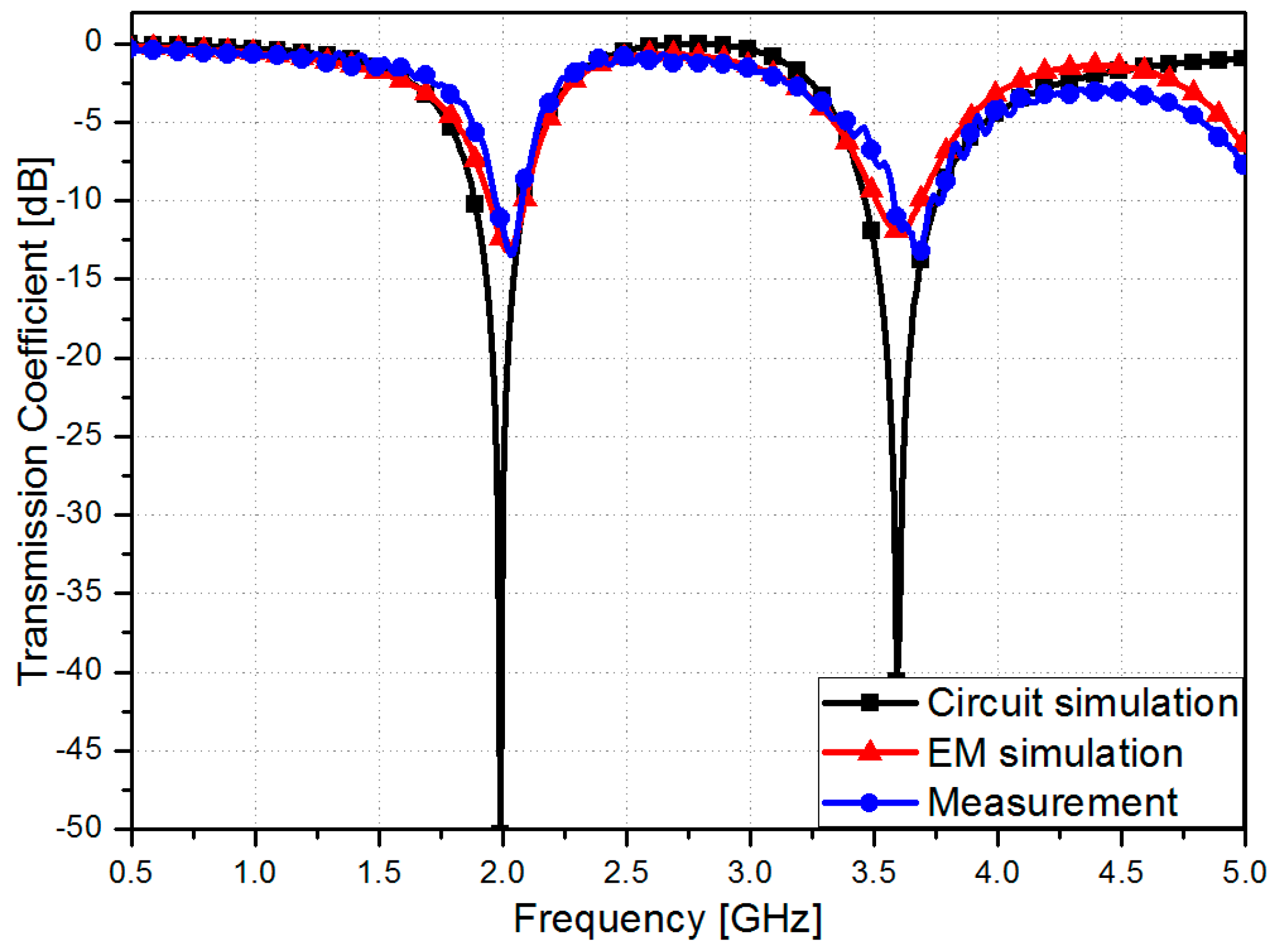
| 0 | 2.03 | 3.68 |
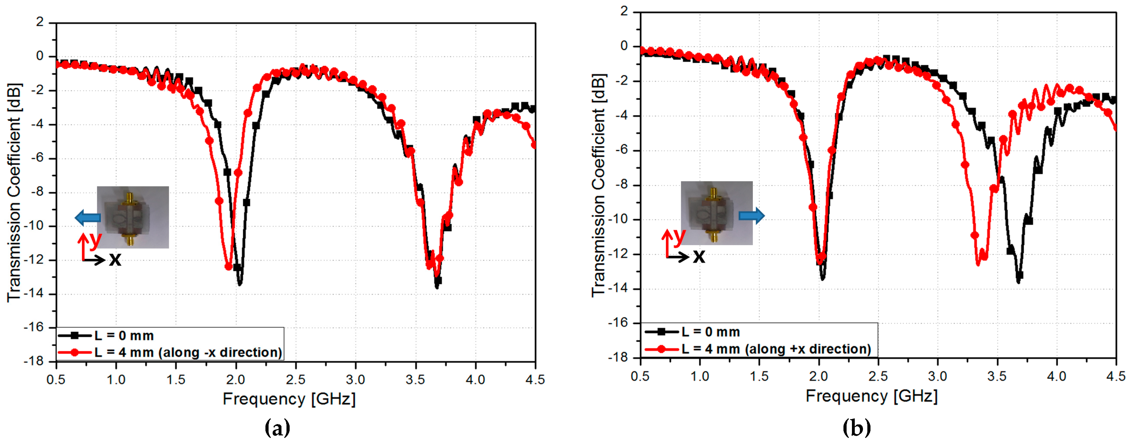
| 11.42 = 5.71 (along +x direction) + 5.71 (along −x direction) | 1.97 | 3.52 |
| 22.84 = 11.42 (along +x direction) + 11.42 (along −x direction) | 1.92 | 3.37 |
| 34.28 = 17.14 (along +x direction) + 17.14 (along −x direction) | 1.86 | 3.25 |
| 45.72 = 22.86 (along +x direction) + 22.86 (along −x direction) | 1.78 | 3.13 |
| This Work | [29] | [30] | [31] | [32] | [33] | |
|---|---|---|---|---|---|---|
| Substrate | Ecoflex | Kapton tape | Si | PDMS | RT/Duroid 5880 | Kapton |
| Conductive Material | EgaIn | Au | Au | Au | Cu | Cu/Al |
| Fabrication Method | 3D printing | Lithography, Evaporation | Lithography, Evaporation | Spin coating, Evaporation, Photolithography | Lithography | Lithography, Manual assembly |
| Maximum Strain Level (%) | 45.72 | N/A | N/A | 9.78 | 0.2 | 1 |
| Tuning Ratio (%) | 12.31, 14.95 | 5.69 | 0.21 | 5.14 | 0.14 | 2.35 |
| Number Of Detect Direction | 2 | 1 | 1 | 2 | 1 | 2 |
| Resonant Frequency (GHz) | 2.03, 3.68 | 12.3 | 0.4742 | 700 | 5 | 3.62 |
| Q factor | 4.58~4.83 | 12–18 † | N/A | 3~4 † | 40~49 † | 40~50 † |
| Resonator | Metamaterial | Metamaterial | Metamaterial | Metamaterial | Patch Antenna | Open loop |
© 2016 by the authors; licensee MDPI, Basel, Switzerland. This article is an open access article distributed under the terms and conditions of the Creative Commons Attribution (CC-BY) license (http://creativecommons.org/licenses/by/4.0/).
Share and Cite
Eom, S.; Lim, S. Stretchable Complementary Split Ring Resonator (CSRR)-Based Radio Frequency (RF) Sensor for Strain Direction and Level Detection. Sensors 2016, 16, 1667. https://doi.org/10.3390/s16101667
Eom S, Lim S. Stretchable Complementary Split Ring Resonator (CSRR)-Based Radio Frequency (RF) Sensor for Strain Direction and Level Detection. Sensors. 2016; 16(10):1667. https://doi.org/10.3390/s16101667
Chicago/Turabian StyleEom, Seunghyun, and Sungjoon Lim. 2016. "Stretchable Complementary Split Ring Resonator (CSRR)-Based Radio Frequency (RF) Sensor for Strain Direction and Level Detection" Sensors 16, no. 10: 1667. https://doi.org/10.3390/s16101667
APA StyleEom, S., & Lim, S. (2016). Stretchable Complementary Split Ring Resonator (CSRR)-Based Radio Frequency (RF) Sensor for Strain Direction and Level Detection. Sensors, 16(10), 1667. https://doi.org/10.3390/s16101667