
Design, Implementation and Validation of the Three-Wheel Holonomic Motion System of the Assistant Personal Robot (APR)

 ,
, 
Abstract
:1. Introduction
2. Background
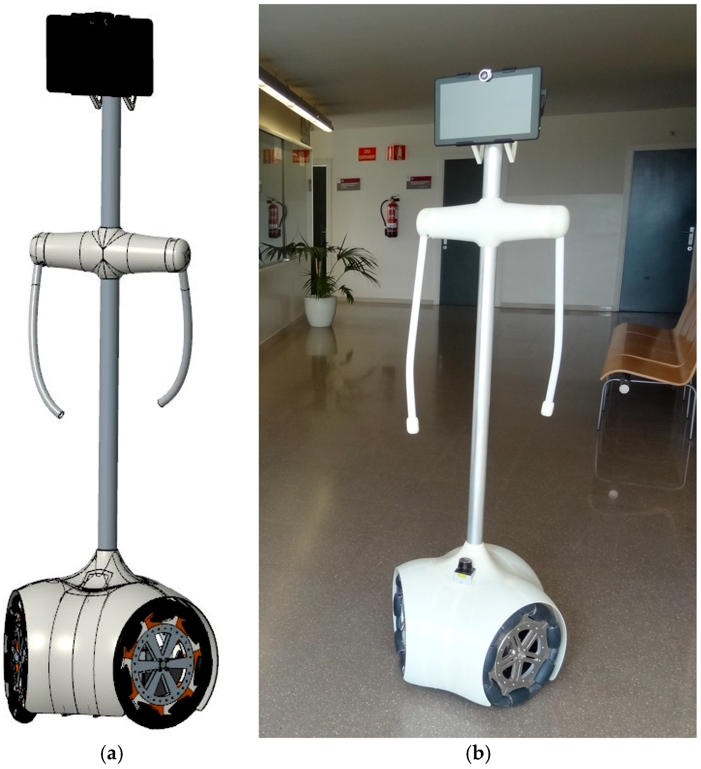
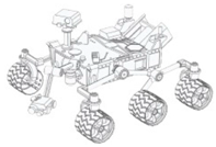
3. The Assistant Personal Robot
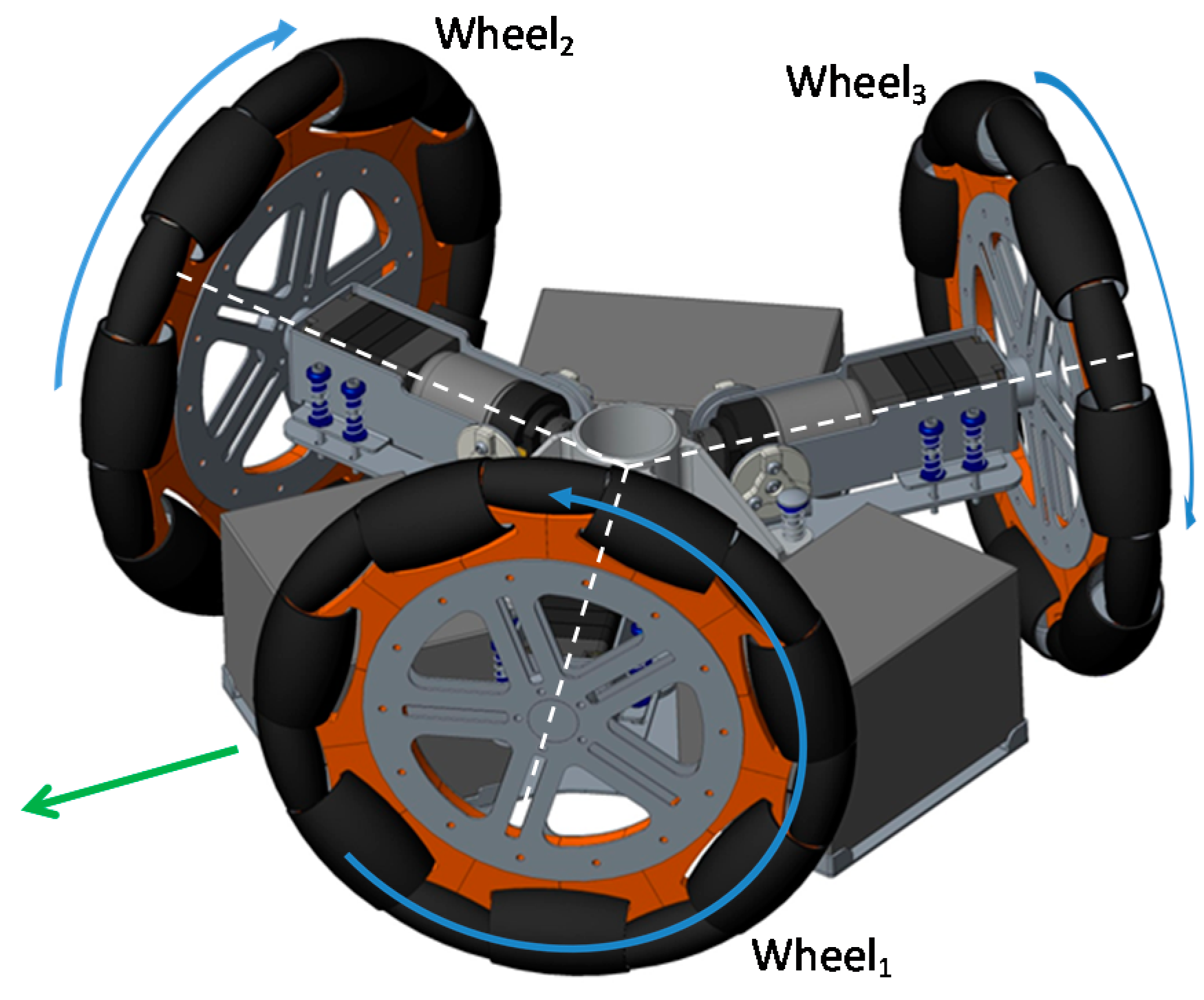
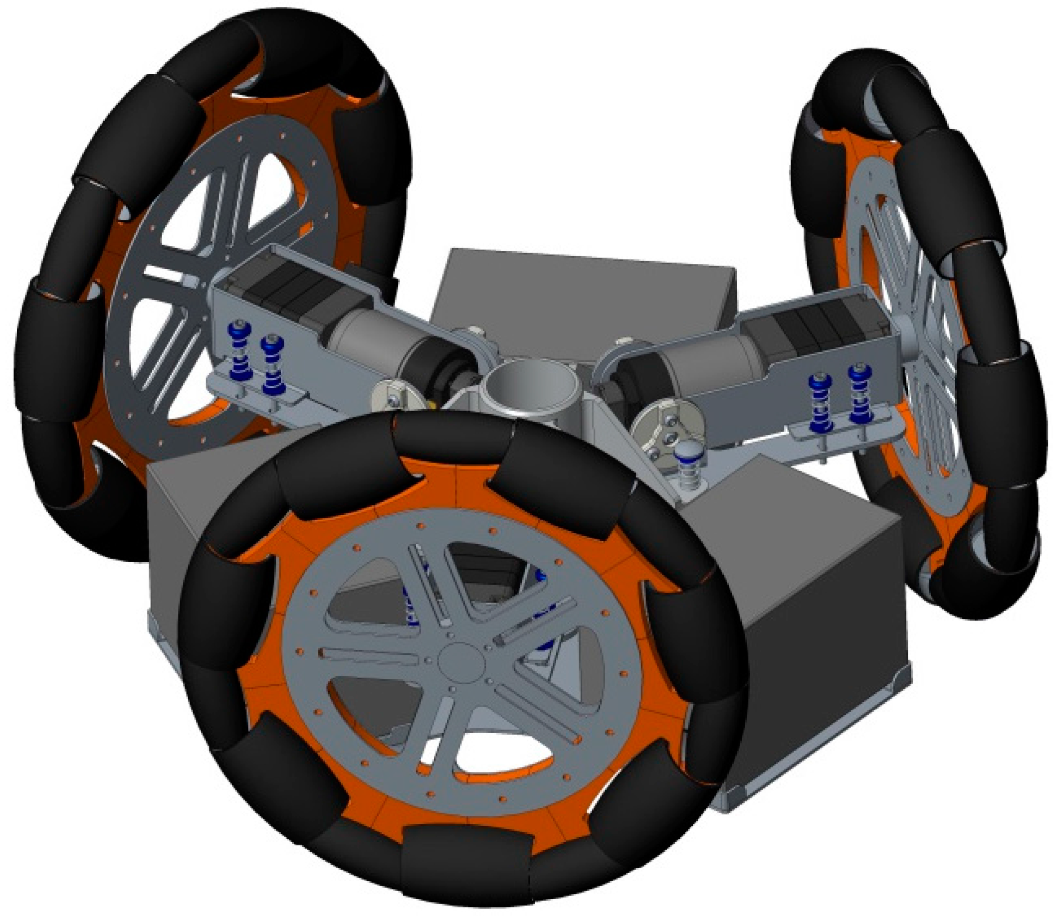
3.1. Mechanical Implementation of the Motion System of the APR
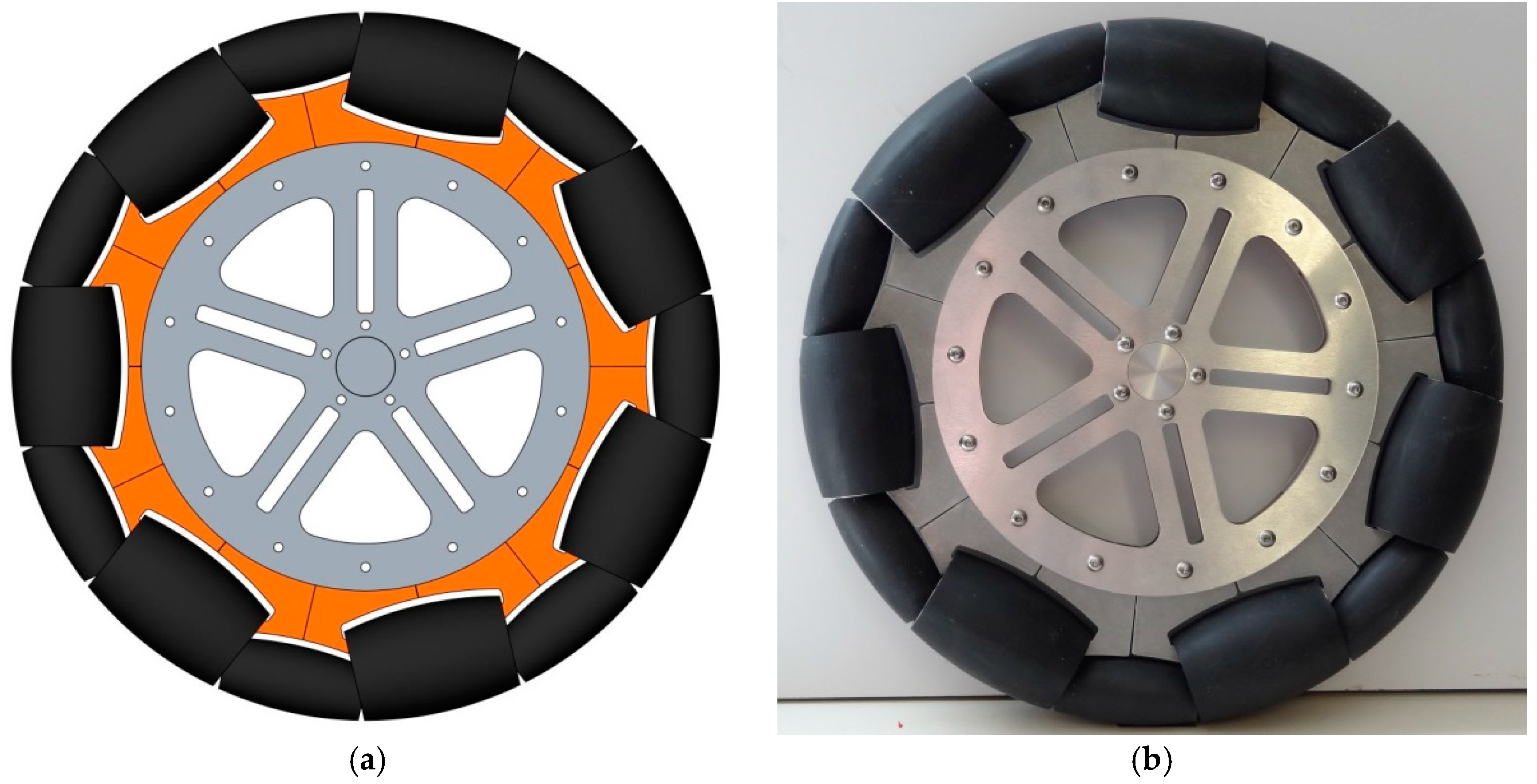
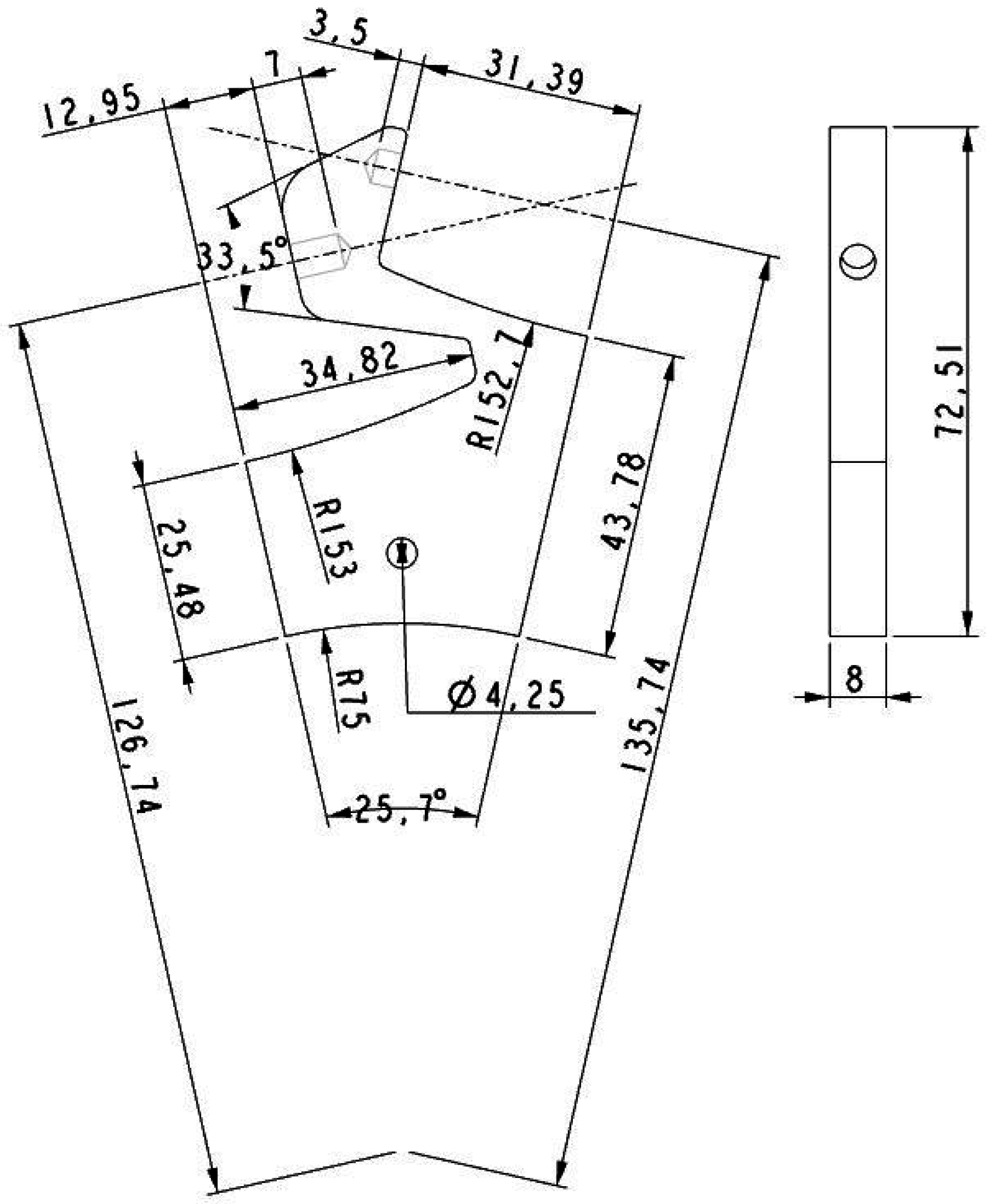
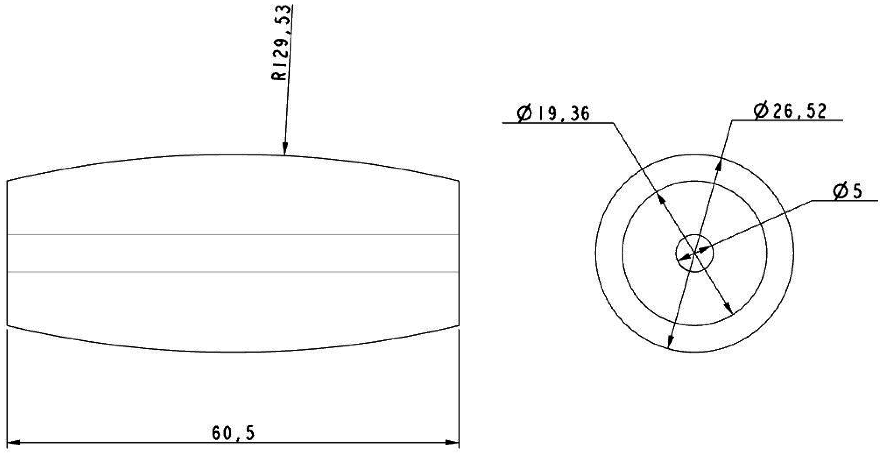
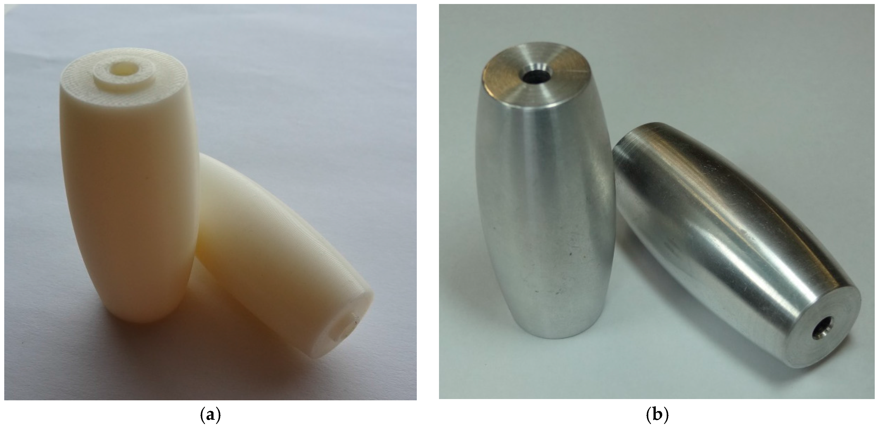
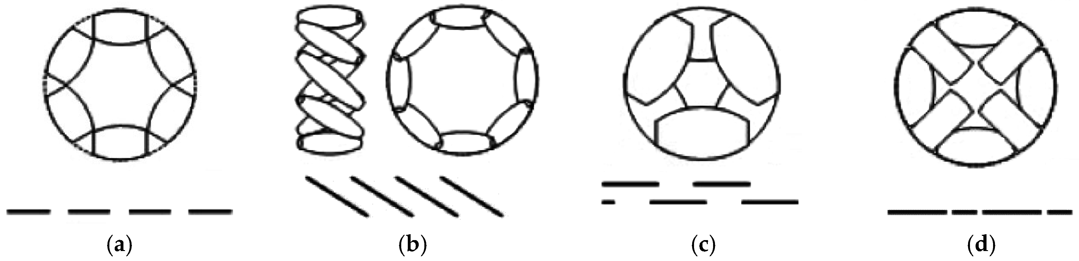
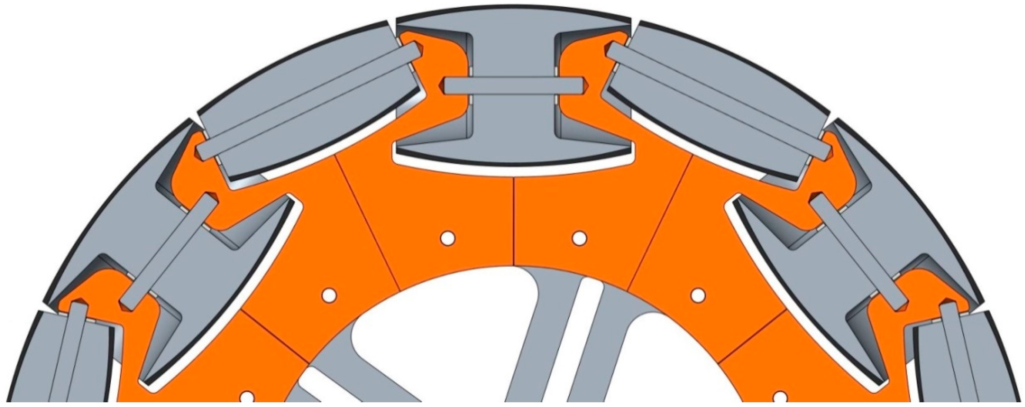
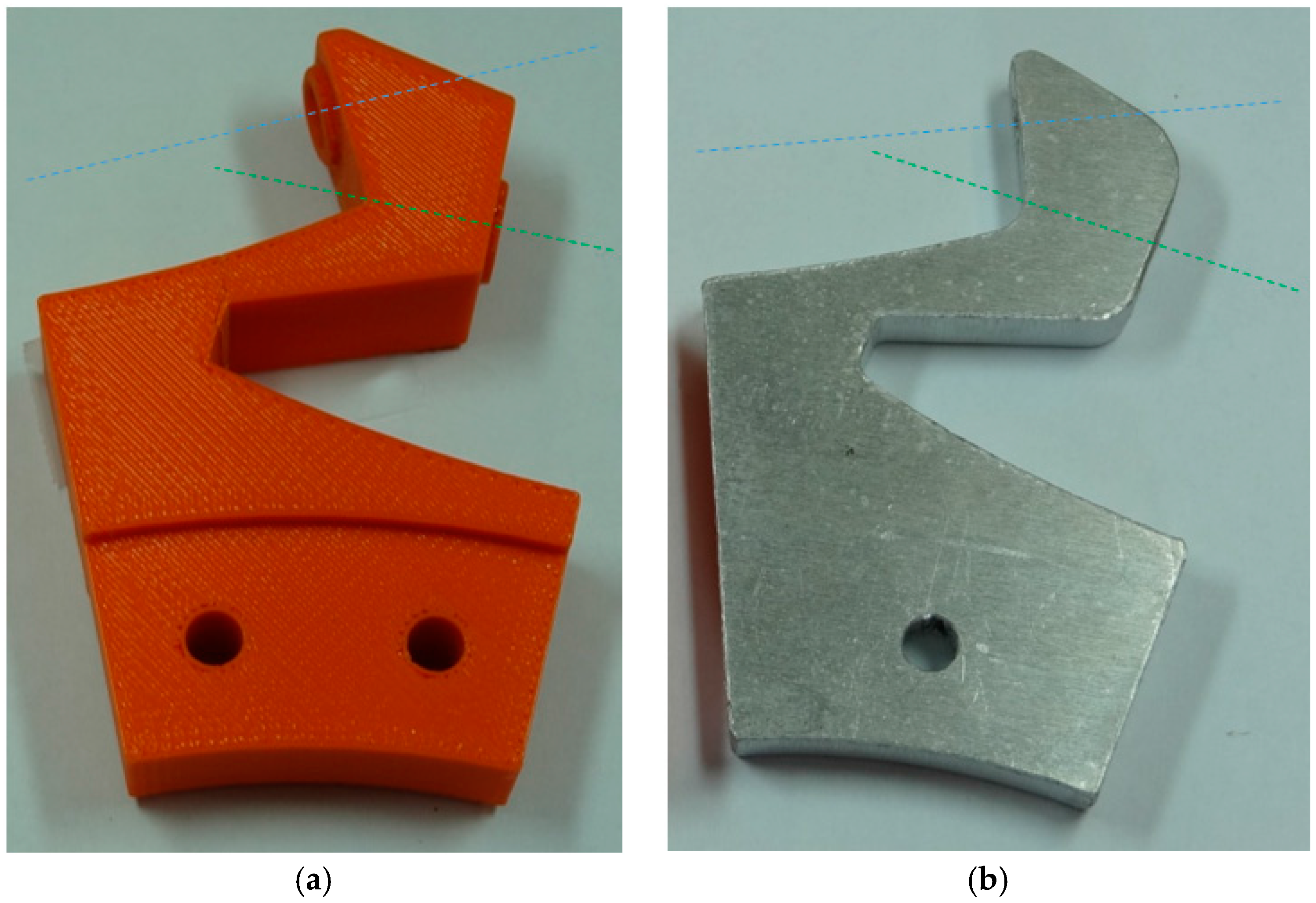
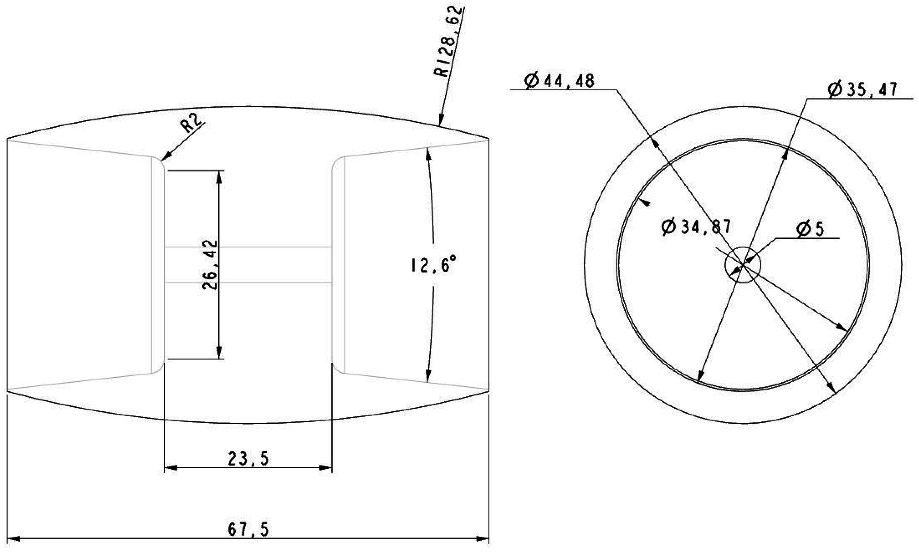
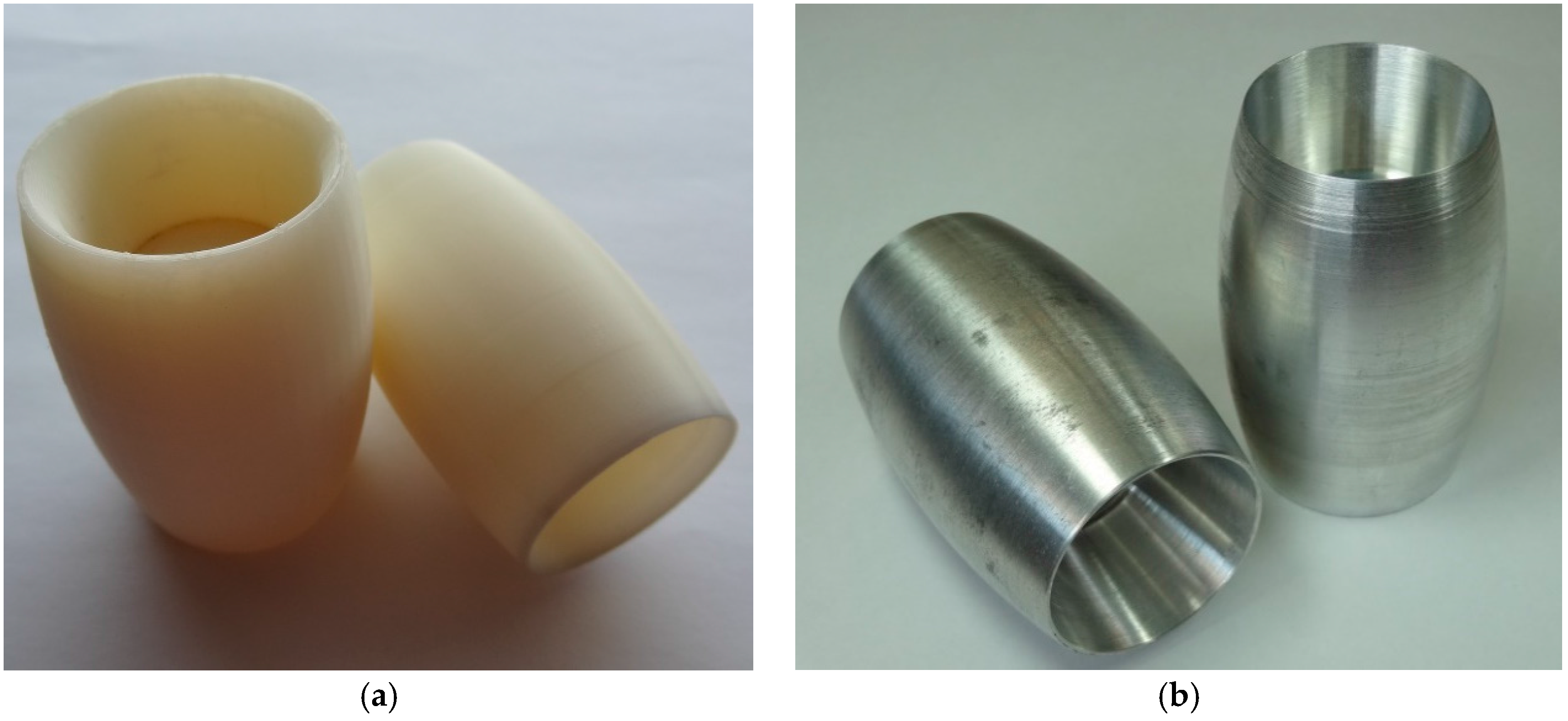
3.2. Omnidirectional Wheels
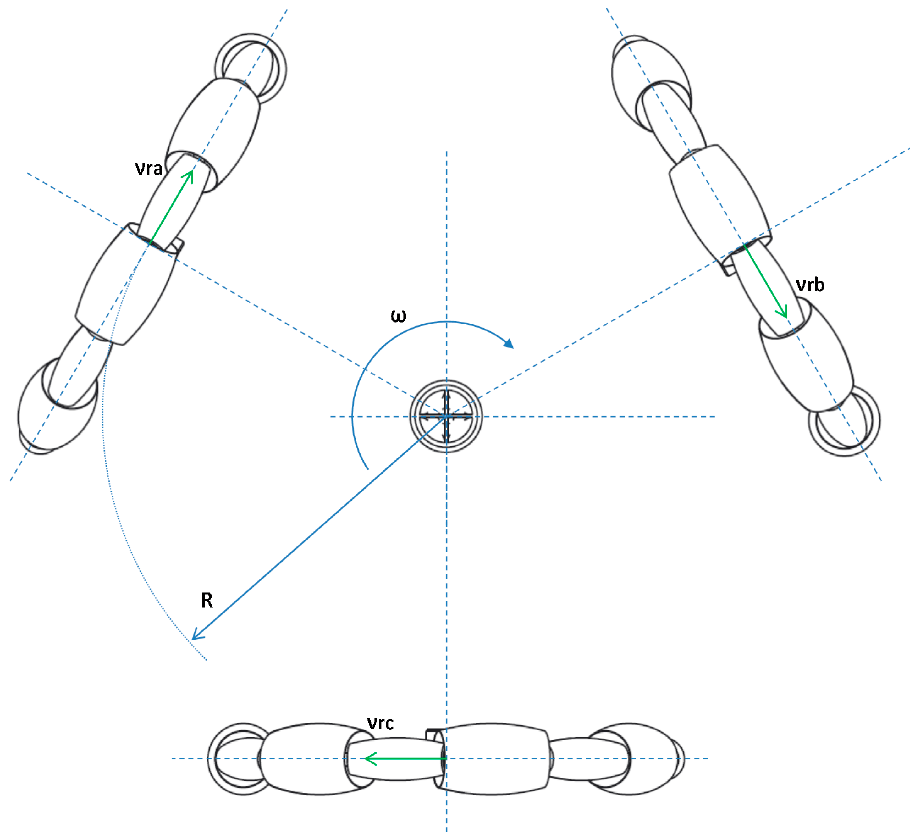
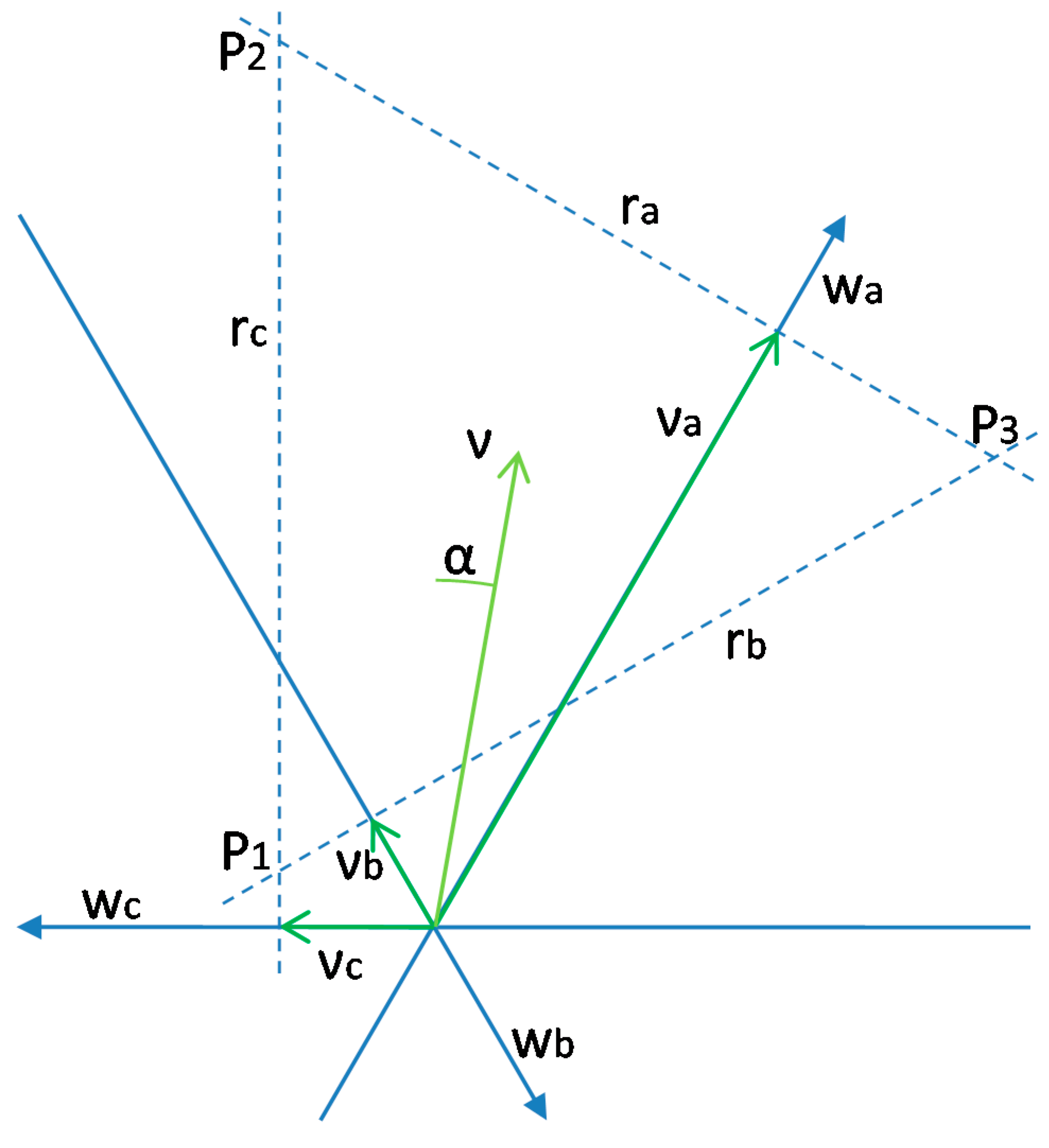
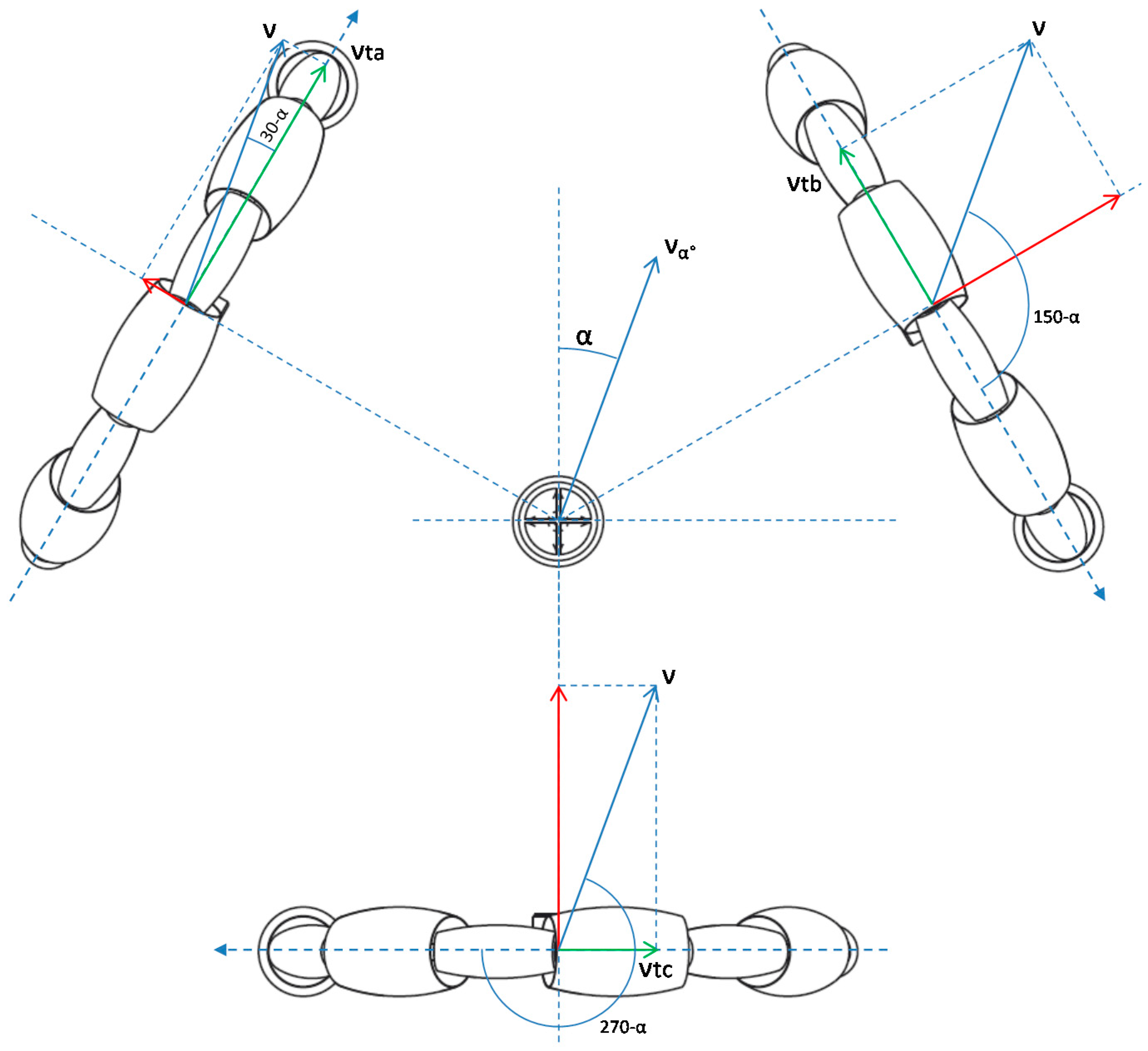
3.3. Inverse Kinematic Model
3.4. Kinematic Model
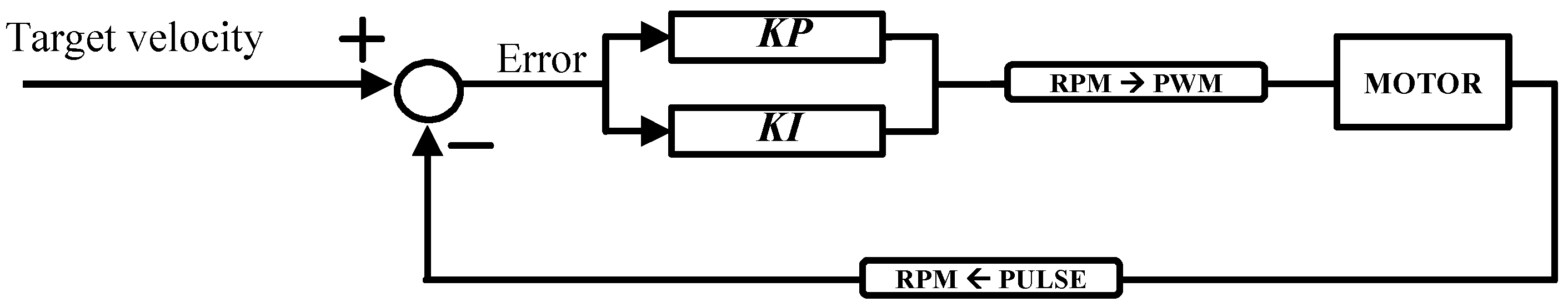
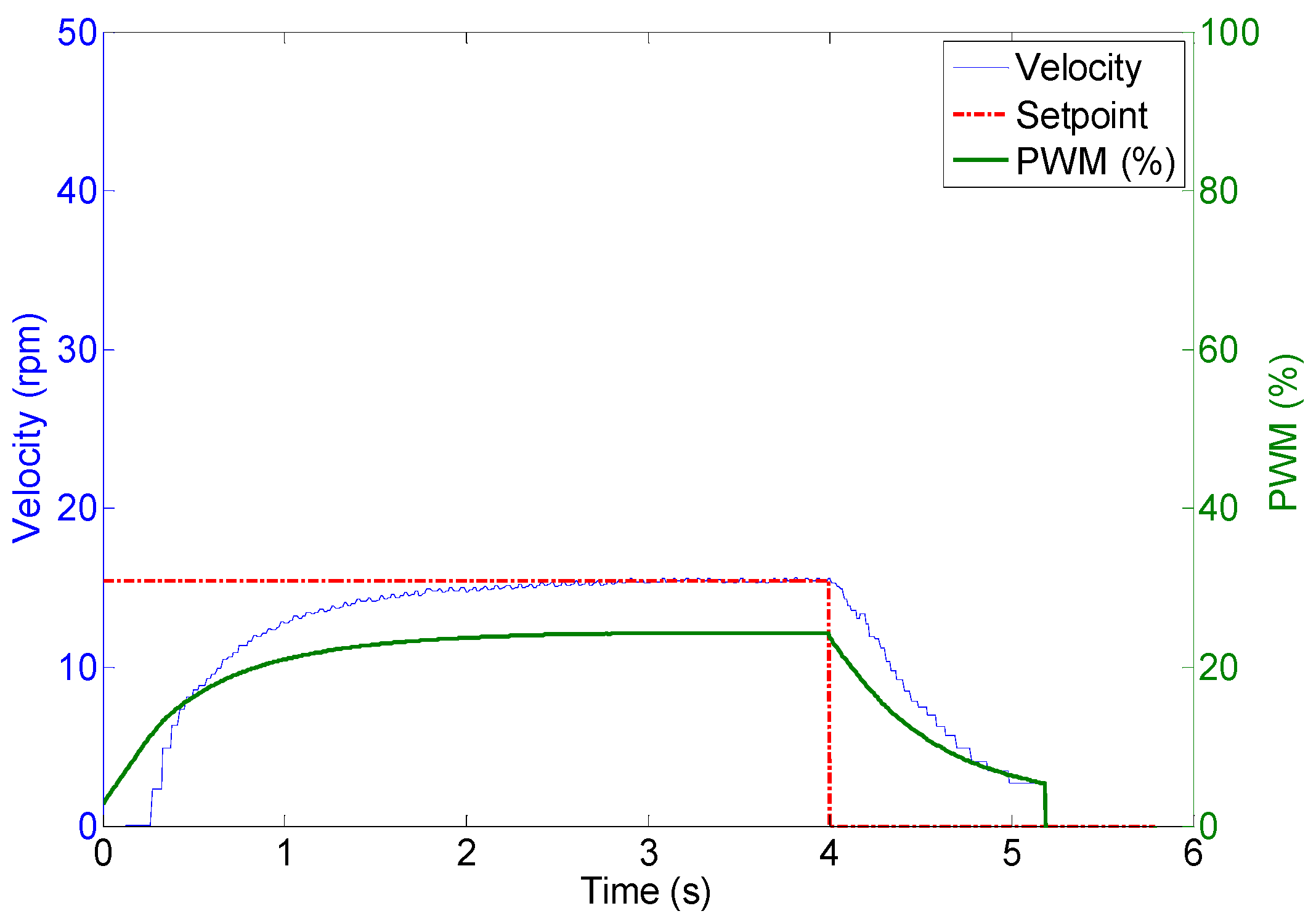
4. Control of the Motion System
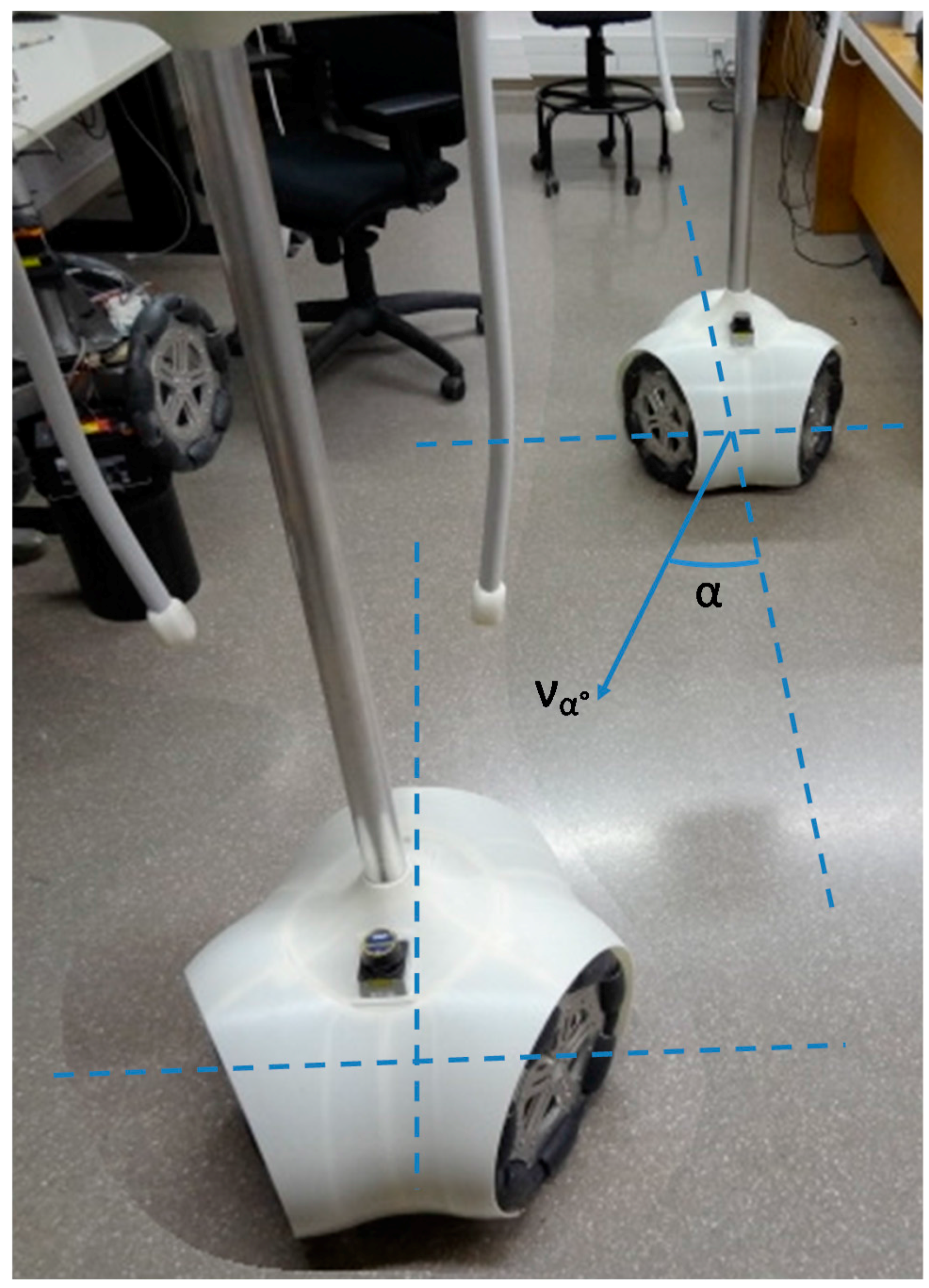
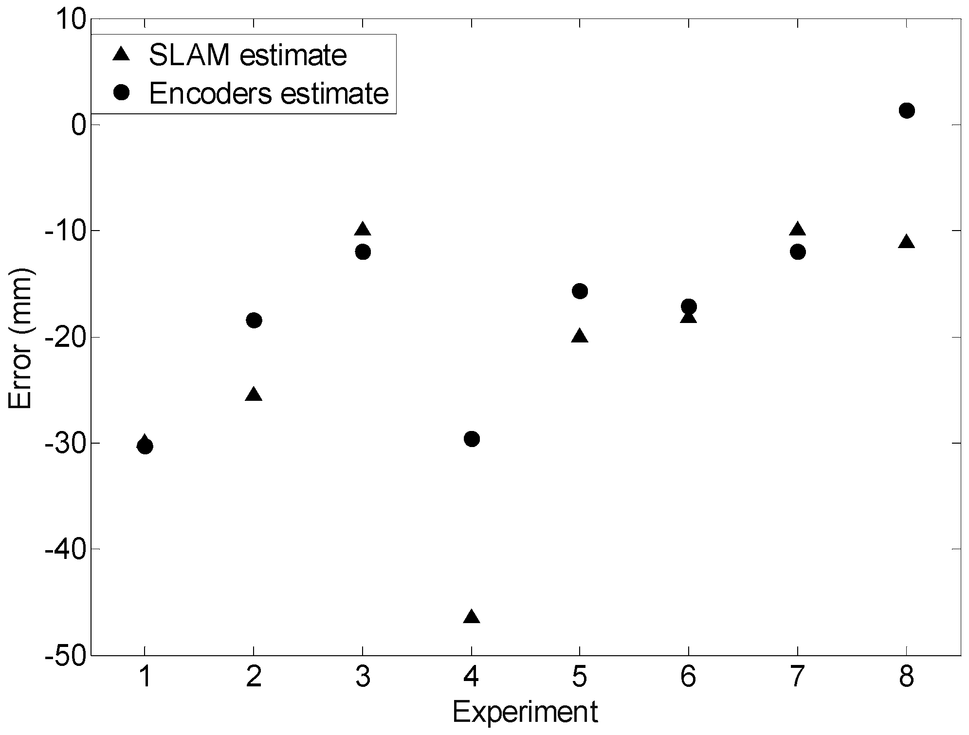
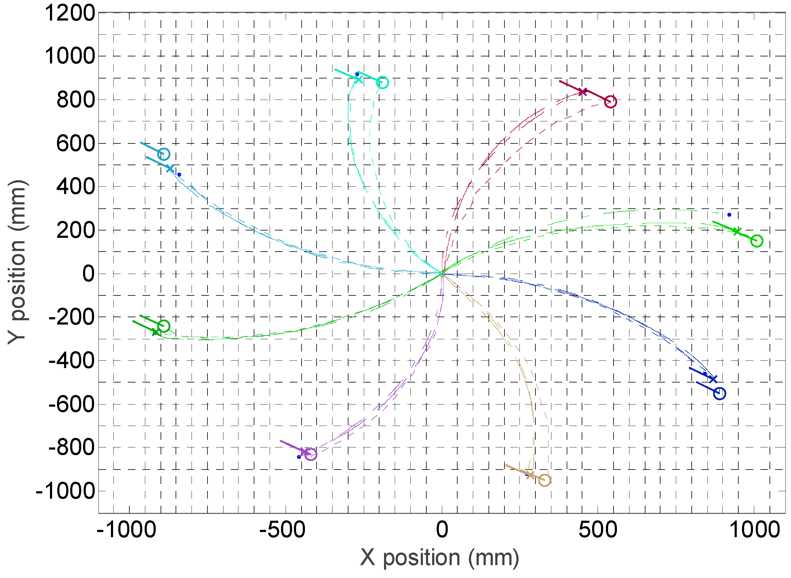
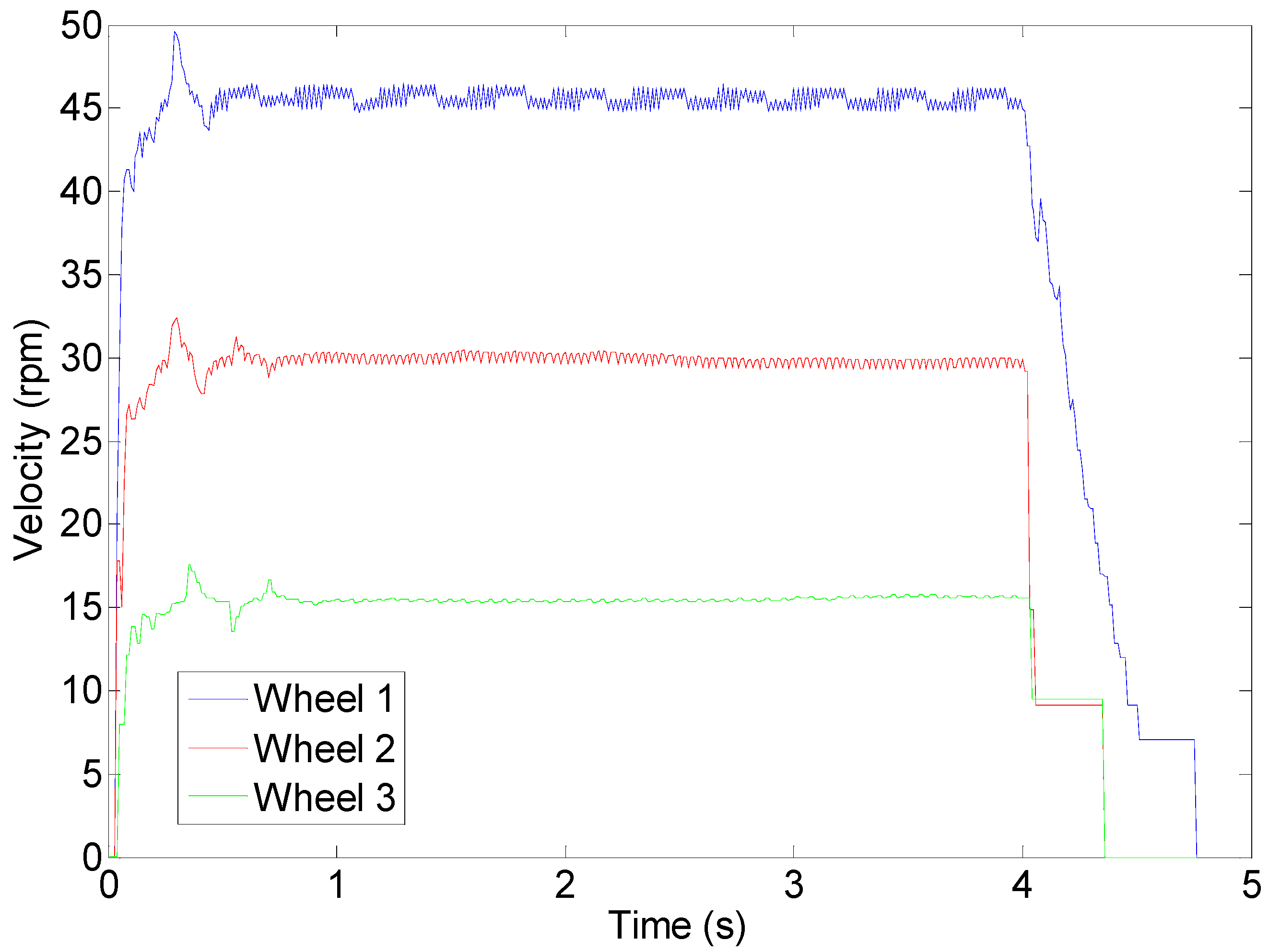
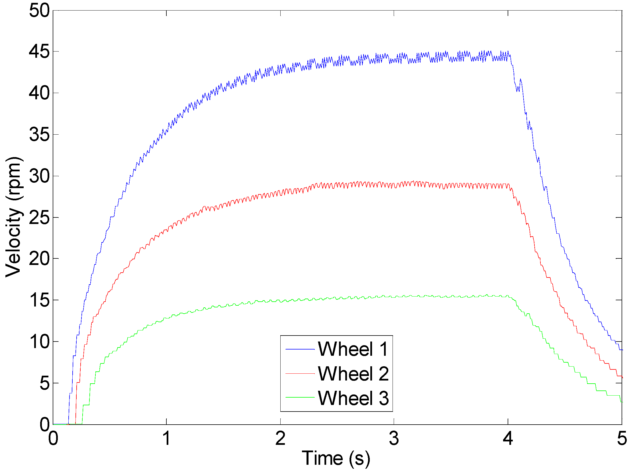
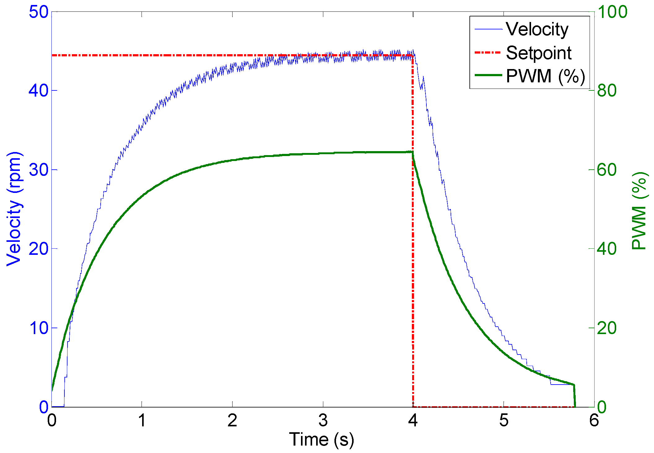
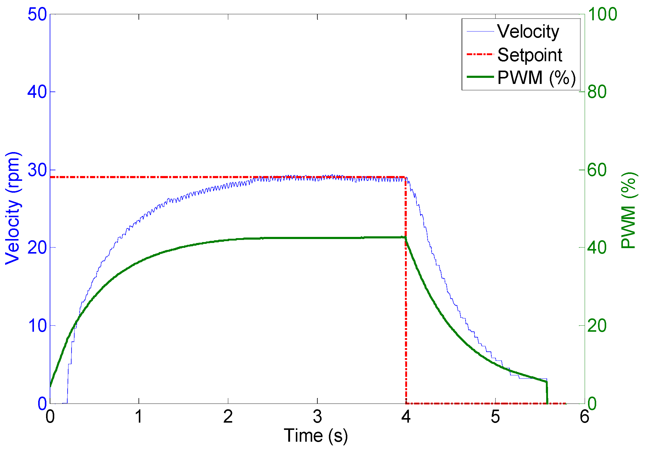
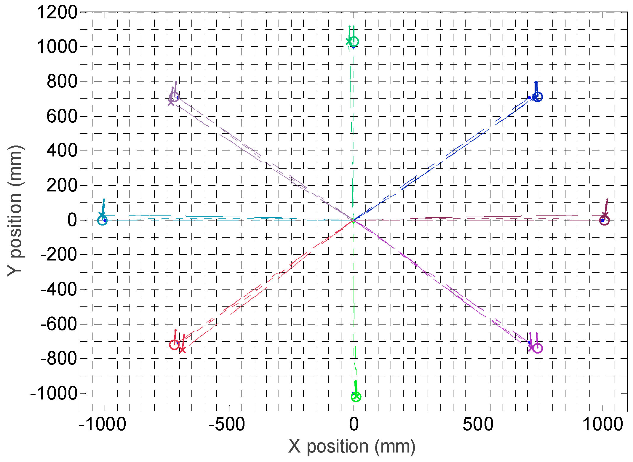
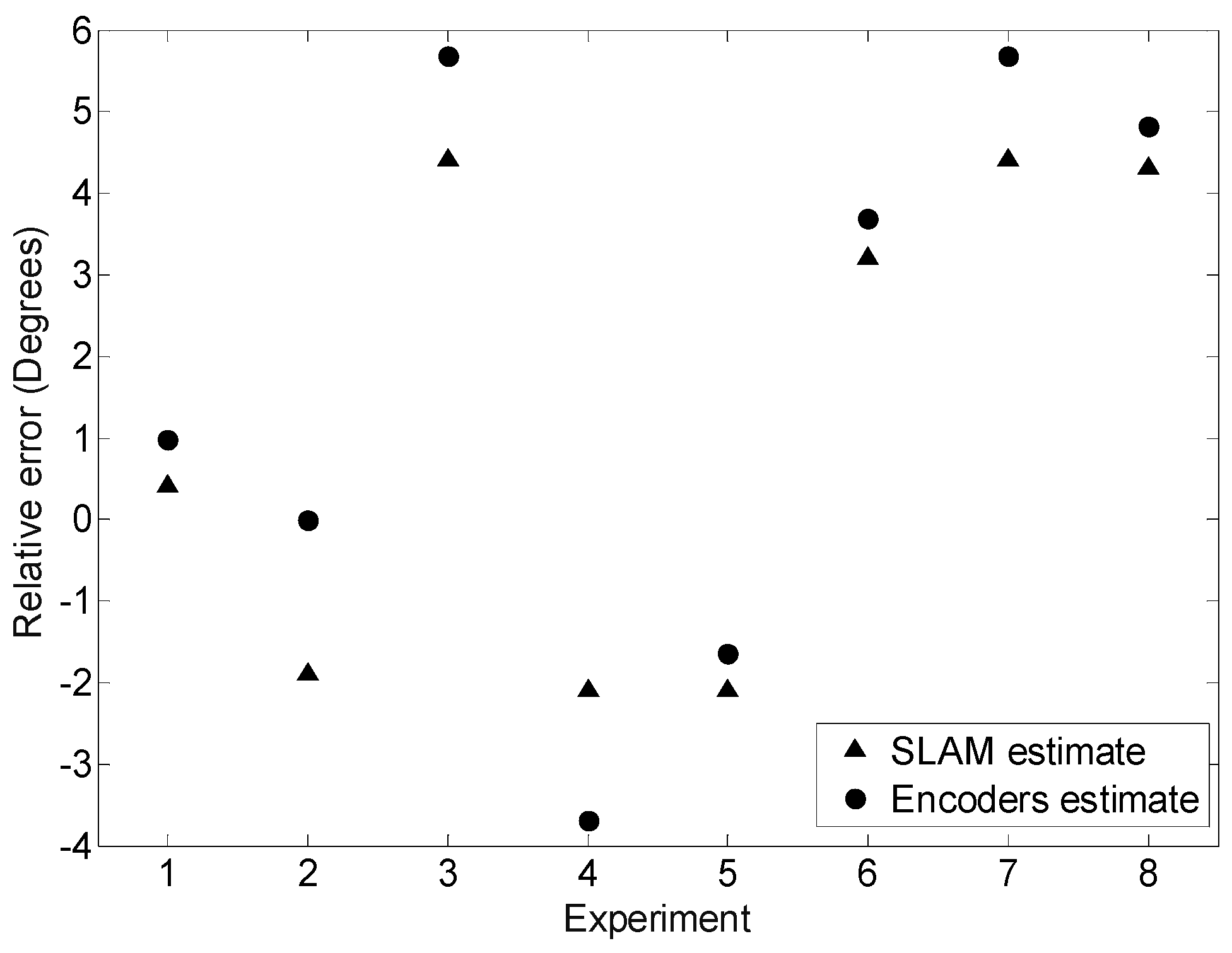
5. Validation
6. Conclusions
Acknowledgments
Author Contributions
Conflicts of Interest
References
- Fish, S. UGVs in future combat systems. In Proceedings of the SPIE 5422 Unmanned Ground Vehicle Technology VI, Orlando, FL, USA, 13–15 April 2004; pp. 288–291.
- Byambasuren, B.E.; Kim, D.; Oyun-Erdene, M.; Bold, C.; Yura, J. Inspection Robot Based Mobile Sensing and Power Line Tracking for Smart Grid. Sensors 2016, 16, 250. [Google Scholar] [CrossRef] [PubMed]
- Bengochea-Guevara, J.M.; Conesa-Muñoz, J.; Andújar, D.; Ribeiro, A. Merge Fuzzy Visual Servoing and GPS-Based Planning to Obtain a Proper Navigation Behavior for a Small Crop-Inspection Robot. Sensors 2016, 16, 276. [Google Scholar] [CrossRef] [PubMed]
- Blitch, J.G. Artificial intelligence technologies for robot assisted urban search and rescue. Expert Syst. Appl. 1996, 11, 109–124. [Google Scholar] [CrossRef]
- Lafaye, J.; Gouaillier, D.; Wieber, P.B. Linear model predictive control of the locomotion of Pepper, a humanoid robot with omnidirectional wheels. In Proceedings of the IEEE-RAS International Conference on Humanoid Robots, Madrid, Spain, 18–20 November 2014; pp. 336–341.
- Wada, M.; Asada, H.H. Design and control of a variable footprint mechanism for holonomic omnidirectional vehicles and its application to wheelchairs. IEEE Trans. Robot. Autom. 1999, 15, 978–989. [Google Scholar] [CrossRef]
- United Nations. World Population Ageing 2013. Available online: http://www.un.org/en/development/desa/population/publications/pdf/ageing/WorldPopulationAgeing2013.pdf (accessed on 15 December 2015).
- World Health Organization. World Report on Ageing and Health, 2015. Available online: http://apps.who.int/iris/bitstream/10665/186463/1/9789240694811_eng.pdf (accessed on 18 February 2016).
- Clotet, E.; Martínez, D.; Moreno, J.; Tresanchez, M.; Palacín, J. Assistant Personal Robot (APR): Conception and Application of a Tele-Operated Assisted Living Robot. Sensors 2016, 16, 610. [Google Scholar] [CrossRef] [PubMed]
- Morón, C.; Payán, A.; García, A.; Bosquet, F. Domotics Project Housing Block. Sensors 2016, 16, 741. [Google Scholar] [CrossRef] [PubMed]
- Mariappan, M.; Sing, J.C.; Wee, C.C.; Khoo, B.; Wong, W.K. Simultaneous rotation and translation movement for four omnidirectional wheels holonomic mobile robot. In Proceedings of the IEEE International Symposium of Robotics and Manufacturing Automation, Kuala Lumpur, Malaysia, 15–16 December 2014; pp. 69–73.
- Muir, P.F.; Neuman, C.P. Kinematic Modeling of Wheeled Mobile Robots; Technical Report, CMU-RETR-8612; Carnegie Mellon University: Pittsburgh, PA, USA, 1986. [Google Scholar]
- Alakshendra, V.; Chiddarwar, S.S.; Jha, A. Trajectory Tracking Control of Three-Wheeled Omnidirectional Mobile Robot: Adaptive Sliding Mode Approach. In CAD/CAM, Robotics and Factories of the Future; Springer: New Delhi, India, 2016; pp. 275–286. [Google Scholar]
- Byun, K.S.; Song, J.B. Design and construction of continuous alternate wheels for an omnidirectional mobile robot. J. Robot. Syst. 2003, 20, 569–579. [Google Scholar] [CrossRef]
- Wada, M.; Mori, S. Holonomic and Omnidirectional Vehicle with Conventional Tires. In Proceedings of the IEEE International Conference on Robotics and Automation, Minneapolis, MN, USA, 22–28 April 1996; pp. 3671–3676.
- Song, J.B.; Byun, K.S. Steering control algorithm for efficient drive of a mobile robot with steerable omni-directional wheels. J. Mech. Sci. Technol. 2009, 23, 2747–2756. [Google Scholar] [CrossRef]
- West, M.; Asada, H. Design of Ball Wheel Mechanisms for Omnidirectional Vehicles with Full Mobility and Invariant Kinematics. J. Mech. Des. 1997, 119, 153–161. [Google Scholar] [CrossRef]
- Endo, T.; Nakamura, Y. An omnidirectional vehicle on a basketball. In Proceedings of the 12th International Conference on Advanced Robotics, Seattle, WA, USA, 18–20 July 2005; pp. 573–578.
- Lauwers, T.B.; Kantor, G.A.; Hollis, R.L. A dynamically stable single-wheeled mobile robot with inverse mouse-ball drive. In Proceedings of the 2006 IEEE International Conference on Robotics and Automation, Orlando, FL, USA, 15–19 May 2006; pp. 2884–2889.
- Kumagai, M.; Ochiai, T. Development of a robot balancing on a ball. In Proceedings of the International Conference on Control, Automation and Systems, Seoul, Korea, 14–17 October 2008; pp. 433–438.
- Endo, G.; Hirose, S. Study on roller-walker (system integration and basic experiments). In Proceedings of the 1999 IEEE International Conference on Robotics and Automation, Detroit, MI, USA, 10–15 May 1999.
- Muir, P.F.; Neuman, C.P. Kinematic Modeling for Feedback Control of an Omnidirectional Wheeled Mobile Robot. Auton. Robot Veh. 1987, 1, 25–31. [Google Scholar]
- Ferriere, L.; Raucent, B.; Campion, G. Design of omnimobile robot wheels. In Proceedings of the IEEE International Conference on Robotics and Automation, Minneapolis, MN, USA, 22–28 April 1996; pp. 3664–3670.
- Blumrich, J. Omnidirectional Wheel. U.S. Patent 3,789,947, 5 February 1974. [Google Scholar]
- Ilon, B.E. Wheels for a Course Stable Selfpropelling Vehicle Movable in Any Desired Direction on the Ground or Some Other Base. U.S. Patent 3,876,255, 8 April 1975. [Google Scholar]
- Martinez, D.; Teixidó, M.; Font, D.; Moreno, J.; Tresanchez, M.; Marco, S.; Palacín, J. Ambient Intelligence Application Based on Environmental Measurements Performed with an Assistant Mobile Robot. Sensors 2014, 14, 6045–6055. [Google Scholar] [CrossRef] [PubMed]
- Teixidó, M.; Pallejà, T.; Font, D.; Tresanchez, M.; Moreno, J.; Palacín, J. Two-dimensional radial laser scanning for circular marker detection and external mobile robot tracking. Sensors 2012, 12, 16482–16497. [Google Scholar] [CrossRef] [PubMed]


| Motion System Based on | ||||
|---|---|---|---|---|
| Wheels | Ball | Legs | ||
| Universal | Omnidirectional | |||
 |  |  | 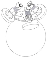 | 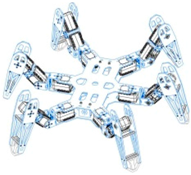 |
 | ||||
| (a) | (b) | (c) | (d) | (e) |
| Not omnidirectional | Omnidirectional | |||
| Type of mobility | ||||
© 2016 by the authors; licensee MDPI, Basel, Switzerland. This article is an open access article distributed under the terms and conditions of the Creative Commons Attribution (CC-BY) license (http://creativecommons.org/licenses/by/4.0/).
Share and Cite
Moreno, J.; Clotet, E.; Lupiañez, R.; Tresanchez, M.; Martínez, D.; Pallejà, T.; Casanovas, J.; Palacín, J. Design, Implementation and Validation of the Three-Wheel Holonomic Motion System of the Assistant Personal Robot (APR). Sensors 2016, 16, 1658. https://doi.org/10.3390/s16101658
Moreno J, Clotet E, Lupiañez R, Tresanchez M, Martínez D, Pallejà T, Casanovas J, Palacín J. Design, Implementation and Validation of the Three-Wheel Holonomic Motion System of the Assistant Personal Robot (APR). Sensors. 2016; 16(10):1658. https://doi.org/10.3390/s16101658
Chicago/Turabian StyleMoreno, Javier, Eduard Clotet, Ruben Lupiañez, Marcel Tresanchez, Dani Martínez, Tomàs Pallejà, Jordi Casanovas, and Jordi Palacín. 2016. "Design, Implementation and Validation of the Three-Wheel Holonomic Motion System of the Assistant Personal Robot (APR)" Sensors 16, no. 10: 1658. https://doi.org/10.3390/s16101658
APA StyleMoreno, J., Clotet, E., Lupiañez, R., Tresanchez, M., Martínez, D., Pallejà, T., Casanovas, J., & Palacín, J. (2016). Design, Implementation and Validation of the Three-Wheel Holonomic Motion System of the Assistant Personal Robot (APR). Sensors, 16(10), 1658. https://doi.org/10.3390/s16101658