
Six-Port Based Interferometry for Precise Radar and Sensing Applications


Abstract
:1. Introduction
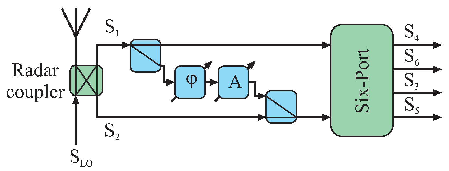
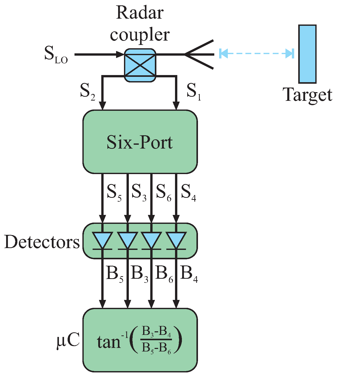
2. Six-Port Architecture
2.1. Basic Principle
2.2. Building Blocks
2.2.1. Basic Building Blocks
Six-Port Structure
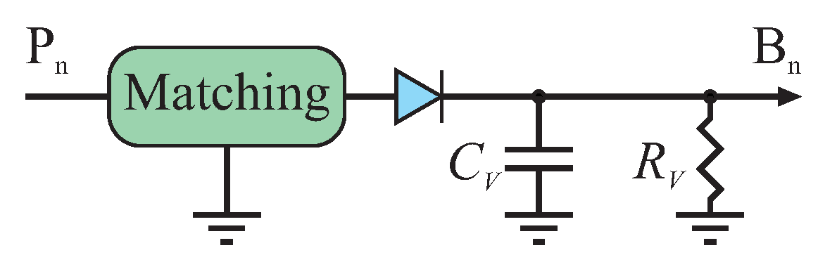
Power Detector
Baseband Processing
2.2.2. Advanced Building Blocks
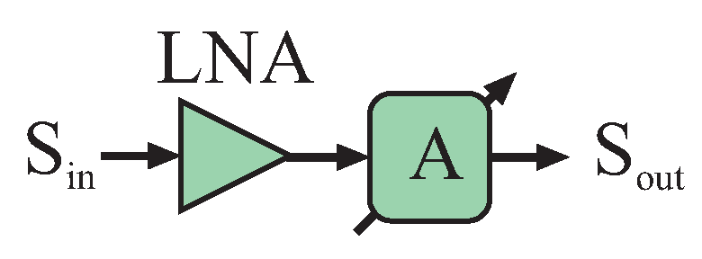
Low Noise Amplifier
Variable Attenuator
Automatic Gain Control
Offset Compensation Circuitry
Microwave Switch
3. Six-Port in Metrology
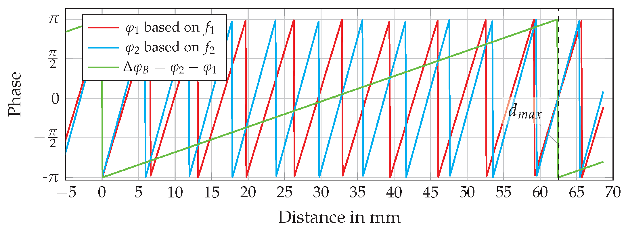
3.1. Distance
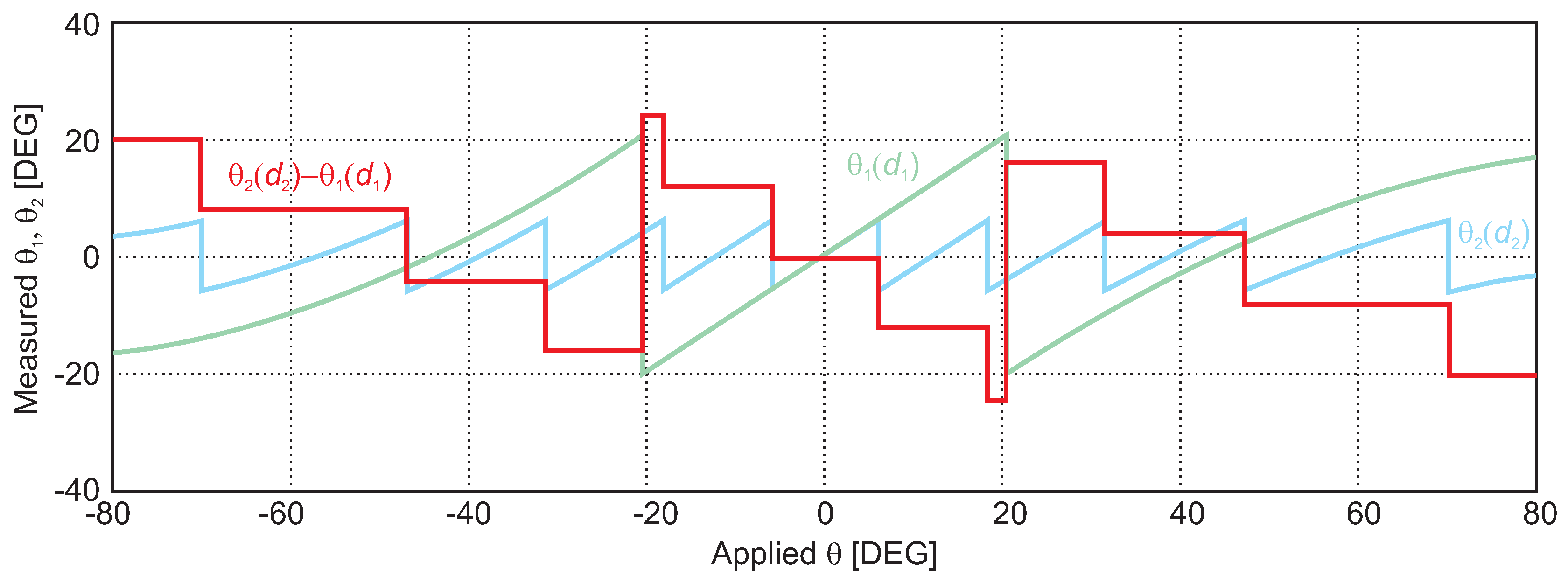
3.2. Angle of Arrival
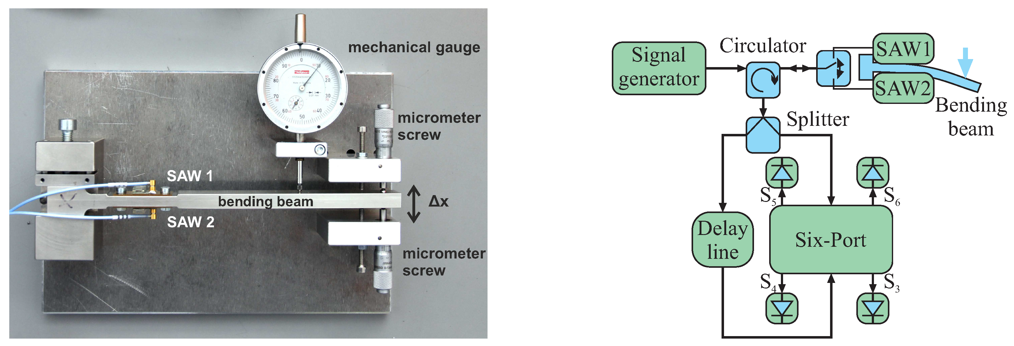
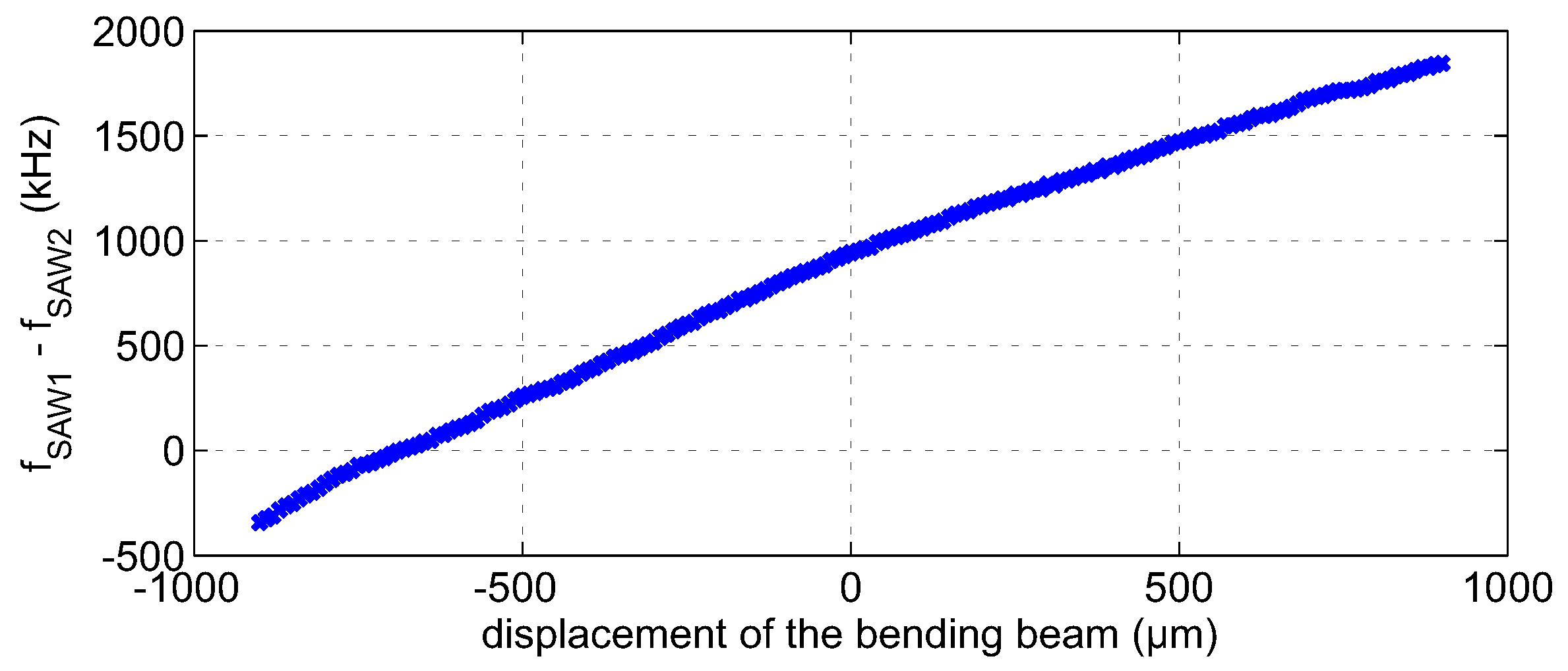
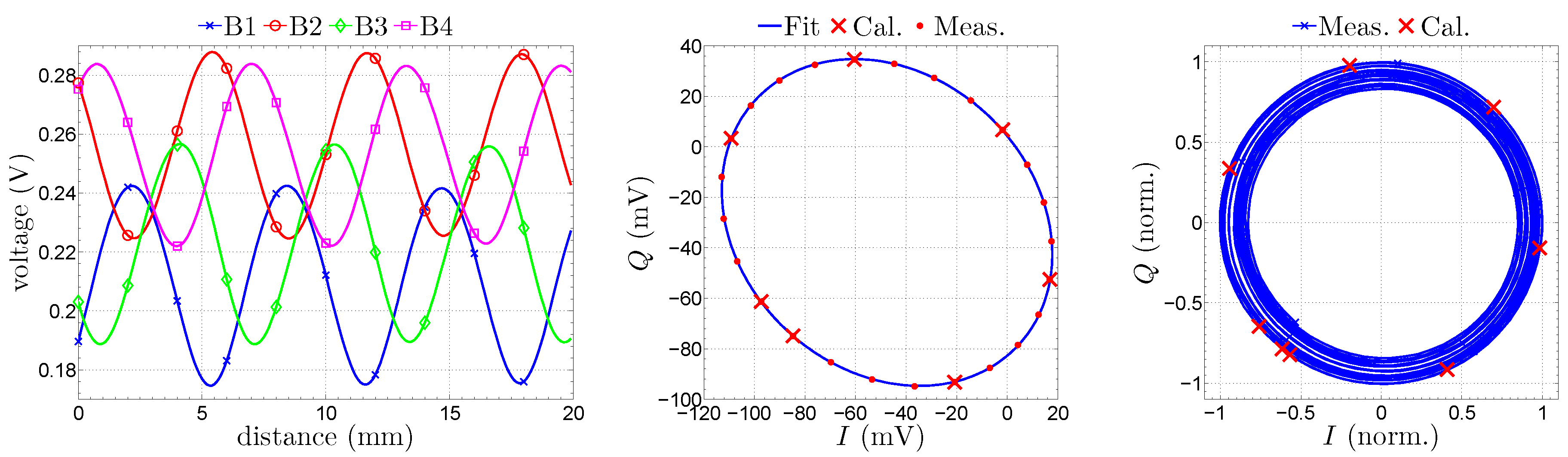
3.3. Mechanical Strain
4. Non-Ideal Behavior of the Six-Port
4.1. Static Offset
4.2. Dynamic Offset
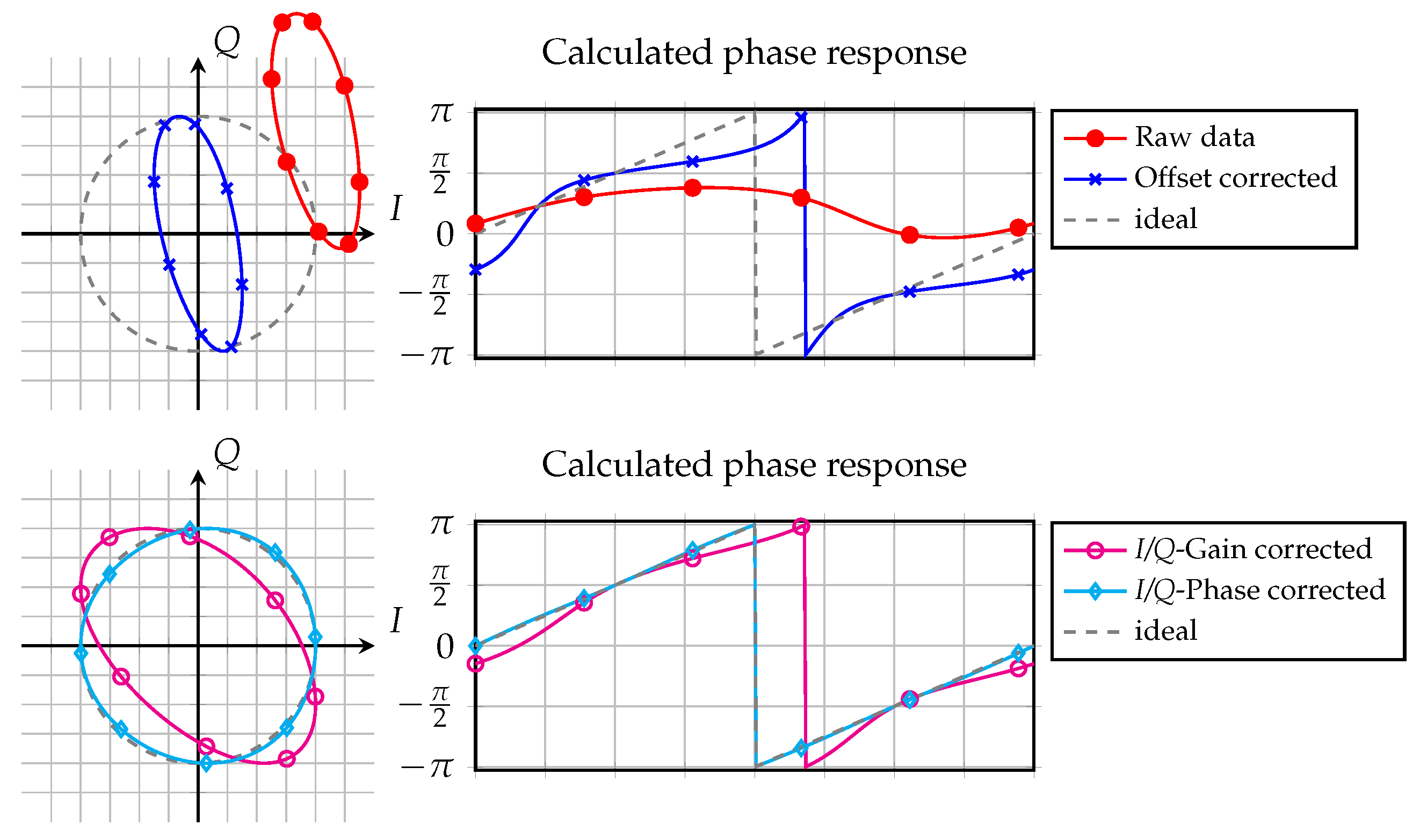
4.3. I/Q Impairments
4.4. Linearization and Compensation Techniques
4.4.1. I/Q Equalization
4.4.2. Offset Compensation
4.4.3. Detector Linearization
5. Discussion
5.1. The Six-Port Concept’s Benefits and Drawbacks
5.1.1. Ambiguities
5.1.2. Multi-Path and Multi-Target Effects
5.1.3. Current Challenges in Six-Port Research
5.2. Comparison to State-Of-The-Art Industrial Remote Metrology
6. Conclusions
Acknowledgments
Author Contributions
Conflicts of Interest
References
- Jaeschke, T.; Bredendiek, C.; Kuppers, S.; Pohl, N. High-Precision D-Band FMCW-Radar Sensor Based on a Wideband SiGe-Transceiver MMIC. IEEE Trans. Microw. Theory Tech. 2014, 62, 3582–3597. [Google Scholar] [CrossRef]
- Engen, G.F. An Introduction to the Description and Evaluation of Microwave Systems Using Terminal Invariant Parameters; National Bureau of Standards: Washington, DC, USA, 1969. [Google Scholar]
- Engen, G. The six-port Reflectometer: An Alternative Network Analyzer. IEEE Trans. Microw. Theory Tech. 1977, 25, 1075–1080. [Google Scholar] [CrossRef]
- Engen, G. A (Historical) Review of the six-port Measurement Technique. IEEE Trans. Microw. Theory Tech. 1997, 45, 2414–2417. [Google Scholar] [CrossRef]
- Ghannouchi, F.M.; Mohammadi, A. The Six-Port Technique; Artech House: Norwood, MA, USA, 2009. [Google Scholar]
- Caron, M.; Akyel, A.; Ghannouchi, F.M. A Versatile Easy to Do six-port Based High Power Reflectometer. J. Microw. Power Electromagn. Energy 1995, 30, 231–239. [Google Scholar] [CrossRef]
- De Souza Rolim, A.L.; Belfort de Oliveira, A.J.; de Melo, M.T. Six-port Complex Permittivity Measurements. In Proceedings of the European Microwave Conference, EuMC 2006, Kyoto, Japan, 10–15 September 2006; pp. 492–494.
- Wang, M.; Haddadi, K.; Glay, D.; Lasri, T. Compact near-field microwave microscope based on the multi-port technique. In Proceedings of the European Microwave Conference, EuMC 2010, Paris, France, 26 September–1 October 2010; pp. 771–774.
- Hentschel, T. The six-port as a Communications Receiver. IEEE Trans. Microw. Theory Tech. 2005, 53, 1039–1047. [Google Scholar] [CrossRef]
- Bosisio, R.G.; Zhao, Y.Y.; Xu, X.Y.; Abielmona, S.; Moldovan, E.; Xu, Y.S.; Bozzi, M.; Tatu, S.O.; Nerguizian, C.; Frigon, J.F.; et al. New-Wave Radio. IEEE Microw. Mag. 2008, 9, 89–100. [Google Scholar] [CrossRef]
- Hannachi, C.; Tatu, S.O. A new compact V-band six-port receiver for high data-rate wireless applications. In Proceedings of the 2015 IEEE Topical Conference on Wireless Sensors and Sensor Networks (WiSNet), San Diego, CA, USA, 25–28 January 2015; pp. 26–28.
- Tatu, S.; Serban, A.; Helaoui, M.; Koelpin, A. Multiport Technology: The New Rise of an Old Concept. IEEE Microw. Mag. 2014, 15, 34–44. [Google Scholar] [CrossRef]
- Li, J.; Bosisio, R.; Wu, K. A Collision Avoidance Radar Using six-port Phase/Frequency Discriminator (SPFD). In Proceedings of the IEEE MTT-S International Microwave Symposium Digest, San Diego, CA, USA, 23–27 May 1994; Volume 3, pp. 1553–1556.
- Stelzer, A.; Diskus, C.; Lubke, K.; Thim, H. A Microwave Position Sensor with Submillimeter Accuracy. IEEE Trans. Microw. Theory Tech. 1999, 47, 2621–2624. [Google Scholar] [CrossRef]
- Gutierrez Miguelez, C.; Huyart, B.; Bergeault, E.; Jallet, L.P. A New Automobile Radar Based on the six-port Phase/Frequency Discriminator. IEEE Trans. Veh. Technol. 2000, 49, 1416–1423. [Google Scholar] [CrossRef]
- Moldovan, E.; Tatu, S.O.; Gaman, T.; Wu, K.; Bosisio, R.G. A New 94-GHz six-port Collision-Avoidance Radar Sensor. IEEE Trans. Microw. Theory Tech. 2004, 52, 751–759. [Google Scholar] [CrossRef]
- Boukari, B.; Moldovan, E.; Affes, S.; Wu, K.; Bosisio, R.; Tatu, S.O. Six-port FMCW collision avoidance radar sensor configurations. In Proceedings of the Canadian Conference on Electrical and Computer Engineering, CCECE 2008, Niagara Falls, ON, Canada, 4–7 May 2008; pp. 305–308.
- Haddadi, K.; Lasri, T. V-band two-tone continuous wave radar operating in monostatic/bistatic mode. In Proceedings of the 2012 9th European Radar Conference (EuRAD), Amsterdam, The Netherlands, 31 October–2 November 2012; pp. 266–269.
- Haddadi, K.; Lasri, T. The muti-port technology for microwave sensing applications. In Proceedings of the 2012 IEEE MTT-S International Microwave Symposium Digest (MTT), Montreal, QC, Canada, 17–22 June 2012; pp. 1–3.
- Haddadi, K.; Lasri, T. Six-port technology for millimeter-wave radar and imaging applications. In Proceedings of the 2014 IEEE Topical Conference on Wireless Sensors and Sensor Networks (WiSNet), Newport Beach, CA, USA, 19–23 January 2014; pp. 1–3.
- Koelpin, A.; Vinci, G.; Laemmle, B.; Kissinger, D.; Weigel, R. The six-port in Modern Society. Microw. Mag. 2010, 11, 35–43. [Google Scholar] [CrossRef]
- Xu, Y.; Bosisio, R.G. Effects of local oscillator leakage in digital millimetric six-port receivers (SPRs). Microw. Opt. Technol. Lett. 1998, 19, 27–34. [Google Scholar] [CrossRef]
- Li, J.; Bosisio, R.; Wu, K. A six-port Direct Digital Millimeter Wave Receiver. In Proceedings of the IEEE MTT-S International Microwave Symposium Digest, San Diego, CA, USA, 26–28 May 1994; Volume 3, pp. 1659–1662.
- Schiel, J.C.; Tatu, S.O.; Wu, K.; Bosisio, R.G. Six-port Direct Digital Receiver (SPDR) and Standard Direct Receiver (SDR) Results for QPSK Modulation at High Speeds. In Proceedings of the 2002 IEEE MTT-S International Microwave Symposium Digest, Baltimore, MD, USA, 2–7 June 2002; Volume 2, pp. 931–934.
- Luy, J.F.; Mueller, T.; Mack, T.; Terzis, A. Configurable RF receiver architectures. IEEE Microw. Mag. 2004, 5, 75–82. [Google Scholar] [CrossRef]
- Seman, N.; Bialkowski, M.; Ibrahim, S.; Bakar, A. Design of an Integrated Correlator for Application in Ultra Wideband six-port Transceivers. In Proceedings of the IEEE Antennas and Propagation Society International Symposium, APSURSI ’09, Charleston, SC, USA, 1–5 June 2009; pp. 1–4.
- Haddadi, K.; Wang, M.M.; Loyez, C.; Glay, D.; Lasri, T. Four-Port Communication Receiver With Digital IQ-Regeneration. IEEE Microw. Wirel. Compon. Lett. 2010, 20, 58–60. [Google Scholar] [CrossRef]
- Koelpin, A. Der Erweiterte Sechstor-Empfänger Ein Systemübergreifender Ansatz für Kommunikations-und Messaufgaben. Ph.D. Thesis, Friedrich-Alexander University of Erlangen-Nuremberg, Erlangen, Germany, 2010. [Google Scholar]
- Xu, X.; Bosisio, R.G.; Wu, K. Analysis and implementation of six-port software-defined radio receiver platform. IEEE Trans. Microw. Theory Tech. 2006, 54, 2937–2943. [Google Scholar]
- Akyel, C.; Ghannouchi, F.M.; Caron, M. A New Design for High-Power six-port Reflectometers using Hybrid Stripline/Waveguide Technology. IEEE Trans. Instrum. Meas. 1994, 43, 316–321. [Google Scholar] [CrossRef]
- Boulejfen, N.; Kouki, A.; Khouaja, S.; Ghannouchi, F.M. A homodyne multi-port network analyzer for S parameter measurements of microwave N-port circuits/systems. In Proceedings of the 1998 IEEE Asia-Pacific Conference on Circuits and Systems, Chiangmai, Thailand, 24–27 November 1998; pp. 687–689.
- Yakabe, T.; Ghannouchi, F.M.; Eid, E.E.; Fujii, K.; Yabe, H. Six-port self-calibration based on active loads synthesis. IEEE Trans. Microw. Theory Tech. 2002, 50, 1237–1239. [Google Scholar] [CrossRef]
- Tatu, S.O.; Cojocaru, R.I.; Moldovan, E. Interferometric quadrature down-converter for 77 GHz automotive radar: Modeling and analysis. In Proceedings of the 2010 European Radar Conference (EuRAD), Paris, France, 30 September–1 October 2010; pp. 125–128.
- Zhang, H.; Li, L.; Wu, K. Software-Defined six-port Radar Technique for Precision Range Measurements. IEEE Sens. J. 2008, 8, 1745–1751. [Google Scholar] [CrossRef]
- Xiao, F.; Ghannouchi, F.; Yakabe, T. Application of a six-port wave-correlator for a very low velocity measurement using the Doppler effect. IEEE Trans. Instrum. Meas. 2003, 52, 297–301. [Google Scholar] [CrossRef]
- Djerafi, T.; Daigle, M.; Boutayeb, H.; Zhang, X.; Wu, K. Substrate Integrated Waveguide six-port Broadband Front-End Circuit for Millimeter-Wave Radio and Radar Systems. In Proceedings of the European Microwave Conference, EuMC 2009, Rome, Italy, 29 September–1 October 2009; pp. 77–80.
- Vinci, G.; Lindner, S.; Barbon, F.; Weigel, R.; Koelpin, A. Promise of a Better Position. Microw. Mag. 2012, 13, 41–49. [Google Scholar] [CrossRef]
- Mann, S.; Erhardt, S.; Lindner, S.; Lurz, F.; Linz, S.; Barbon, F.; Weigel, R.; Koelpin, A. Diode Detector Design for 61 GHz Substrate Integrated Waveguide six-port Radar Systems. In Proceedings of the IEEE Topical Conference on Wireless Sensors and Sensor Networks (WiSNet), San Diego, CA, USA, 25–28 January 2015; pp. 44–46.
- Xu, X.; Bosisio, R.G.; Wu, K. A new six-port junction based on substrate integrated waveguide technology. IEEE Trans. Microw. Theory Tech. 2005, 53, 2267–2273. [Google Scholar]
- Mann, S.; Lurz, F.; Linz, S.; Lindner, S.; Will, C.; Wibbing, S.; Weigel, R.; Koelpin, A. Substrate Integrated Waveguide Fed Antenna for 61 GHz Ultra-Short-Range Interferometric Radar Systems. In Proceedings of the IEEE Topical Conference on Wireless Sensors and Sensor Networks (WiSNet), Austin, TX, USA, 24–27 January 2016; Volume 64, pp. 64–66.
- Garcia, B.A.; Kerneves, D.; Huyart, B. Measurement of Direction of Arrival for Radar Application. In Proceedings of the 32nd European Microwave Conference, Milan, Italy, 6–26 September 2002; pp. 1–4.
- Vinci, G.; Barbon, F.; Weigel, R.; Koelpin, A. A Novel, Wide Angle, High Resolution Direction-Of-Arrival Detector. In Proceedings of the European Microwave Week (EuMW), Manchester, UK, 9–14 October 2011; pp. 265–268.
- Koelpin, A.; Vinci, G.; Laemmle, B.; Lindner, S.; Barbon, F.; Weigel, R. Six-port Technology for Traffic Safety. IEEE Microw. Mag. 2012, 13, 118–127. [Google Scholar] [CrossRef]
- Buff, W.; Klett, S.; Rusko, M.; Ehrenpfordt, J.; Goroli, M. Passive remote sensing for temperature and pressure using SAW resonator devices. IEEE Trans. Ultrason. Ferroelectr. Freq. Control 1998, 45, 1388–1392. [Google Scholar] [CrossRef]
- Pohl, A.; Ostermayer, G.; Seifert, F. Wireless sensing using oscillator circuits locked to remote high-Q SAW resonators. IEEE Trans. Ultrason. Ferroelectr. Freq. Control 1998, 45, 1161–1168. [Google Scholar] [CrossRef] [PubMed]
- Beckley, J.; Kalinin, V.; Lee, M.; Voliansky, K. Non-contact torque sensors based on SAW resonators. In Proceedings of the IEEE International Frequency Control Symposium and PDA Exhibition, New Orleans, LA, USA, 29–31 May 2002; pp. 202–213.
- Hamsch, M.; Hoffmann, R.; Buff, W.; Binhack, M.; Klett, S. An interrogation unit for passive wireless SAW sensors based on Fourier transform. IEEE Trans. Ultrason. Ferroelectr. Freq. Control 2004, 51, 1449–1456. [Google Scholar] [CrossRef] [PubMed]
- Kalinin, V.; Beckley, J.; Makeev, I. High-speed reader for wireless resonant SAW sensors. In Proceedings of the European Frequency and Time Forum (EFTF), Gothenburg, Sweden, 23–27 April 2012; pp. 428–435.
- Lurz, F.; Lindner, S.; Mann, S.; Linz, S.; Weigel, R.; Koelpin, A. Precise and Fast Frequency Determination of Resonant SAW Sensors by a Low-Cost six-port Interferometer. In Proceedings of the IEEE International Instrumentation and Measurement Technology Conference (I2MTC), Taipei, Taiwan, 23–26 May 2016; pp. 369–374.
- East, P. Fifty years of instantaneous frequency measurement. Radar Sonar Navig. IET 2012, 6, 112–122. [Google Scholar] [CrossRef]
- Buff, W.; Rusko, M.; Vandahl, T.; Goroll, M.; Moller, F. A differential measurement SAW device for passive remote sensoring. In Proceedings of the Ultrasonics Symposium, San Antonio, TX, USA, 3–6 November 1996; Volume 1, pp. 343–346.
- Lurz, F.; Lindner, S.; Mann, S.; Linz, S.; Barbon, F.; Weigel, R.; Koelpin, A. A Low-Cost 2.4 GHz Frequency Measurement System for Microsecond Time Domain Pulses Based on six-port Technology. In Proceedings of the 44th European Microwave Week, EuMA, Rome, Italy, 6–9 October 2014; pp. 171–174.
- Mailand, M.; Richter, R. Blind IQ-Regeneration for six-port-Based Direct Conversion Receiver with Low Analog Complexity. In Proceedings of the 11th European Wireless Conference 2005–Next Generation Wireless and Mobile Communications and Services (European Wireless), Athens, Greece, 10–13 April 2005; pp. 1–7.
- Park, B.K.; Boric-Lubecke, O.; Lubecke, V.M. Arctangent Demodulation With DC Offset Compensation in Quadrature Doppler Radar Receiver Systems. IEEE Trans. Microw. Theory Tech. 2007, 55, 1073–1079. [Google Scholar] [CrossRef]
- Mann, S.; Vinci, G.; Lindner, S.; Linz, S.; Barbon, F.; Weigel, R.; Koelpin, A. 61 GHz six-port Radar Frontend for High Accuracy Range Detection Applications. In Proceedings of the IEEE-APS Topical Conference on Antennas and Propagation in Wireless Communications, Torino, Italy, 9–13 September 2013.
- Linz, S.; Vinci, G.; Lindner, S.; Mann, S.; Lurz, F.; Barbon, F.; Weigel, R.; Koelpin, A. I/Q Imbalance Compensation for six-port Interferometers in Radar Applications. In Proceedings of the 2014 IEEE European Microwave Conference (EuMC), Rome, Italy, 6–9 October 2014; pp. 746–749.
- Singh, A.; Gao, X.; Yavari, E.; Zakrzewski, M.; Cao, X.H.; Lubecke, V.; Boric-Lubecke, O. Data-based quadrature imbalance compensation for a CW Doppler radar system. IEEE Trans. Microw. Theory Tech. 2013, 61, 1718–1724. [Google Scholar] [CrossRef]
- Sporer, M.; Lurz, F.; Schluecker, E.; Weigel, R.; Koelpin, A. Underwater Interferometric Radar Sensor for Distance and Vibration Measurement. In Proceedings of the IEEE Topical Conference on Wireless Sensors and Sensor Networks (WiSNet), Michael Sporer, San Diego, CA, USA, 25–28 January 2015; pp. 72–74.
- Hoer, C.A.; Roe, K.C.; Allred, C.M. Measuring and minimizing diode detector nonlinearity. IEEE Trans. Instrum. Meas. 1976, IM-25, 324–329. [Google Scholar] [CrossRef]
- Colef, G.; Karmel, P.R.; Ettenberg, M. New in-situ calibration of diode detectors used in six-port network analyzers. IEEE Trans. Instrum. Meas. 1990, 39, 201–204. [Google Scholar] [CrossRef]
- Juroshek, J.R.; Hoer, C.A. A Dual six-port Network Analyzer Using Diode Detectors. IEEE Trans. Microw. Theory Tech. 1984, 32, 78–82. [Google Scholar] [CrossRef]
- Barbon, F.; Lindner, S.; Mann, S.; Linz, S.; Weigel, R.; Koelpin, A. Fast In-Situ Diode Detector Characterization for six-port Interferometer Receivers. In Proceedings of the 2014 IEEE Radio and Wireless Week (RWW 2014), Newport Beach, CA, USA, 19–22 January 2014.
- Koelpin, A.; Linz, S.; Barbon, F.; Lindner, S.; Mann, S.; Lurz, F.; Weigel, R. Selftest Strategies for Microwave Interferometry for High-Precision Industrial Distance Measurements. In Proceedings of the 20th International Conference on Microwaves, Radar, and Wireless Communications, Gdansk, Poland, 16–18 June 2014.
- Staszek, K.; Linz, S.; Lurz, F.; Mann, S.; Weigel, R.; Koelpin, A. Improved Calibration Procedure for six-port Based Precise Displacement Measurements. In Proceedings of the IEEE Topical Conference on Wireless Sensors and Sensor Networks (WiSNet), Austin, TX, USA, 24–27 January 2016; pp. 60–63.
- Lindner, S.; Barbon, F.; Linz, S.; Lurz, F.; Mann, S.; Weigel, R.; Koelpin, A. ADC Depending Limitations for six-port Based Distance Measurement Systems. In Proceedings of the IEEE Topical Conference on Wireless Sensors and Sensor Networks 2015 (WiSNet), San Diego, CA, USA, 25–28 January 2015; pp. 29–31.
- Barbon, F.; Vinci, G.; Lindner, S.; Weigel, R.; Koelpin, A. Signal Processing Strategies for six-port Based Direction of Arrival Detector Systems. In Proceedings of the 2012 9th International Multi-Conference on Systems, Signals and Devices (SSD), Chemnitz, Germany, 20–23 March 2012.
- Lindner, S.; Barbon, F.; Mann, S.; Vinci, G.; Weigel, R.; Koelpin, A. Dual tone approach for unambiguous six-port based interferometric distance measurements. In Proceedings of the IEEE MTT-S International Microwave Symposium, Seattle, WA, USA, 2–7 June 2013; pp. 1–4.
- Lindner, S.; Barbon, F.; Linz, S.; Mann, S.; Weigel, R.; Koelpin, A. Distance measurements and limitations based on guided wave 24GHz dual tone six-port radar. Int. J. Microw. Wirel. Technol. 2015, 7, 425–432. [Google Scholar] [CrossRef]
- Olopade, A.O.; Helaoui, M. Mitigation of distortion and memory effect in a concurrent dual-band six port receiver. In Proceedings of the 2014 44th European Microwave Conference (EuMC), Rome, Italy, 6–9 October 2014; pp. 1138–1141.
- Judah, S.R.; Holmes, W. A novel sixport calibration incorporating diode detector non-linearity. In Proceedings of the IEEE Conference Proceedings Instrumentation and Measurement Technology Conference, St. Paul, MN, USA, 18–21 May 1998; Volume 1, pp. 592–595.
- Moldovan, E.; Tatu, S.O. Design and characterization of novel W-band wide-band couplers and six-port circuit. In Proceedings of the 2015 European Microwave Conference (EuMC), Paris, France, 6–11 September 2015; pp. 279–282.
- Haddadi, K.; Loyez, C. 65 nm SOI CMOS 60 GHz passive mixer for six-port technology. In Proceedings of the 2016 IEEE Topical Conference on Wireless Sensors and Sensor Networks (WiSNet), Austin, TX, USA, 24–27 January 2016; pp. 52–55.
- Chioukh, L.; Djerafi, T.; Deslandes, D.; Wu, K. Improvements of cardiopulmonary monitoring using harmonic six-port radar system. In Proceedings of the 2015 Global Symposium On Millimeter Waves (GSMM), Montreal, QC, Canada, 25–27 May 2015; pp. 1–3.
- Haddadi, K.; Lasri, T. Forward V-band vector network analyzer based on a modified six-port technique. In Proceedings of the 2015 IEEE Topical Conference on Wireless Sensors and Sensor Networks (WiSNet), San Diego, CA, USA, 25–28 January 2015; pp. 23–25.
- Hasan, A.; Helaoui, M.; Boulejfen, N.; Ghannouchi, F.M. Six-port technology for MIMO and cognitive radio receiver applications. In Proceedings of the 2015 IEEE Topical Conference on Wireless Sensors and Sensor Networks (WiSNet), San Diego, CA, USA, 25–28 January 2015; pp. 17–19.
- Oesth, J.; Karlsson, M.; Serban, A.; Gong, S. A Comparative Study of Single-Ended vs. Differential six-port Modulators for Wireless Communications. IEEE Trans. Circ. Syst. I Regul. Pap. 2015, 62, 564–570. [Google Scholar] [CrossRef]
- Hering, E.; Schoenfelder, G. (Eds.) Sensoren in Wissenschaft und Technik; Vieweg + Teubner Verlag: Wiesbaden, Germany, 2012; p. 323. (In German)
- Photoelectric Distance Sensor. BOD26K-LA02-C-06. Balluff: Neuhausen, Germany, 15 September 2016.
- Distance Sensor. VDM35-6-L/20/105/122. Pepperl+Fuchs: Mannheim, Germany, 15 September 2016.
- Statuspro μLine F1 Laser Interferometer. TD1058 D 05/2012. Statuspro: Bochum, Germany, 18 January 2014.
- Ultrasonic Sensor. BUS004E. Balluff: Neuhausen, Germany, 15 September 2016.
- NOVOSTRICTIVE Transducer up to 4250 mm touchless series TP1. Novotechnik: Ostfildern, Germany, 15 September 2016.
- SITRANS LR260 (PROFIBUS PA). Siemens: Munich, Germany, 15 September 2016.
- 24 GHz Non-contact Radar (FMCW) Level Meter Optiwave 7300C. KROHNE 06/2011-4000418405-TD OPTIWAVE 7300 R11 de. Krohne Messtechnik GmbH: Duisburg, Germany, 15 September 2016.
- Linz, S.; Vinci, G.; Lindner, S.; Mann, S.; Barbon, F.; Weigel, R.; Koelpin, A. A Compact, Versatile six-port Radar Sensor for Industrial and Medical Applications. IEEE Sens. 2013, 2013, 382913. [Google Scholar]
- InnoSenT. IVS-948; InnoSenT: Donnersdorf, Germany, 2016. [Google Scholar]
- InnoSenT. IPM-165 Low-Cost Radar Transceiver; InnoSenT: Donnersdorf, Germany, 2016. [Google Scholar]
- InnoSenT. iSYS-4001-Systems, 1.1–21.03.2013 ed.; InnoSenT: Donnersdorf, Germany, 2016. [Google Scholar]
- Koelpin, A.; Weigel, R. Six-port Based Direction Finding and Ranging. In Proceedings of the 20th International Conference on Microwaves, Radar, and Wireless Communications, Gdansk, Poland, 16–18 June 2014; pp. 1–5.


| Principle | Typical Measurement Range | Precision | Measurement Value Update Rate |
|---|---|---|---|
| Inductive | 0.1 mm to 50 mm | 100 µm to 50 µm | 1 kHz |
| Capacitive | 0 mm to 10 mm | 100 µm to 50 µm | 100 Hz |
| Optical Triangulation | 45 mm to 85 mm [78] | 20 µm (1) [78] | 40 Hz [78] |
| Optical Time-of-Flight | 200 mm to 6000 mm | mm [79] | 40 Hz [79] |
| Optical Interferometry | 0 mm to 4000 mm | 1 µm [80] | 100 MHz [80] |
| Ultrasonic | 250 mm to 4000 mm | 1 mm to 500 µm | 15 Hz to 250 Hz [81] |
| Magnetostrictive | 25 mm to 2000 mm | 50 µm to 10 µm | 1.5 kHz [82] |
| Principle | Frequency | Typical Measurement Range | Precision | Measurement Value Update Rate | Citation |
|---|---|---|---|---|---|
| Pulse | 25 GHz | 0.21 m to 13 m | 10 mm (1) | 0.5 Hz | [83] |
| FMCW | 24 GHz to 26 GHz | 0.2 m to 80 m | mm | 10 Hz (2) | [84] |
| six-port | 24 GHz | 0.01 m to 2.0 m (3) | µm | 20 Hz (4) | [85] |
© 2016 by the authors; licensee MDPI, Basel, Switzerland. This article is an open access article distributed under the terms and conditions of the Creative Commons Attribution (CC-BY) license (http://creativecommons.org/licenses/by/4.0/).
Share and Cite
Koelpin, A.; Lurz, F.; Linz, S.; Mann, S.; Will, C.; Lindner, S. Six-Port Based Interferometry for Precise Radar and Sensing Applications. Sensors 2016, 16, 1556. https://doi.org/10.3390/s16101556
Koelpin A, Lurz F, Linz S, Mann S, Will C, Lindner S. Six-Port Based Interferometry for Precise Radar and Sensing Applications. Sensors. 2016; 16(10):1556. https://doi.org/10.3390/s16101556
Chicago/Turabian StyleKoelpin, Alexander, Fabian Lurz, Sarah Linz, Sebastian Mann, Christoph Will, and Stefan Lindner. 2016. "Six-Port Based Interferometry for Precise Radar and Sensing Applications" Sensors 16, no. 10: 1556. https://doi.org/10.3390/s16101556
APA StyleKoelpin, A., Lurz, F., Linz, S., Mann, S., Will, C., & Lindner, S. (2016). Six-Port Based Interferometry for Precise Radar and Sensing Applications. Sensors, 16(10), 1556. https://doi.org/10.3390/s16101556