1. Introduction
Foot clearance, defined as the foot elevation during the stride phase, is an important indicator of gait quality and safety in subjects with disabilities [
1]. The minimum foot clearance is one of common gait deviations in people with stroke, which increase the risk of unsuccessful foot clearance (trips) and then of falls [
2,
3]. In a previous study, we showed that this parameter could be used to adapt the applied functional electrical stimulation in the context of drop foot correction in subjects with post-stroke hemiplegia [
4]. In the present study, foot clearance (FC) is defined as the continuous heel height relative to the ground, whereas in other previous studies, maximum or minimum FC values during the stride phase were used instead [
5].
Optical motion capture systems (OMCS) are the most commonly-used devices for measuring foot elevation during walking, providing high accuracy and direct measurement of the position of reflective markers located on body landmarks. However, these devices present multiple drawbacks, such as limited operating space and high cost, making their clinical use technically and financially difficult to implement.
The use of wearable devices, such as inertial measurement units (IMU) presents a promising alternative for gait analysis in outdoor and clinical contexts [
6,
7]. Such devices typically include three-axis accelerometers, three-axis gyroscopes and three-axis magnetometer sensors.
Raw data provided by IMU sensors requires complex post-processing, creating a source of errors in the estimation of IMU displacement and orientation. A major IMU raw data processing issue is the integration of acceleration signals and angular velocity signals (provided by gyroscopes). It is well known that the numerical integration of such data suffers from a high drift error rate, introducing significant errors in the estimation of IMU position and orientation. Magnetometers, on the other hand, provide an absolute orientation and do not require numerical integration. However, such systems can be disturbed by ferromagnetic materials, thus making this technique not reliable everywhere.
In the past few years, several teams have focused on the use and processing of IMU data for human motion analysis. Some authors have estimated IMU orientation based only on gyroscope data [
8,
9], or in combination with acceleration data [
10], or acceleration and magnetometer data [
10,
11], using data fusion algorithms to overcome integration drift problems. To achieve driftless integration using gyroscope data alone, a weighted Fourier linear combiner (WFLC) algorithm [
8] and an empirical mode decomposition (EMD) method [
9] have been proposed for estimating the 3D orientation of the lower trunk during walking. Other authors have developed human biomechanical models to estimate joint angles [
12] or walking parameters, such as stride length [
13], based on IMU orientation estimates.
Only a few authors have focused on the estimation of IMU position or displacement based on acceleration data, mainly because such data require not single, but double integration, which makes the integration drift problem even more significant. In an effort to overcome this issue, an extended Kalman filter has been applied to fuse inertial (accelerometer and gyroscope) sensor data and magnetic sensor data for body position and orientation tracking [
14].
Acceleration-based estimation of foot displacement during walking appears to be very complex due to the high accelerations involved. Therefore, only a few authors have investigated this approach. A simple biomechanical foot model (heel-toe distance) has been used to estimate maximum heel clearance and minimum toe clearance values with a mean error of approximately 4.1 cm and 1.3 cm, respectively [
15]. These results were obtained with 12 healthy participants.
Only a few techniques not involving the use of a biomechanical foot model have been explored to avoid increased drift errors during walking [
5,
16,
17,
18,
19,
20]. Such a method has been applied to estimate maximum foot clearance values from double integration of acceleration data [
16]. These authors used an optimally-filtered direct and reverse integration (OFDRI) technique based on frequency domain analysis of signals to be integrated [
21]. Another published method is based on time domain analysis and the application of the zero velocity update (ZVU) principle. This method relies on the detection of foot-flat periods (
i.e., foot in contact with the ground) to set the velocity to a known constant value [
17] or zero [
18]. Such events can be detected using a foot-switch sensor [
22] or based on the analysis of accelerometer and gyroscope data [
23,
24].
Based on the ZVU principle, integrated acceleration can be corrected using so-called “de-drifted” integration techniques [
5,
17]. Linear de-drifted integration has been applied in the case of five participants walking on a treadmill [
17], whereas de-drifted integration based on a p-chip interpolation function has been used to estimate maximum foot clearance values with a mean error of approximately 1.9 cm [
5]. ZVU-based integration correction based on extended Kalman filtering has also been proposed [
17,
18].
According to another proposed ZVU-based correction method [
19,
20], the sensor error was modeled as a constant acceleration bias in the sensor coordinate system and corrected backwards based on the estimated error observed at each detected event. In these two studies, ZVU-based correction was applied to estimate driftless velocities and thereby calculate the walking speed over the stride. However, displacements were not estimated.
All of these cited works do not go further to get the foot clearance, directly integrated the velocity without any correction or estimated only the maximal foot clearance instead of a curve of foot clearance, which is required in our work. In the present study, we focused on the double integration of foot acceleration data from a foot-mounted IMU. We therefore used the ZVU principle to limit the increase in integration drift between two successive strides and then applied the above-mentioned acceleration correction method [
19,
20] to each stride. For displacement estimation purposes (particularly foot clearance estimation), we adapted the same principle to vertical velocity integration and correction, by generalizing to a zero displacement update (ZDU) principle, where walking is assumed as occurring on flat and horizontal ground. In accordance with our previous work and with clinical context requirements [
4], our goal was to obtain a foot clearance estimation error of less than 2 cm (minimum foot clearance [
3]) and to make our method robust to misalignment of IMU axes and foot axes. The proposed IMU-based foot clearance estimation algorithm is detailed in
Section 2 below. Experimental setup and validation methods are described in
Section 3. Estimation results and the performance evaluation are presented and discussed in
Section 4. Conclusions and future prospects are given in
Section 5.
2. IMU-Based Foot Clearance Estimation
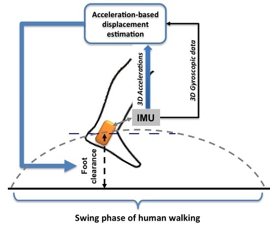
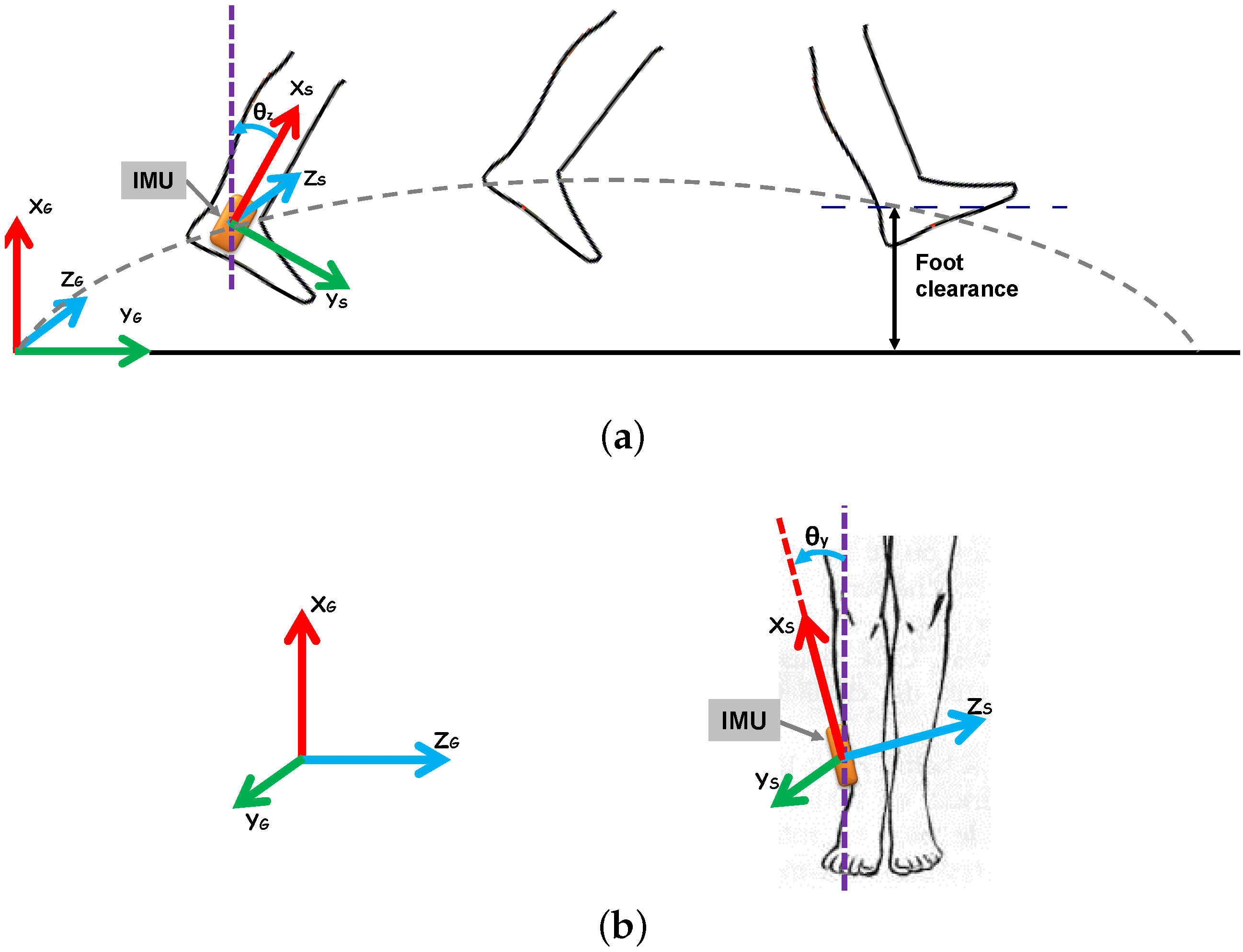
Figure 1 shows sagittal and frontal views of IMU placement for foot clearance estimation (FCE). Possible misalignment of the IMU with respect to the vertical axis is also illustrated (
Figure 1b). As mentioned earlier, we defined foot clearance as the continuous heel clearance (
Figure 1a). Estimation of ankle joint clearance (where the IMU is placed) is adequate, since there is only one bias to be added, corresponding to the distance between IMU-based estimated clearance and heel clearance. Moreover, this ankle joint clearance is most appropriate in the context of drop foot correction [
4].
Figure 1.
IMU placement and frame transformation in (a) the sagittal view and (b) the frontal view.
Figure 1.
IMU placement and frame transformation in (a) the sagittal view and (b) the frontal view.
Figure 2.
IMU-based foot clearance estimation algorithm.
Figure 2.
IMU-based foot clearance estimation algorithm.
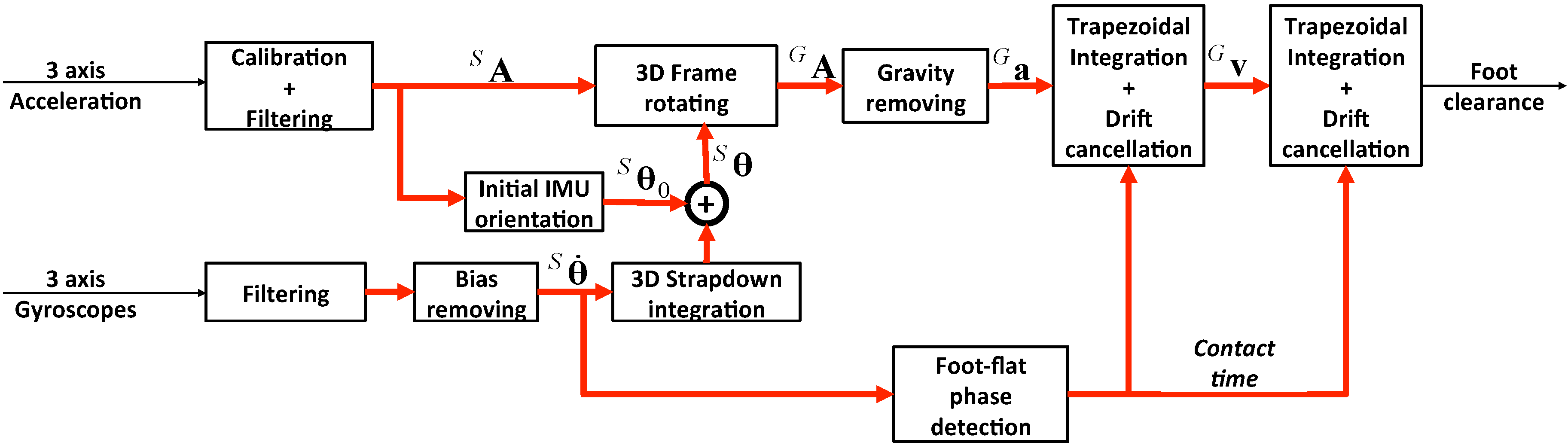
The proposed FCE algorithm (illustrated in
Figure 2) uses only acceleration in the global frame. However, since acceleration is measured in the sensor frame, gyroscope-based angular rate data are used to estimate foot acceleration in the global frame. Each step of the method is detailed below.
2.1. Accelerometer Calibration
An efficient calibration procedure is essential for ensuring accurate accelerometer-based acceleration measurement. The proposed calibration procedure is based on a previous study [
25] and consists of optimizing the three-axis accelerometer output, such that, under stationary conditions, the norm of the acceleration vector is equal to the norm of the gravity vector (
i.e.,
m/s
). For this purpose, the IMU sensor was placed in N (>20) different random orientations, and each corresponding acceleration vector was measured under static conditions. The mathematical model of calibrated accelerometer output is described as follows [
25]:
where
is the calibrated acceleration,
is the measured acceleration prior to calibration and
and
are, respectively, the scale matrix and bias vector identified during the calibration procedure.
and
were identified using a Newton iterative optimization algorithm that minimizes quadratic errors between the norm of the calibrated acceleration vector and the norm of the gravity vector for each static orientation. This calibration was performed once, and the resulting calibration matrices (
,
) were used to correct measured acceleration data (
Figure 2) using Equation (
1).
2.2. Data Filtering and Bias Removing
Since IMU data were post-processed offline, there were no real-time constraints. We therefore chose a data acquisition frequency of 200 Hz. However, frequency sampling should be optimized for future real-time applications, so as to ensure sufficient measurement quality and compliance with real-time constraints.
Three-axis gyroscope data were band-pass filtered between 0.001 Hz and 5 Hz using a first-order Butterworth filter to remove constant and high frequency components. The angular rate in the stationary state (subjects were asked to remain static at the start of each trial) was considered as a bias and, therefore, automatically detected, quantified and removed from the entire gyroscope signal. For three-axis acceleration data, a first-order low-pass Butterworth filter with a 10-Hz cutoff frequency was applied to remove high-frequency noise. However, the bias was not subtracted from the acceleration signal at this stage, since it corresponds to the gravity acceleration, which changes according to IMU orientation.
2.3. Gyroscopic Data Integration
As illustrated in
Figure 2, processing of gyroscopic data is crucial for processing of gravity-free acceleration (due to the movement only), since the measured acceleration also includes the gravity effect. Therefore, proper processing and integration of gyroscopic data was required to expect proper acceleration-based displacement estimation (
Section 2.4).
The filtered angular rate
(see
Figure 2) was then integrated using a 3D strapdown integration method [
11,
26]. This integration method has the advantage of considering rotations around all three axes, since IMU rotation exclusively in the sagittal plane cannot be ensured during walking. This is based on a recursive equation (Equation (
2)) that updates the 3D orientation matrix of the IMU:
where
is the 3D orientation matrix in the global frame at sample
i, the initial transformation matrix
is the identity matrix (
I),
is the time interval between two successive samples (
,
i) and
is the angular rate vector at sample
i.
is the skew-symmetric matrix representing the cross-product operator, such that:
where
,
,
are the elements of
.
At each time instant, the transformation matrix represents the IMU frame transformation with respect to the initial IMU configuration. In practice, IMU orientation is never absolutely vertical in the initial position, and as a result, the initial frame is not the global frame. Therefore, in order to define the transformation matrix with respect to a global frame independently of initial placement, we made the initial matrix equal to a transformation matrix between the initial IMU position and the global frame (vertical orientation).
This initial transformation matrix consists of a rotation about the Z-axis (pitch) with an angle of
, followed by another rotation about the Y-axis (roll) with an angle of
, where the sign of rotation is as shown in
Figure 1. This initial transformation matrix is therefore defined as follows:
where
and
were estimated based on the projection of the gravity vector on the three axes [
11], measured by accelerometers during the stationary period,
i.e., prior to the start of movement. Considering the order of rotation defined above (Equation (
4)), these initial angles (tilt angles) were calculated using the following equations:
where
is the gravity vector measured on the three IMU axes during the stationary period. Based on our measurements, the drift in gyroscopic data integration was neglected, and as a result, no drift cancellation was required at this level.
2.4. Displacement Estimation
The proposed displacement estimation method is based on double integration of foot acceleration data on the global frame axes. To achieve this objective and thereby overcome the integration drift problem, the following steps are applied.
2.4.1. 3D Frame Transformation and Gravity Removing
It is well known that IMU-based acceleration measurements correspond to the acceleration in the sensor frame, whereas the useful acceleration should be the acceleration with respect the global frame. Moreover, the measured acceleration includes gravitational acceleration, which should be removed to obtain gravity-free acceleration due to movement only. Therefore, the acceleration in the sensor frame
was first transformed to the global frame (
in
Figure 2) using the strapdown transformation matrix (Equation (
2)):
Gravitational acceleration was then removed to obtain the gravity-free acceleration in the global frame
:
To obtain the vertical foot displacement (foot clearance), the vertical component of the gravity-free acceleration
needs to be integrated twice (Equation (
7)).
2.4.2. Foot-Flat Phase Detection
One of the main problems with the integration of acceleration data is the significant integration drift, which is further increased by double integration. The proposed solution to overcome this problem is an adaptation of the ZVU principle [
27]. The proposed ZDU principle consists of detecting when the foot is flat on the ground and setting the vertical velocity and displacement to zero. These particular events are detected by the foot-flat phase detection algorithm (illustrated in
Figure 2), which uses the angular rate about the Z-axis (
) to automatically detect when the foot is flat on the ground [
20,
28]. Such events are detected based on the detection of the minimum angular velocity at each stride cycle. This foot-flat phase corresponds to the period of time between heel-strike and heel-off.
2.4.3. Drift Cancellation
The foot-flat phase detection algorithm segments walking into several strides. This segmentation avoids the accumulation of drift error between different strides. However, at the end of each stride, a local drift (occurring only during a current stride) appears as an error between integrated and theoretical data, corresponding to the foot-flat phase. In the proposed method, we applied a drift cancellation on the vertical foot velocity for each stride, based on the error accumulated at the end of each stride and the zero vertical velocity assumption. This correction used the following model [
19]:
where
is the vertical foot velocity obtained using trapezoidal integration of gravity-free acceleration on the X-axis (
),
is the calculated velocity at the end of the stride phase,
t is the time instant of the current stride,
T is the entire duration of the current stride and
is the vertical foot velocity after correction for the entire stride phase.
To estimate the vertical foot displacement (foot clearance), we first integrated the driftless corrected vertical velocity (
) and then applied the same drift cancellation on this vertical foot displacement, assuming zero foot clearance at the end of the stride (foot-flat phase). This second correction used the following model:
where
is the vertical foot displacement obtained by trapezoidal integration of the corrected velocity
,
is the calculated displacement at the end of the stride phase and
is the vertical foot displacement after correction during the stride phase, corresponding to the estimated foot clearance.
Since the drift cancellation was applied during the swing phase, the foot clearance was set to zero during the foot-flat phase in agreement with our assumptions.
3. Experimental Validation
For validation of our foot clearance estimation method, an experimental procedure was applied on both feet of ten healthy participants whose characteristics are summarized in
Table 1 below.
Table 1.
Characteristics of study participants.
Table 1.
Characteristics of study participants.
| Subject Number | Age (Years) | Height (m) | Sex (M/F) |
|---|
| 1 | 35 | 1.85 | M |
| 2 | 24 | 1.89 | M |
| 3 | 40 | 1.60 | F |
| 4 | 23 | 1.55 | F |
| 5 | 23 | 1.71 | F |
| 6 | 29 | 1.93 | M |
| 7 | 26 | 1.72 | M |
| 8 | 26 | 1.62 | F |
| 9 | 24 | 1.76 | M |
| 10 | 23 | 1.58 | F |
Two IMU sensors (HikoB Fox©Villeurbanne, France) were strapped to both feet of each subject (at the ankle joint), as shown in
Figure 3.
Each subject stood upright, remained still for a few seconds and then walked a distance of approximately 10 m on flat horizontal ground. Each subject covered this distance four times walking normally, four times walking fast and two times crossing obstacles. The fast walk was to test a higher level of acceleration and then to increase the drift level. The purpose of walking with obstacles was to test the estimation of a higher level of clearance and nonsymmetrical and nonperiodic walking. The obstacle heights range from 20 cm to 50 cm and were placed to influence normal walking, increase the foot clearance and test the robustness of our estimation method. As illustrated in
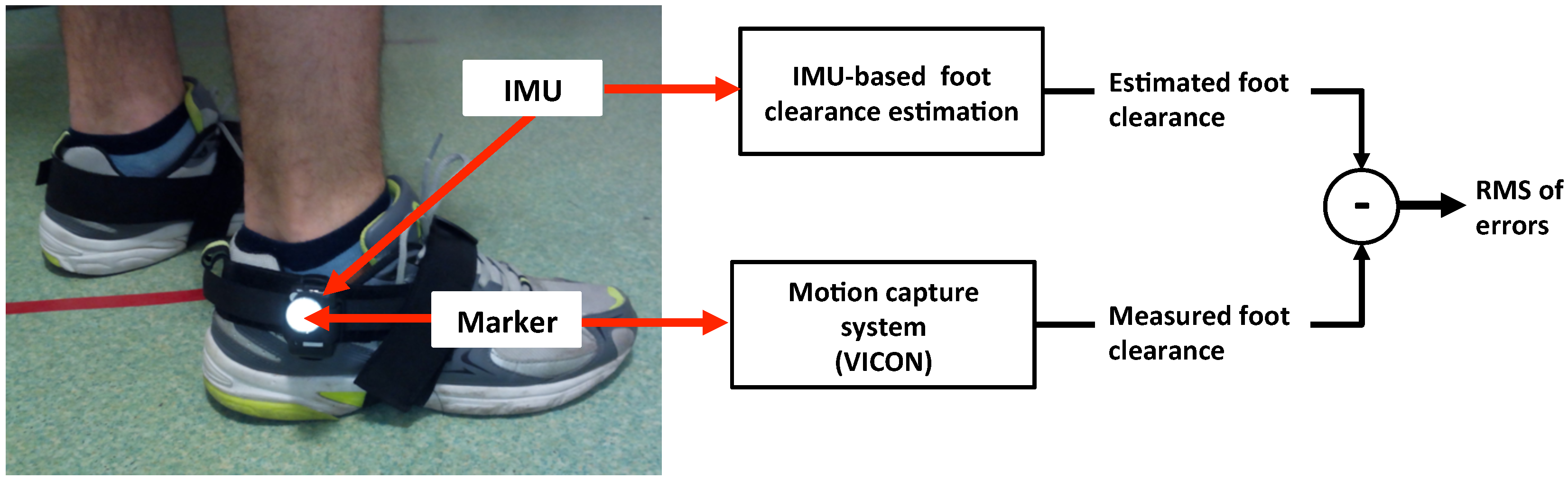
Figure 3, foot clearance estimation was validated with a BONITA VICON motion capture system, using reflective markers located on the IMUs.
Figure 3.
Experimental setup and validation of IMU-based foot clearance estimation.
Figure 3.
Experimental setup and validation of IMU-based foot clearance estimation.
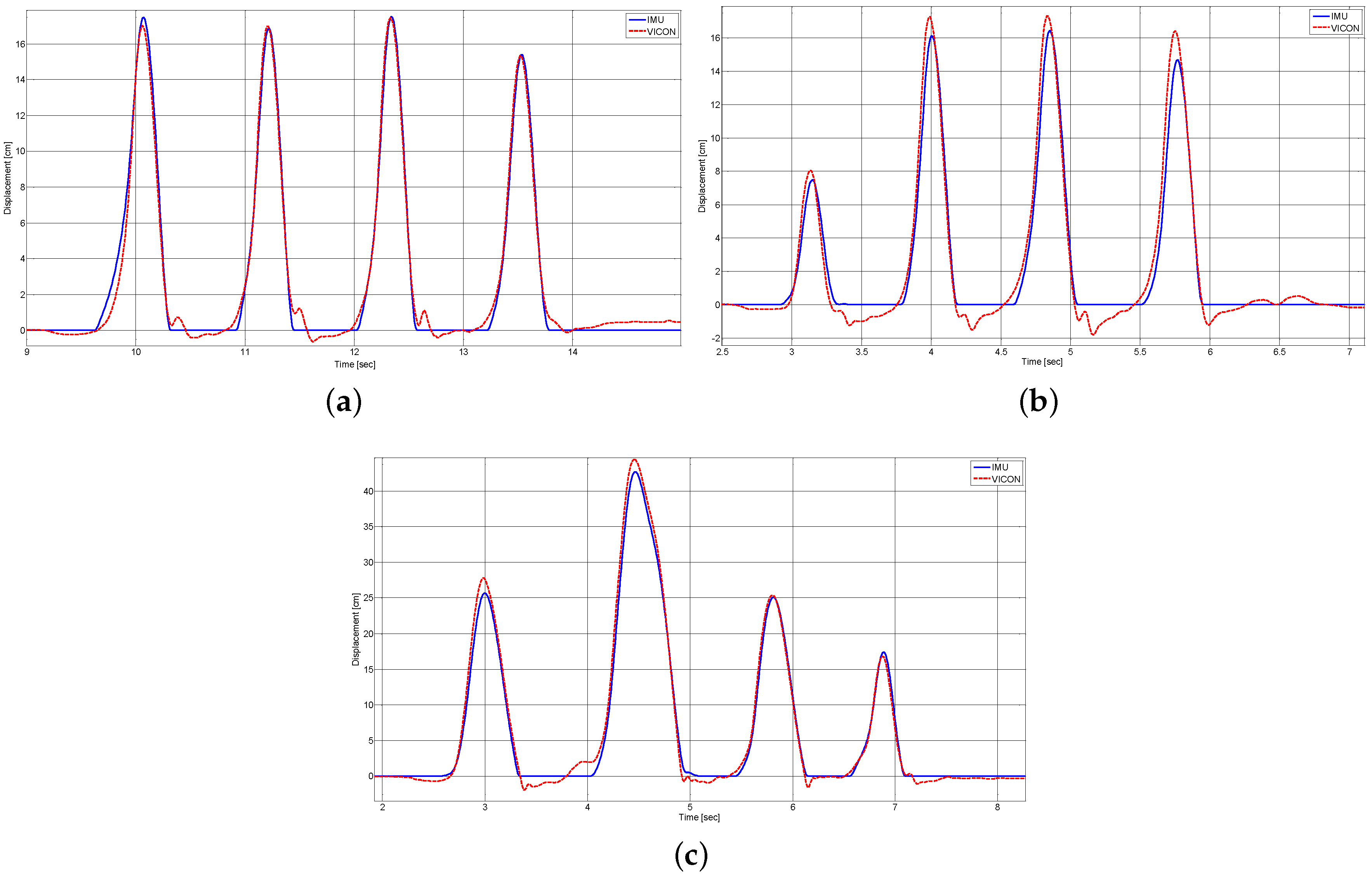
Measured and estimated peak foot clearance values were automatically detected and used to synchronize the two datasets. Foot clearance data for the entire movement, measured with the motion capture system and estimated using the proposed method, was then compared (
Figure 3). Subsequently, the RMS value of foot clearance errors (
) was quantified for the evaluation of foot clearance estimation performance, using the following criterion:
where
and
are respectively the measured and estimated foot clearance, discretized to
Nsamples throughout the walking cycle duration. This number of samples (
N) was associated with the walking cycle duration and discretization (sampling) frequency,
i.e., approximately 200 Hz for both VICON and IMU signals.
To compare the foot clearance estimation performance under different walking conditions, it was necessary to calculate another error criterion, since foot clearance values obtained during walking with obstacles were three-times higher than during normal walking. A normalized RMSE percentage value was therefore calculated for each subject and walking type by normalizing the RMSE with respect to the maximum foot clearance during the current walking test as follows:
5. Conclusions
In the present work, a single mounted inertial measurement unit (IMU) was used to estimate the foot clearance, from the double integration and de-drift correction of acceleration. An original algorithm of foot clearance estimation is proposed, which is robust to misalignment of IMU axes with respect to the foot axes. Our foot clearance estimation method was validated on both feet of 10 healthy subjects, with different sizes and gaits (normal walking, fast walking and walking with obstacles). For this experimental validation, an optical measurement of IMU position through a motion capture system was used as the reference. Then, the deviation between the IMU-based foot clearance estimation and the one measured with the motion capture system was quantified and discussed.
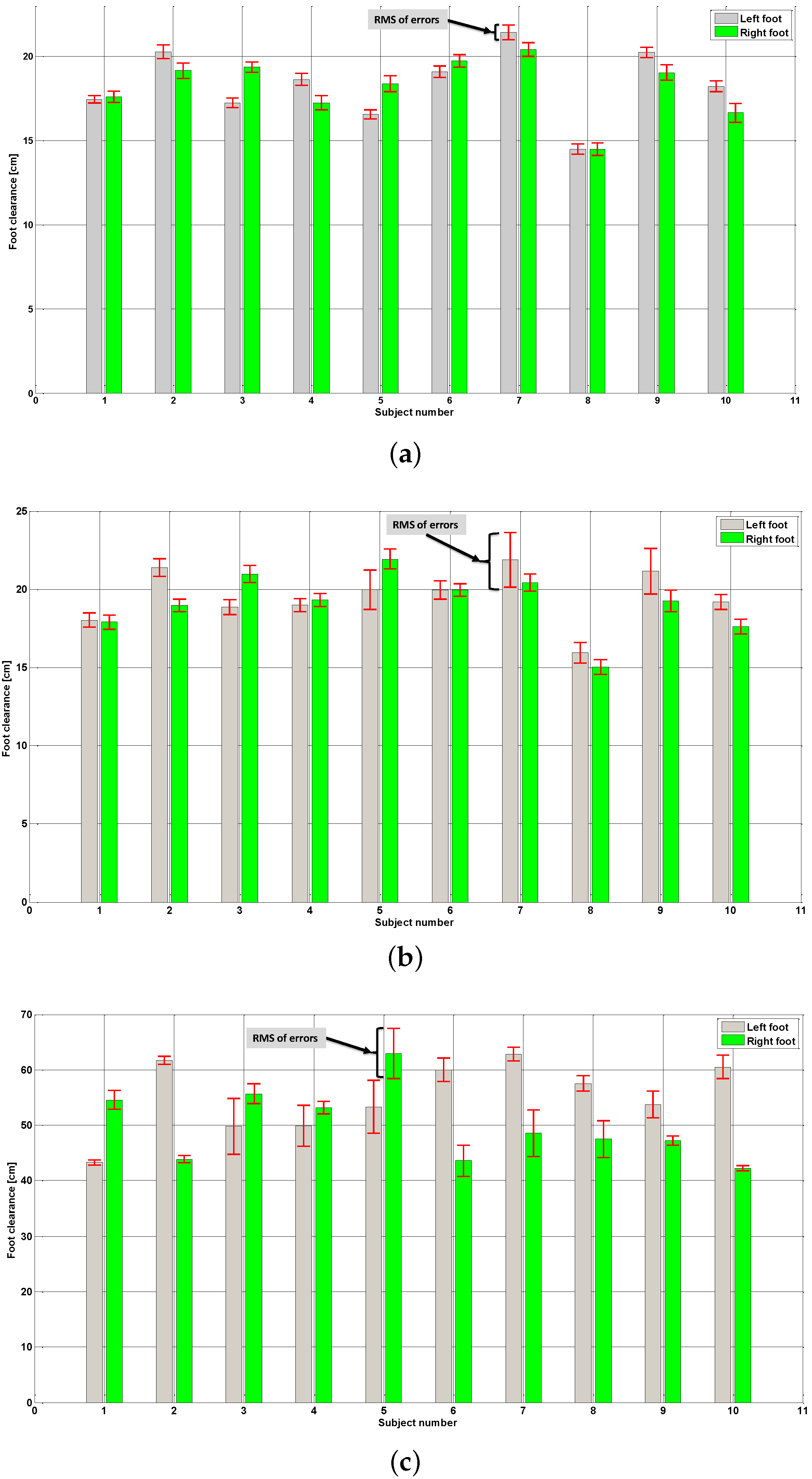
Experimental validation results obtained for all subjects showed good foot clearance estimation performance, where the average of all normalized RMSE values, including all walking types, is approximately , which corresponds to 1.3 cm, if the maximum foot clearance is approximately 20 cm.
Detailed results showed the best estimation performance during normal walking, with an average of RMS error around 0.74 cm, where this average of RMS errors is around 1.3 cm in the case of the fast walking. This performance degradation can be due to the limitation of acquisition frequency in the presence of a higher acceleration. The results obtained during walking with obstacles show a decrease in estimation performance, even when normalized with a higher foot clearance than for other walking types. However, even in this case, the average of normalized RMS errors in of experiments is approximately , which presents a good estimation performance. This performance loss can be due to a decrease of segmentation walking accuracy, since this walking type is not as usual and periodic as normal and fast walking types.
Our foot clearance estimation method was performed offline, since IMU data were acquired locally on the SD card of the sensor. Regarding potential prospects for IMU wireless data transmission, an adaptation of this method will be required for an online version of the proposed foot clearance estimation algorithm.
Some of the proposed algorithms are included in a Python toolkit devoted to developments regarding acquisition, analysis and visualization of IMU-based motion capture. Open access to this toolkit is available via the link [
29].


