
An Intelligent System Proposal for Improving the Safety and Accessibility of Public Transit by Highway

 ,
,
Abstract
:
1. Introduction
2. Related Studies

| Special Needs User Type | Required Intelligent Services |
|---|---|
| Users with limited mobility (require a wheelchair or assistance to walk, cannot use fingers or arms, coordination problems, limited strength). | Systems to assist in boarding and disembarking from the vehicle. |
| Alert system in adapted vehicles. | |
| Traveler information systems with adapted terminals. | |
| Adapted wireless payment systems. | |
| Users with visual impairment. | Systems to assist in boarding and disembarking from the vehicle. |
| Route assistant. | |
| Adapted wireless payment systems. | |
| Users with hearing impairment. | Mobile device-based information systems based on visual perception. |
| Users with cognitive impairment. | User-friendly traveler assistant that provides simple and easy to understand information. |
3. Objectives
4. Description of the System
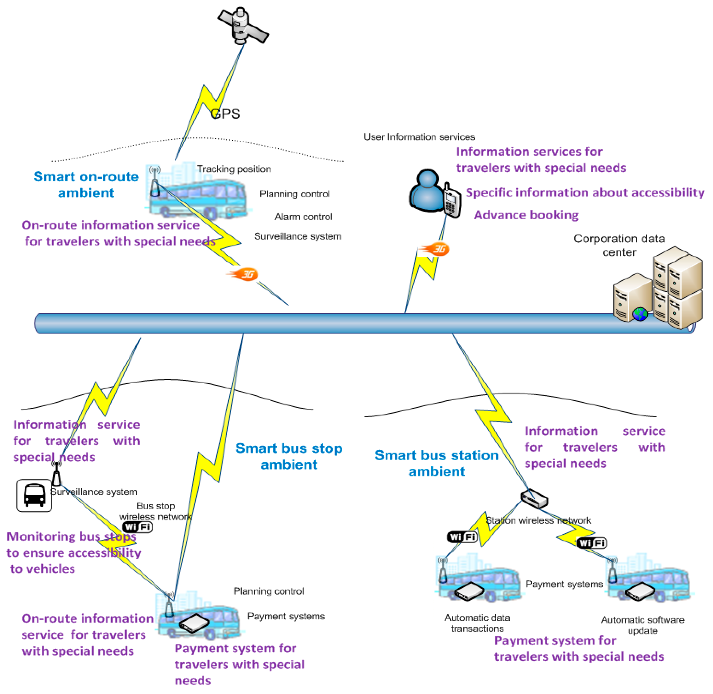
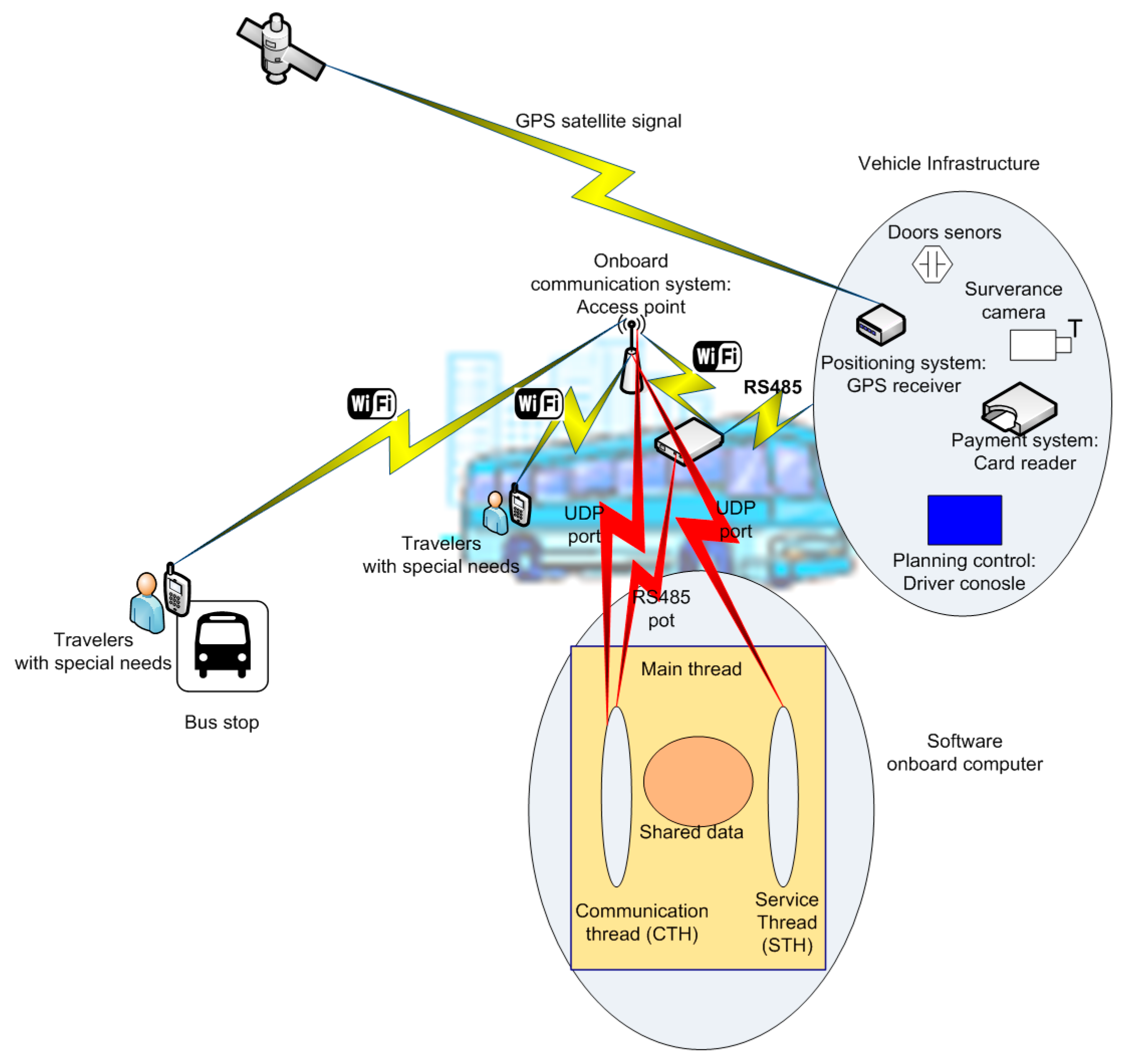
4.1. Infrastructure Components
- Vehicle positioning system. The positioning system that is most commonly utilized in public transit vehicles is the global positioning system (GPS). This system provides the geographic coordinates of a vehicle (latitude, longitude, and elevation), its measurement quality, and the moment in which it was acquired in coordinated universal time (UTC). The measurements provided by this system may contain errors due to different factors, such as environmental conditions (in the ionosphere and atmosphere), the curvature of the surface of the Earth, shadowed areas that do not enable signals from satellites to be detected, or a random error introduced by the system. A conventional system is assumed to provide measurements with a maximum error of 100 m when the measurement quality is sufficient, which is obtained when the GPS receiver is able to acquire the signal from a minimum of four satellites.
- Communications system. To permit data communications with vehicles, highway public transit companies utilize mobile communication systems, such as General Packet Radio Service (GPRS) or UMTS (3G or 4G) for long-distance communication, Institute of Electrical and Electronics Engineers (IEEE) 802.20 (iBurst) for urban areas, and IEEE 802.11 (WI-FI) for communications at stations. Recently, short-distance communication technologies, such as IEEE 802.15.1 (Bluetooth), IEEE 802.15.4 (ZigBee), or radio-frequency identification (RFID) have been utilized to provide personalized services to people with special needs in different contexts of mobility, such as public transit.
- On-board sensors. To improve vehicle security, vehicles are equipped with open-door sensors. These sensors are used to prevent a vehicle from moving when passengers are entering or exiting the vehicle. In addition, open-door sensors are utilized to activate payment terminals located at the entry and exit points of vehicles. Open-door sensors are connected to the vehicle infrastructure via an electrical connection panel, where the signals from detectors at the end of the carriage assembly of each door are located; from this panel, they are connected to the digital inputs of the payment terminals. When a door is closed, its sensor is in a closed state (normally closed is coded as a logical 0), whereas this state changes to an open state (logical 1) at the moment the door begins to open.
4.2. Incorporation of New Components
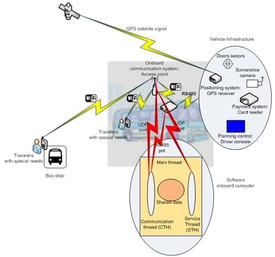
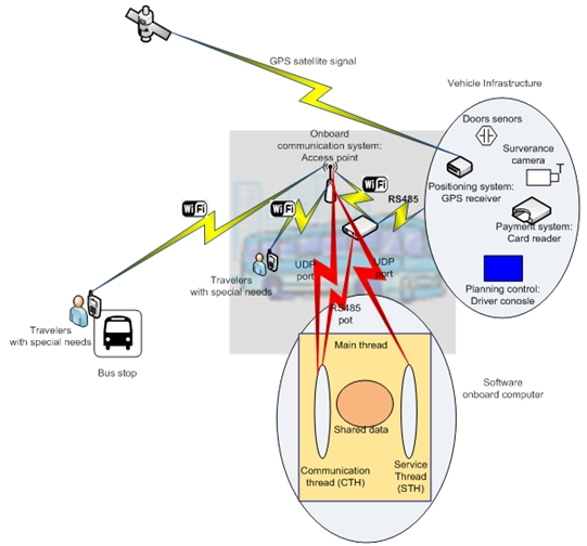
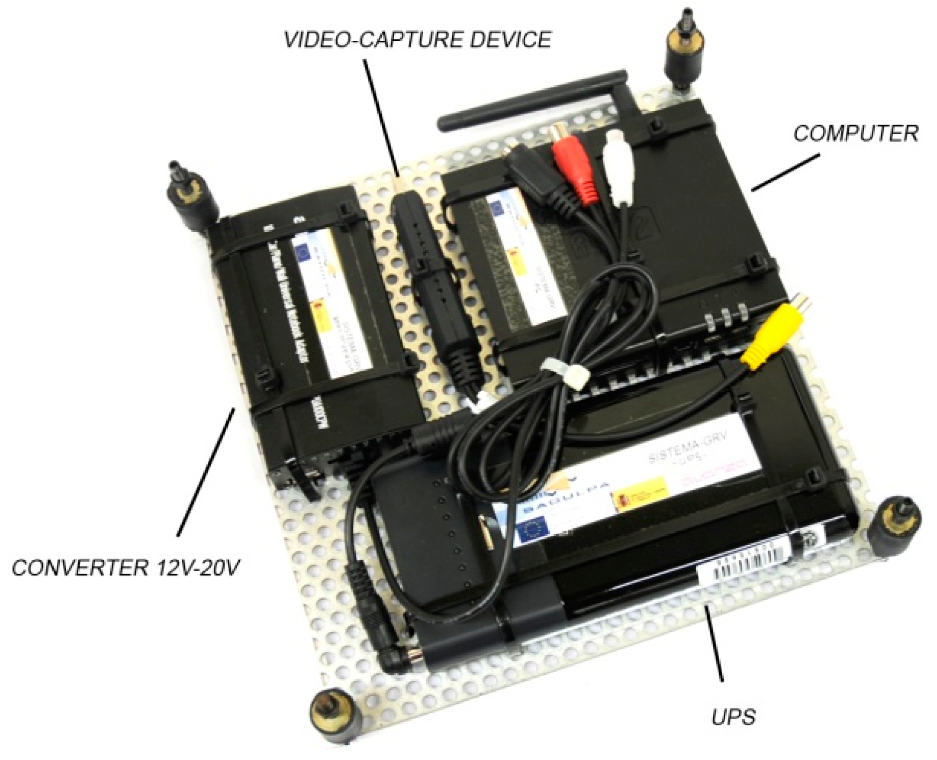
4.2.1. On-Board Computer (OBC)
- The main thread (MTH) that initiates with system start-up and is executed in an uninterrupted manner. This thread creates the remainder of the threads that are executed in the system and the required communication channels.
- Vehicle infrastructure communication thread (CTH). This thread is the first thread created by MTH and executed in an uninterrupted manner. The mission of this thread is to communicate with the vehicle infrastructure to obtain the data required by the services that are provided en route. These data are stored in an area of shared memory to ensure access by the remainder of the threads.
- Service threads (STH). These threads provide various services en route and obtain the data required by the various services; when necessary, they will transmit the data to the mobile devices of travelers.
- Communications system: UMTS technology (3G) for short data communications relating to operations and alarms control events in the vehicles. Wi-Fi technology for data communications that require higher bandwidth, e.g., to transfer production data generated in the vehicles, synchronize the databases stored on the vehicles or even for software updates run on the vehicle. These data communications are performed using the existing Wi-Fi infrastructure at certain points on the transport network, in stations and garages, where vehicles are frequent and stop for a set period of time.
- Positioning system: GPS system. All vehicles are equipped with a GPS receiver that provides the position, speed and a precise clock signal to synchronize all the clock signals used by the various vehicle devices (driver console and contactless card readers).
- Vehicle sensors: sensors to control vehicle temperature, open-door sensors to determine the state of the vehicle doors (open or closed) and cameras to view the vehicle’s passengers enter and exit.
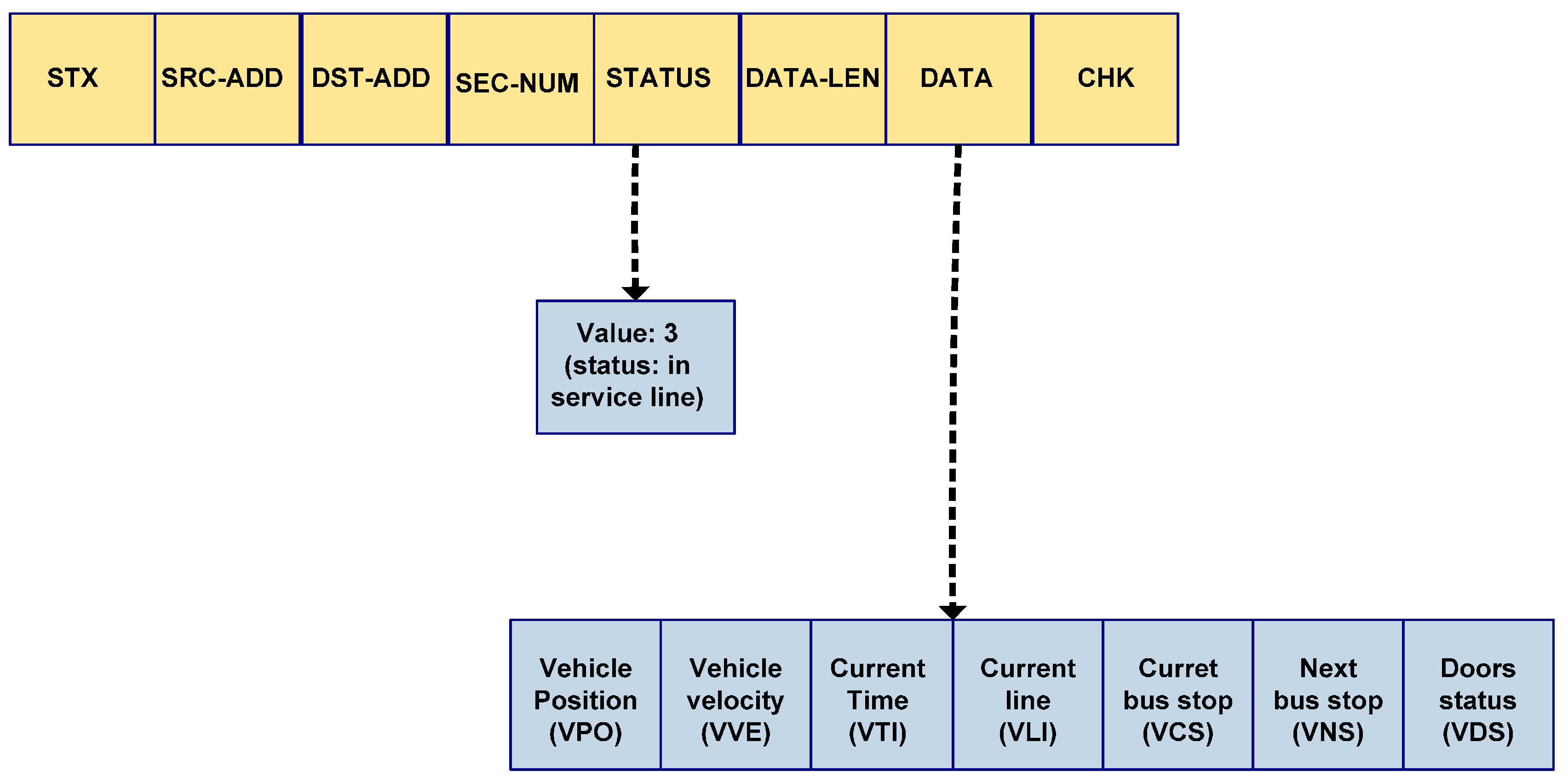
| Field | Field | Field | Field | Field | Field | Field | Field |
|---|---|---|---|---|---|---|---|
| STX | SRC-ADD | DST-ADD | SEC-NUM | STATUS | DATA-LEN | DATA | CHK |
| Special Needs User Type | Resource Infrastructure Required by Services (STH Threads) | Requirements for User Applications (ACli) |
|---|---|---|
| Users with limited mobility (require a wheelchair or assistance to walk, cannot use fingers or arms, coordination problems, limited strength...) |
|
|
| Users with visual impairment |
|
|
| Users with hearing impairment |
|
|
| Users with cognitive impairment |
|
|
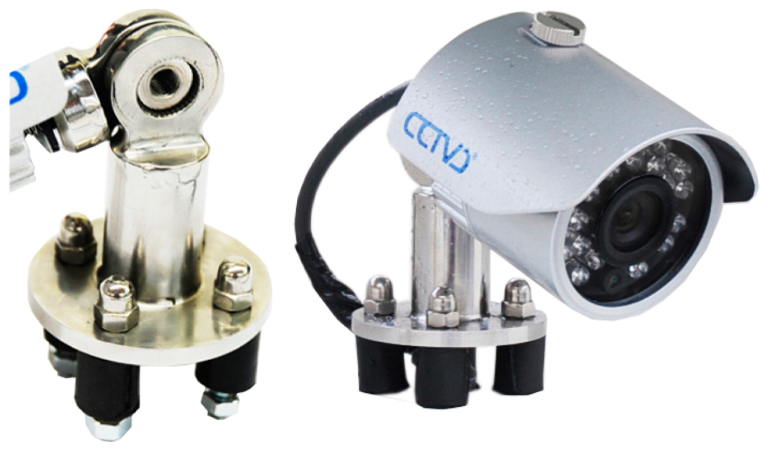
4.2.2. Camera
- Location: in the center of the upper front part of the vehicle, at an elevation that varies between 3.2 and 3.7 m, depending on the model of the bus.
- Viewing angle: 45°.
- Focal length: 8 mm.
- Inclination of the camera: 15°–20°.
- Light sensitivity of the sensor: 0.05 lux (night vision).
- Image resolution: 640 × 480 pixels.
4.2.3. Communication System
| Field | Length | Description |
|---|---|---|
| STX | 1 byte | Start of O×FF data packet |
| SRC-ADD | 1 byte | Identifier of origin node: |
| 0: Master node. | ||
| 1: OBC. | ||
| DST-ADD | 1byte | Identifier of destination node: |
| 0: Master node (MN). | ||
| 1: Slave node (SN). | ||
| SEC-NUM | 1 byte | Packet sequence number: 0–255 |
| STATUS | 1 byte | State of infrastructure/vehicle operation: |
| 0: Infrastructure out of service. | ||
| 1: Error in the infrastructure. | ||
| 2: Vehicle out of service. | ||
| 3: Line in service state. | ||
| 4: End of line service. | ||
| 5: Forced termination of communication with infrastructure. | ||
| 6: Packet correctly received. | ||
| 7: Erroneous data packet. | ||
| DATA-LEN | 1 byte | Number of bytes in the data field. |
| DATA | Value of the DATA_LEN field | Data field whose structure is dependent on the status (STATUS field). |
| CHK | 1 byte | Byte of checksum for error control in the data packet. |
- If this length of time passes without a response, then the message is repeated for a maximum number of tries (NT). If the value of NT is attained, the infrastructure assumes a failure in the system and a record and notification of this incident is generated.
- A response is received from the SN; if the STATUS field of the received packet as a value of 6 and the SEC-NUM field coincides with the transmitted packet, the packet has been correctly received by the SN. If the received packet contains a value of 7 in the STATUS field, it indicates that the packet with the number sequence equal to the SEC-NUM field has been received with errors, which causes the MN to resend the packet.
5. Use Cases
- Record of the vehicle’s GPS position every second (latitude, longitude, elevation, speed, quality of the measurement, when it was acquired).
- Record of vehicle operations and when they were carried out: when service commenced, when the line started operating, stops, travelers’ journey payments, when the line stops, end of service.
- Record of technical alarms associated with the on-board devices and at what time they occurred.
- Record of planning irregularities: failures in line service commencement and stop times, full vehicle warning.
- Correct provision of required data from the infrastructure to the OBC. We checked that the OBC has all the data needed to represent the state of the vehicle at all times.
- Correct provision of data required by each type of ACli application developed. We checked that the ACli client application has all the necessary data to provide accurate and useful information to the user.
- Communication protocol latency between the infrastructure and the OBC. For changes in the state of the vehicle and the OBC, we measured the time elapsed from the moment the change of state occurs at one end (infrastructure or OBC) until it is received by the device at the other end.
- Response times in the interactions between the OBC and the client application. For changes in the state of the vehicle and the client application, we measured the time elapsed from the moment the change of state occurs at one end (OBC or client application) until it is received by the device at the other end.
- Response time of the client application. We measured the time required to display the information to the user according to their preferences.
- Failure of any infrastructure component.
- OBC failure.
- Failure of communication with the OBC.

5.1. Accessibility Surveillance System at Stops
- A risk for passengers, given that they must enter the thoroughfare on occasion.
- An inconvenience because they must move outside the vehicle access area, carry luggage, and accompany children or people with mobility problems. Parking outside of the parking area at stops may create access mechanisms for people with mobility problems, e.g., access ramps do not deploy, which impedes access to these travelers.
- Decreased commercial speed given that the vehicle must perform complex maneuvers for parking, which enables passengers to board and disembark.
- Interrupts the circulation of other vehicles, given that they must park by entering the thoroughfare, which increases the risk of accidents.
- Start of acquisition: Image acquisition is automatically activated when the vehicle is near the next stop on the route. The proximity is expressed by the distance threshold D, which is associated with each stop along the route. Proximity is obtained by calculating the distance between the current position and the geographical point of the stop; when the distance is less than D, the system activates image acquisition. Considering the limitations of measurement accuracy of a conventional GPS, the distance D must not be less than 100 m.
- End of acquisition: Image acquisition is stopped when the vehicle is more than D from the last stop reached by the vehicle. The acquired images are recorded in a file and stored in the OBC.
- Referencing images in space and time: To determine where and when the images were acquired, each file is referenced by geography and time (date and time) using data from vehicle positioning.
- Transfer of image files: When a vehicle makes a scheduled operating stop in a place with Wi-Fi infrastructure (stations, main stops, or garages), the video files are transferred to the image repository of the company.
Study of the Performance of the Accessibility Surveillance System at Stops
- Resolution. The resolution must provide sufficient image quality to obtain the required information. In our case, the plate number of the vehicle must be visible. The camera offers several resolutions, which range from 176 × 120 to 720 × 480 pixels. A resolution of 640 × 480 is a suitable resolution for the tests.
- Method of compression. Compression reduces the space that is required to store an image sequence and reduce the bandwidth that is required to transmit an image file over the wireless network. Three compression methods were tested: H.260, MPEG-4, and Motion JPEG. We opted for the latter because it is the latest method and offers significant savings in space, namely, compression was performed with 25 frames/s and a resolution of 640 × 480 pixels. With these parameters, the compression of a sequence of images with a length of 1 s requires approximately 34.13 Kbytes of storage space.
- Storage requirements for a route. Considering the findings of these tests, the problem consists of estimating the space required for a bus route. According to the previously described system operation, the image sensor is activated when a vehicle is located at a distance of less than or equal to 100 m from the next stop and automatically turns off when the vehicle is located at a distance that is equal to or greater than 100 m from the last stop. Therefore, the acquisition time at a stop is dependent on the time required to travel 200 m around the stop, including the time that the vehicle is stopped for passengers to embark and disembark from the vehicle. To obtain precise information, detailed tracking of a bus has been performed to record the position data of the vehicle (latitude, longitude, elevation, speed, quality of measurement, and instant the measurement was taken) at each second over a long period of time (one month). These records were stored in a database that also contained records of the operations performed by the vehicle. Because these operations records are referenced in time, the time periods during which the vehicle performed programmed trips and the route identification were obtained. After obtaining these periods and noting the geographical coordinates of each route stop, the positioning records obtained during these periods were analyzed by selecting the sets of positioning measurements located within 100 m around each of the stops along the route. For each set, the time instant (T0) when the first positioning measurement was acquired and the time T1 when the last measurement of the set was acquired were obtained, where the estimated space required for each set was (T1 − T0) × 34.13 Kbytes. Table 5 lists the results for the selected route stops. This route has 28 stops in both urban and rural areas. The table lists the identifier of each stop, which coincides with its position in the route order (column 1), the maximum travel time for traversing 200 m around the stop (column 2), and the estimated space required for storing the sequence of images acquired during this maximum time period (column 3). Estimation of the space required to store the image sequence of each stop in the line is 108.75 Mbytes.
- Performance of the communications system. In order to assess the performance of the communications system we have only analyzed the time required to transmit the images. We have not analyzed how the mobility of the vehicles affects the transmission error rate because these transmissions are made when the vehicle is stationary. Image transmission is performed when vehicles are in places with Wi-Fi coverage, namely stations and garages. In general, these places are open-plan, i.e., they contain no obstacles that hinder communications. Considering the available bandwidth of the Wi-Fi infrastructure (802.11 g), with speeds in outdoor open environments ranging from 54 Mbit/s in a radius of 75 m to 6 Mbit/s in a radius of 400 m, the estimated transmission times for image files of various sizes are shown in Table 5.
| Stop | T. Max (s) | Estimated Maximum Required Storage Space (KBytes) | 54 Mbits/seg 75 m (s) | 24 Mbits/seg 140 m (s) | 6 Mbits/seg 400 m (s) |
|---|---|---|---|---|---|
| 1 | 86 | 2935.18 | 0.4 | 1.0 | 3.8 |
| 2 | 53 | 1808.89 | 0.3 | 0.6 | 2.4 |
| 3 | 100 | 3413 | 0.5 | 1.1 | 4.4 |
| 4 | 176 | 6006.88 | 0.9 | 2.0 | 7.8 |
| 5 | 56 | 1911.28 | 0.3 | 0.6 | 2.5 |
| 6 | 93 | 3174.09 | 0.5 | 1.0 | 4.1 |
| 7 | 40 | 1365.2 | 0.2 | 0.4 | 1.8 |
| 8 | 64 | 2184.32 | 0.3 | 0.7 | 2.8 |
| 9 | 37 | 1262.81 | 0.2 | 0.4 | 1.6 |
| 10 | 48 | 1638.24 | 0.2 | 0.5 | 2.1 |
| 11 | 328 | 11,194.64 | 1.6 | 3.6 | 14.6 |
| 12 | 214 | 7303.82 | 1.1 | 2.4 | 9.5 |
| 13 | 251 | 8566.63 | 1.2 | 2.8 | 11.2 |
| 14 | 409 | 13,959.17 | 2.0 | 4.5 | 18.2 |
| 15 | 201 | 6860.13 | 1.0 | 2.2 | 8.9 |
| 16 | 261 | 8907.93 | 1.3 | 2.9 | 11.6 |
| 17 | 50 | 1706.5 | 0.2 | 0.6 | 2.2 |
| 18 | 67 | 2286.71 | 0.3 | 0.7 | 3.0 |
| 19 | 238 | 8122.94 | 1.2 | 2.6 | 10.6 |
| 20 | 19 | 648.47 | 0.1 | 0.2 | 0.8 |
| 21 | 46 | 1569.98 | 0.2 | 0.5 | 2.0 |
| 22 | 14 | 477.82 | 0.1 | 0.2 | 0.6 |
| 23 | 31 | 1058.03 | 0.2 | 0.3 | 1.4 |
| 24 | 61 | 2081.93 | 0.3 | 0.7 | 2.7 |
| 25 | 133 | 4539.29 | 0.7 | 1.5 | 5.9 |
| 26 | 65 | 2218.45 | 0.3 | 0.7 | 2.9 |
| 27 | 29 | 989.77 | 0.1 | 0.3 | 1.3 |
| 28 | 40 | 1365.2 | 0.2 | 0.4 | 1.8 |
| TOTAL | 109,557.3 | 15.9 | 35.7 | 142.7 |
5.2. Route Assistant for Travelers with Special Needs
- User Profile—This datum indicates the type of traveler that is using the application; in this case, the traveler is a blind person. This datum is stored by the ACli application and sent to the STHi thread.
- Details of the trip the traveler wishes to make, which consists of the line identifier (PLI), the origin stop (POS) and the destination stop (PDS)–These data are transmitted to the STHi thread by the ACli application.
- Current vehicle position—This information consists of the geographical coordinates of the vehicle (VPO), the velocity (VSL) and the time point (VTI) in which the position was acquired. These data are provided by the infrastructure of the vehicle (positioning system), transmitted by the OBC, received by the CTH thread and stored in the shared memory for transmission to the ACli application by the STHi thread.
- Line (VLI)—This datum indicates the programmed bus route provided by the infrastructure of the vehicle (control system operations), which the OBC transmits and the CTH thread receives and stores in the shared memory for the STHi thread to transmit to the ACli application. The infrastructure also provides the number of stops of the route (VNS).
- Current Stop (VCS)—This datum indicates at which stop the vehicle is located if it is paused at a stop or the last stop it passed, if it is not at a standstill. This information is provided by the infrastructure of the vehicle (control system operations), which the OBC transmits and the CTH thread receives and stores in the shared memory for transmission by the STHi thread to the ACli application. The position of the current stop is also provided by the infrastructure (VIS).
- Next stop along the route (VNS)—This datum indicates the next route stop and the estimated time of arrival (VTS). This datum is provided by the infrastructure of the vehicle (control system operations), transmitted by the OBC, received by the CTH thread and stored in the shared memory for transmission to the ACli application by the STHi thread.
- State of vehicle doors (VDS)—This datum indicates whether the passenger access doors of the vehicle are open or closed. This information is provided by the infrastructure of the vehicle (vehicle door sensors), transmitted by the OBC transmits, received by the CTH thread and stored in the shared memory for transmission to the ACli application by the STHi thread.
- The actor domain. All concepts related to intermodal transit network actors belong to this domain. The main actors are the travelers, transit operators and transit authorities, and the main actor functions are infrastructure, service and infrastructure provider, and service consumer.
- The infrastructure domain. Concepts related to basic resources for the implementation of information services in a ubiquitous context belong to this domain (hardware resources, information service providers and client applications). These resources are: computing, communication, location and sensors. This is the most complex domain of the architecture because the concepts and functions envisaged in this area must ensure interoperability of all the information services. Physically, this domain is deployed in the components of the transit network. The transit company is responsible for this domain and the beneficiaries are the transit operators.
- The service provider domain. Concepts related to different ubiquitous information services, such as payment systems, traveler assistants, and control operations, belong to this domain. The actors responsible for this domain are transit authorities and operators and the beneficiaries may be operating personnel, transit authority personnel and travelers. Specifications concerning technological and functional aspects belong to this domain.
- The information consumer domain. All concepts related to the accessibility, utility and reliability of the ubiquitous client applications belong to this domain. It is therefore a high-level abstraction domain. The actors responsible for this domain are transit authorities and operators and the beneficiaries may be operating personnel, transit authority personnel and travelers.
- Passenger boarding phase. The objective of the system is safe boarding, which occurs when a passenger boards the correct bus under conditions that do not endanger his or her physical safety that is, boarding when the bus is stopped and the access doors are open. This condition is achieved by indicating to the traveler that the vehicle that they selected is the correct vehicle via the data related to the route (PLI and VLI), current stop (VCS) and destination stop (PDS) and indicating when they can proceed to board, which will occur when the vehicle is stopped, using the vehicle speed data (VSL), and when the doors are open by the vehicle door status data (VDS).
- Passenger travel phase. The objective of the system at this stage is to orient a passenger with special needs to provide safe and stress-free travel. The system communicates the last stop of the vehicle (VCS), the next stop (VNS) if the vehicle is stopped at a stop, the existing stop (VCS and VSL), and the number of remaining stops until his or her destination (VNS and VIS) is reached.
- Disembarking phase. The objective of the system in this phase is safe disembarking. The system achieves this objective by alerting the traveler when he or she has reached his or her destination stop (PDS and VCS), that the vehicle has stopped (VVE), and that the exit doors are open (VDS).
Performance of the Route Assistant System
- Bandwidth required by the protocol. The protocol feature that most affects the bandwidth consumed is the length of the frames. The protocol establishes a frame structure whose data field is of variable length, the length depending on the current state of the vehicle. The most demanding scenario arises when the vehicle is on a line service, in which case the frames may have a data field with a length of 256 bytes and a total length of 263 bytes. Taking the routes used by the transit company used to evaluate the system as our reference, the maximum number of frames required to represent the state of a vehicle when it is operating a line service is three frames. Considering the available bandwidth of the Wi-Fi infrastructure (802.11 g), with speeds in open outdoor environments ranging from 54 Mbit/s in a radius of 75 m to 6 Mbit/s in a radius of 400 m, these three frames represent a very small percentage of bandwidth.
- Mobility. 802.11 technology was designed to operate in mobile environments in which the mobile stations do not move at speeds above 10 km/h, which is the speed of a person walking. Strictly speaking this is called roaming and not mobility. Because the speed at which a vehicle approaches a stop is variable and depends on various factors, such as traffic or road type, the behavior of the communications system when considering this aspect varies. To obtain precise data on this aspect of performance, we analyzed the behavior of the communications system when the vehicle approaches a stop located at the main station used by the company that collaborated in the development of this system. This station is located in an urban environment with highly variable traffic on the roads depending on the type of day (working or holiday) and the time of day; for example, traffic is heavy on a business day from 07:00 to 22:00. The results show that transmission error rate oscillates between 5% and 10%.
- Battery consumption. The efficient use of energy is a key technology challenge for any mobile communications technology. In our case, considering the currently available technologies on mobile devices—UMTS (3G or 4G), IEEE 802.15 (Bluetooth) and IEEE 802.11 g (Wi-Fi)—Wi-Fi technology was chosen because it has a greater range and bandwidth than Bluetooth. The choice of Wi-Fi over UMTS was due to power consumption. In both technologies one of the aspects that most affects power consumption is the registration of mobile terminals at infrastructure access points, due to fluctuations in the strength of the signal owing to the mobility of the mobile terminal. These registration changes trigger an exchange of control packets from the respective protocols and fluctuations in signal strength when sending the packages. In the topology of the proposed system’s communications network, the Wi-Fi access points are located in the vehicles. Therefore, from the perspective of signal quality and assuming that the user mostly uses the service when aboard a vehicle, this is the ideal situation: the maximum distance between a mobile terminal and the access point will be the length of the vehicle, which in the case of public transit buses is no longer than 20 m, and the vehicle contains no elements (walls) that attenuate the signal. However, in the case of UMTS access, mobile terminals would use various points of infrastructure access (cell registration) that would cause registration changes and fluctuations in the terminal transmission strength, thus causing the mobile terminal to consume more energy. This superior energy consumption behavior of Wi-Fi technology over UMTS will be further accentuated with the incorporation of 802.11AC technology into mobile terminals, which will further improve energy efficiency.
6. Impact Assessment of the System
7. Conclusions and Future Works
Acknowledgments
Author Contributions
Conflicts of Interest
References
- European Conference of Ministers of Transport (ECMT). Improving Transport for People with Mobility Handicaps. Guide to Good Practice; OECD Publications Service: Paris, France, 1999; pp. 29–45. [Google Scholar]
- Commission of the European Communities. European Transport Policy for 2010: Time to Decide; COM: Brussels, Belgium, 2001; Volume 370. [Google Scholar]
- United Nation Enabled. Available online: http://www.un.org/disabilities/default.asp?id=18 (accessed on 24 February 2015).
- Duvarci, Y.; Yigitcanlar, T. Integrated Modeling Approach for the Transportation Disadvantaged. J. Urban Plan. Dev. 2007, 133, 188–200. [Google Scholar] [CrossRef]
- Raje, F. The impact of transport on social exclusion processes with specific emphasis on road user charging. Transp. J. 2003, 10, 321–338. [Google Scholar] [CrossRef]
- European Conference of Ministers of Transport. Improving Transport Accessibility for All. Guide to Good Practice; OECD Publications Service: Paris, France, 2006; pp. 41–71. [Google Scholar]
- Frez, J.; Baloian, N.; Zurita, G. SmartCity: Public Transportation Network Planning Based on Cloud Services. In Proceedings of 8th Interantional Conference on Ubiquitous Computing and Ambient Intelligence (UCAmI 2014), Belfast, UK, 2–5 December 2014; pp. 365–371.
- U.S. Department of Transportation. Available online: http://safety.fhwa.dot.gov/older_users/ (accessed on 24 February 2015).
- Shaheen, S.A.; Niemeier, D.A. Integrating vehicle design and human factors: Minimizing elderly driving constraints. Transp. Res. Part C 2001, 9, 155–174. [Google Scholar] [CrossRef]
- Mitchell, C.G.B.; Suen, S.L. Urban Travel, Intelligent Transportation Systems, and the Safety of Elderly and Disabled Travelers. J. Urban Technol. 1998, 5, 17–43. [Google Scholar] [CrossRef]
- Jakubauskas, G. Improvement of Urban Transport Accessibility for the Passengers with Reduced Mobility by Applying Intelligent Transport Systems and Services. In Proceedings of the 8th International Conference Reliability and Statistics in Transportation and Communication 2008, Riga, Latvia, 15–18 October 2008; pp. 102–108.
- Sánchez, J.H.; Oyarzún, C.A. Mobile audio assistance in bus transportation for the blind. In Proceedings of the 7th International Conference Series on Disability, Virtual Reality and Associated Technologies with Art Abilitation, Maia, Portugal, 8–11 September 2008; pp. 279–286.
- Ivanov, R. Mobile GPS navigation application, adapted to visually impaired people. In Proceedings of International Conference Automatics and Informatics, Sofia, Bulgaria, 1–4 October 2008.
- Baudoin, G.; Venard, O. Information, communication and localization environment for travelers with sensory disabilities in public transports. In Proceedings of 5th International ICST Conference on Communications and Networking in China (CHINACOM), Beijing, China, 25–27 August 2010; pp. 1–7.
- Zhou, H.; Hou, K.-M.; Zuo, D.; Li, J. Intelligent urban public transportation for accessibility dedicated to people with disabilities. Sensors 2012, 12, 10679–10692. [Google Scholar] [CrossRef] [PubMed]
- Carmien, S.; Dawe, M.; Fischer, G.; Gorman, A.; Kintsch, A.; Sullivan, J.F., Jr. Socio-Technical Environments Supporting People with Cognitive Disabilities Using Public Transportation. ACM Trans. Comput. Hum. Interact. (TOCHI) 2005, 12, 233–262. [Google Scholar] [CrossRef]
- Luna, J.M.; Hervás, R.; Fontecha, J.; Bravo, J. A Friendly Navigation-System Based on Points of Interest, Augmented Reality and Context-Awareness. In Proceedings of 6th Interantional Conference on Ubiquitous Computing and Ambient Intelligence (UCAmI 2012), Vitoria-Gasteiz, Spain, 3–5 December 2012; pp. 137–144.
- García, C.R.; Pérez, R.; Quesada-Arencibia, A.; Alayón, F.; Padrón, G. Pervasive multimedia guidance system for special needs passengers on public transport. EURASIP J. Wirel. Commun. Netw. 2012, 2012, 1–14. [Google Scholar] [CrossRef]
- García, C.R.; Pérez, R.; Lorenzo, A.; Quesada-Arencibia, A.; Alayón, F.; Padrón, G. Architecture of a Framework for Providing Information Services for Public Transport. Sensors 2012, 12, 5290–5309. [Google Scholar] [CrossRef] [PubMed]
- Proto, M.; Bavusi, M.; Bernini, R.; Bigagli, L.; Bost, M.; Bourquin, F.; Cottineau, L.; Cuomo, V.; della Vecchia, P.; Dolce, M.; et al. Transport Infrastructure Surveillance and Monitoring by Electromagnetic Sensing: The ISTIMES Project. Sensors 2010, 10, 10620–10639. [Google Scholar] [CrossRef] [PubMed]
- European Committee Standardization. Reference Data Model for Public Transport; Technical Report CEN TC278; European Committee Standardization: Brussels, Belgium, 2005. [Google Scholar]
- Hervás, R.; Bravo, J.; Fontecha, J. A context model based on ontological languages: A proposal for information visualization. J. Univ. Comput. Sci. 2010, 16, 1539–1555. [Google Scholar]
- García, C.R.; Padrón, G.; Quesada-Arencibia, A.; Alayón, F.; Pérez, R. Ubquitous Data Management in Public Transport. In Proceedings of 6th Interantional Conference on Ubiquitous Computing and Ambient Intelligence (UCAmI 2012), Vitoria-Gasteiz, Spain, 3–5 December 2012; pp. 342–349.
© 2015 by the authors; licensee MDPI, Basel, Switzerland. This article is an open access article distributed under the terms and conditions of the Creative Commons Attribution license (http://creativecommons.org/licenses/by/4.0/).
Share and Cite
García, C.R.; Quesada-Arencibia, A.; Cristóbal, T.; Padrón, G.; Pérez, R.; Alayón, F. An Intelligent System Proposal for Improving the Safety and Accessibility of Public Transit by Highway. Sensors 2015, 15, 20279-20304. https://doi.org/10.3390/s150820279
García CR, Quesada-Arencibia A, Cristóbal T, Padrón G, Pérez R, Alayón F. An Intelligent System Proposal for Improving the Safety and Accessibility of Public Transit by Highway. Sensors. 2015; 15(8):20279-20304. https://doi.org/10.3390/s150820279
Chicago/Turabian StyleGarcía, Carmelo R., Alexis Quesada-Arencibia, Teresa Cristóbal, Gabino Padrón, Ricardo Pérez, and Francisco Alayón. 2015. "An Intelligent System Proposal for Improving the Safety and Accessibility of Public Transit by Highway" Sensors 15, no. 8: 20279-20304. https://doi.org/10.3390/s150820279
APA StyleGarcía, C. R., Quesada-Arencibia, A., Cristóbal, T., Padrón, G., Pérez, R., & Alayón, F. (2015). An Intelligent System Proposal for Improving the Safety and Accessibility of Public Transit by Highway. Sensors, 15(8), 20279-20304. https://doi.org/10.3390/s150820279