1. Introduction
Digital image processing technology is widely used in engineering applications, such as remote sensing [
1,
2], 3D modeling [
3], object recognition [
4,
5], and machine condition monitoring [
6,
7]. In particular, to meet the on-line monitoring requirement for fault detection and diagnosis, versatile oil monitoring sensors have been developed in the past decades. There are five major groups of existing sensors classified according to their physical principles as follows [
8]. Photoelectric-based sensors can provide the contour of particle projection by using a photoelectric conversion device based on shading principle. Induction sensors take advantage of the physical phenomenon that a moving wear particle would disturb a pre-set electromagnetic field to obtain the volume information of particles. Meanwhile, equivalent size, rather than a physical one, can be calculated by equating to a sphere. Electric sensors adopt a similar principle with inductive ones where the electromagnetic field is replaced with an electric field. Sensors based on ultrasonic principle, close to photoelectric one, employ the reflection of ultrasonic by solid particles to detect the object area. Imaging-based sensors are used to capture images to extract profound information of wear particles, including quantity, size, morphologies and color, for wear process and mechanism examinations.
Ferrography, the most common technique for wear particle analysis, is widely used to acquire the information of wear debris utilizing image processing [
9]. An on-line visual ferrograph sensor (OLVF), which belongs to the imaging-based sensor group, was designed to capture wear debris images to extract particle features [
10,
11] for on-line monitoring purpose. Since the OLVF sensor system uses magnetics to attract wear debris during image acquisition, particles often appear in chained patterns. The commonly observed and reported particle overlap issue associated with the ferrograph technique makes the method not suitable for the characterization of an individual particle because it is difficult to separate the debris for diagnostic analysis. To deal with this limitation in on-line wear condition monitoring based on static wear particle images, a dynamic multi-view image acquisition system was developed for particle acquisition and feature extraction [
12]. Unfortunately, dynamic wear debris images are often blurred because the particles are set in motion due to lubricant flow. This leads to severe difficulties in extracting the useful information of the wear debris. In order to alleviate the challenges in processing dynamic wear debris images, it is necessary to improve the quality of the image, among which motion-blurred image recovery is a major problem to be solved.
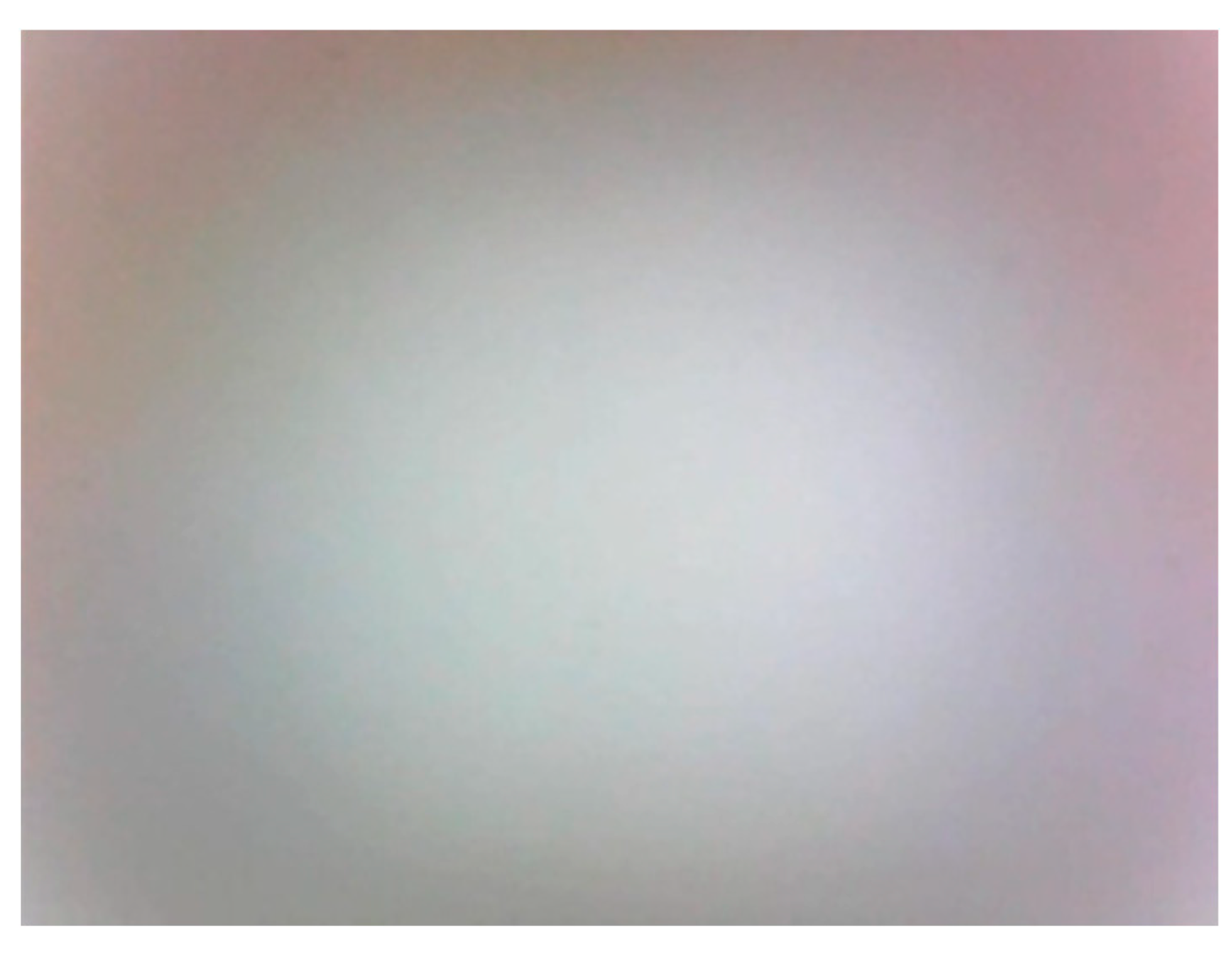
Relative movements between particles, lubricant and camera are the main causes of motion blur in the dynamic wear debris image. But the background of the particle image is usually regarded as static because its appearance is only affected by the lubricant. The property of the lubricant remains stable in a short duration when the machine is running, and this makes the background look similar. Thus, the dynamic particle image is categorized as a partial motion-blurred image. Despite researches on image restoration have been widely reported, most of them had focused on the whole image and partial blur issue was seldom explored.
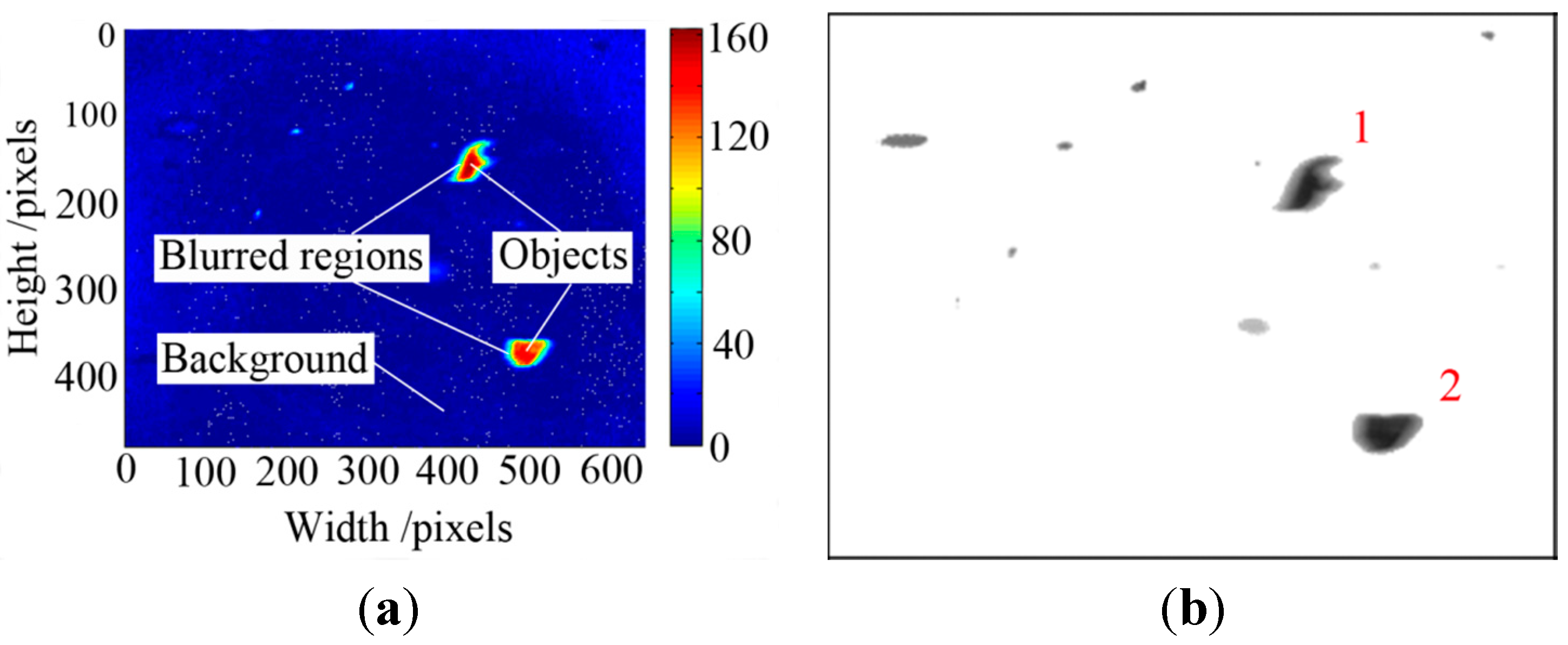
In order to deal with the partial blur problem, three issues need to be addressed. They are partial blur detection, blur angle and length estimation, and partial deblurring. The blur regions identification is of profound importance in local blurred image processing, and there are two successful approaches reported. Chen [
13] proposed an approach of directional high-frequency energy analysis to detect motion blurred regions. This method assumes that objects are in motion with a constant velocity. However, wear particle flowing in the lubricant are moving at various velocities, making it difficult to apply the directional high-frequency energy analysis approach to perform partial blur detection. The other blur detection approach is based on morphology for objects segmentation to separate blur regions [
14]. Moving particles are the objects in an on-line wear debris image. But the morphology method is not sufficient for wear particle segmentation because of the influence from uneven lighting and reduction of contrast due to oil opaqueness [
15]. The gradient-based object segmentation hence cannot be directly applied to effectively extract blurred particles because the gray values of the particles are close to that of the background.
With regard to blur estimation, as the degraded image is the result of the convolution between a sharp image and a point spread function (PSF), the Fourier transform based technique is one of the practical measures to restore blurred images. It is because the PSF parameters can be found from the given blurred image by further converting the image to the spectrum and cepstrum domain [
16,
17]. In image deblurring, many image restoration algorithms have been reported, such as Lucy-Richardson [
18], least squares [
19], blind deconvolution [
20] and Wiener filter [
2]. In the existing approaches, Wiener filter is a method with good restoration effectiveness and calculation simplicity [
21]. It is also an attractive candidate for blur estimation and restoration of dynamic wear debris images in real-time wear condition monitoring.
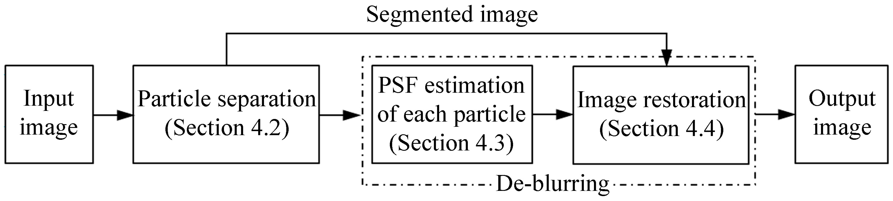
In this work, a method is developed to restore motion-blurred wear debris images. The aim is to improve the quality of the blurred particles and segment the particles for on-line wear monitoring. This approach involves three phases. In the first stage, the static background image is sampled using the video-based debris imaging system. Particles are separated from the background based on background subtraction method [
22]. In this step, the partial blur regions are detected. Second, PSF parameters including the blur direction and blur length of each blurred particle are estimated using power cepstrum. Finally, the Wiener filter algorithm is adopted to restore the segmented image based on the average PSF values to output an improved quality image.
The rest of the paper is organized as follows. In
Section 2, the wear debris imaging system in on-line monitoring is introduced, as well as the characteristics of dynamic particle image. The traditional image restoration process using Wiener filter is described in
Section 3. The developed approach of particle image processing is presented in
Section 4.
Section 5 reports experiments carried out to verify the performance of the presented method. The effective factors on the results are also discussed. Finally, conclusions are drawn in
Section 6.
3. Related Works on Image Restoration
A blurred image in
xy-coordinates can be expressed with a degradation model depicted in
Figure 3. As shown in the figure, a motion-blurred image
g(
x,
y) is represented in the form of convolution operation between the sharp image
f(
x,
y) and a degradation function
h(
x,
y), and the resultant image is usually affected by additive noise
n(
x,
y).
Figure 3.
Image degradation model of motion blur [
15].
Figure 3.
Image degradation model of motion blur [
15].
The mathematical relationship between the final blurred image
g(
x,
y), the sharp image
f(
x,
y), degradation function
h(
x,
y) and random noise
n(
x,
y) is expressed as
where “*” denotes the convolution operator.
The blurring operation can be converted to the Fourier transform domain as
where
G(
u,
v),
F(
u,
v),
H(
u,
v) and
N(
u,
v) are the results of Fourier transformation of
g(
x,
y),
f(
x,
y),
h(
x,
y) and
n(
x,
y), respectively.
In order to obtain the sharp image
f(
x,
y) by reversing the degradation process, the Wiener filter algorithm [
23] is used to restore the particle images. The aim of image restoration is to acquire an estimated image
of the original and sharp image
f(
x,
y) with a least mean square error between the two images. The mathematical expression of the Wiener filter is [
23]
where,
is the Fourier transform of
; γ is the noise-to-signal power ratio of the additive noise.
The degradation function
h(
x,
y) is commonly known as the point spread function. In a motion-blurred image, the PSF is affected by two factors, that are, blur length
L and blur angle θ, which are calculated by [
24]
where,
x and
y are the horizontal and vertical movement directions by some distance, respectively.
Consequently, the estimated parameters,
L and θ, are the basis for image restoration. As Equation (2) shows, the degraded image of the convolution result can be transformed to Fourier spectrum domain. Therefore, the blur information contained in the PSF parameters can be extracted by inverse Fourier transform, which is the power cepstrum. The cepstrum
Cg(
p,
q) of an image is defined as
where
FFT−1{·} is the inverse Fourier transformation. As can be seen, the power cepstrum is the inverse Fourier transform of the logarithm of the squared magnitude of the Fourier transform of the degraded image. Fourier spectral null is unavoidable in an image, and the logarithm of zero is negative infinite. In order to ensure the effectiveness of Equation (5), the cepstrum of an image is generally calculated using [
25]
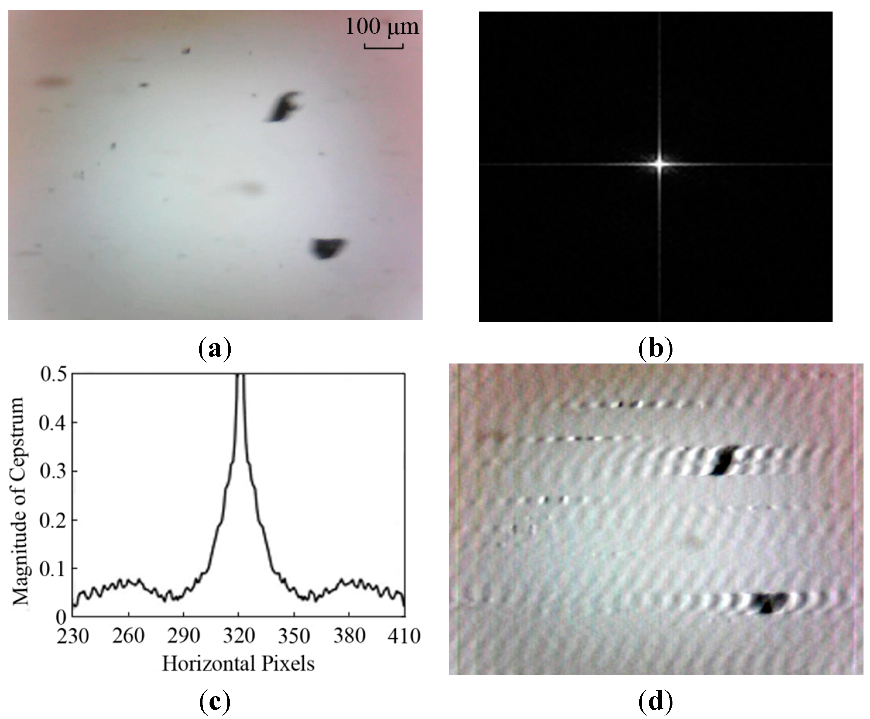
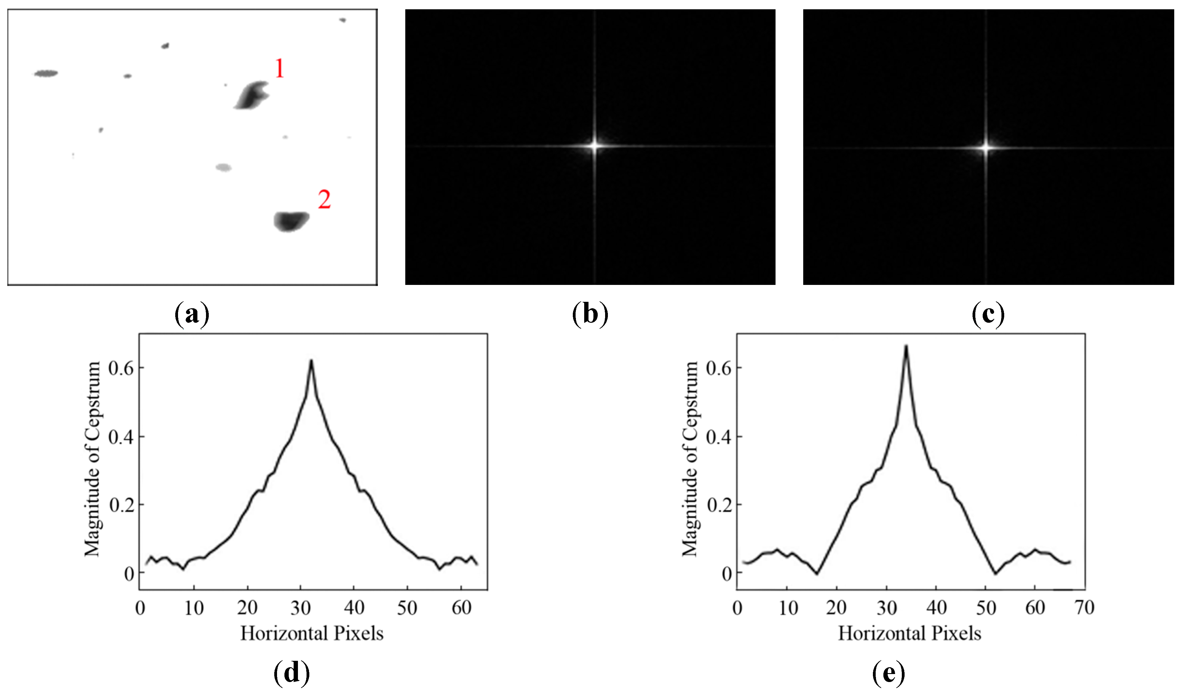
By transforming the degraded image (see
Figure 4a) to the cepstrum domain as shown in
Figure 4b,c, the PSF parameters,
L and θ, are determined. Generally, the direction of motion blur is estimated by measuring the angle between any one of the parallel stripes and the horizontal axis in the cepstrum chart. From
Figure 4b, parallel stripes can hardly be found. The blur angle is estimated as θ = 0° where the direction of particle motion is aligned to 0° by adjusting the camera position. In addition, there are two symmetric lowest peaks in a cepstrum magnitude curve. The distance between two peaks is equal to twice the blur length. However, the cepstrum in
Figure 4c is affected by the oil contaminants in the background. The blur length in the example shown in
Figure 4a is approximately determined as
L = 41 pixels.
When the PSF parameters are estimated, the motion-blurred image can be restored based on Wiener filter method and the output image is shown in
Figure 4d. It is observed that the particles become sharper but there are artifacts appearing in the background. This result caused by over-restoration of an entire image is unsatisfactory to extract accurate wear particle information.
Figure 4.
Restored results based on the whole image: (a) dynamic wear debris image; (b) power cepstrum; (c) cepstrum Magnitude; and (d) output image.
Figure 4.
Restored results based on the whole image: (a) dynamic wear debris image; (b) power cepstrum; (c) cepstrum Magnitude; and (d) output image.
5. Experimental Results and Discussion
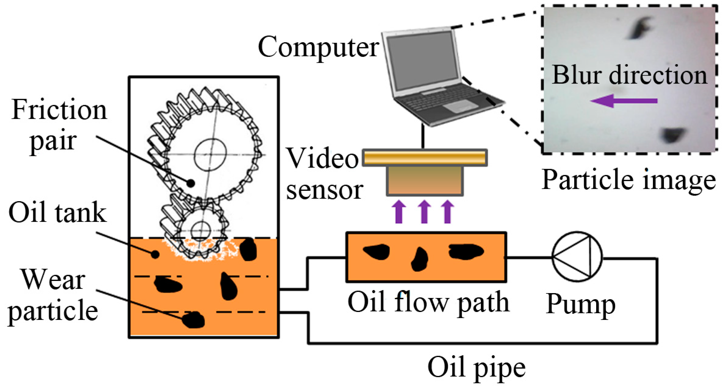
To evaluate the performance of the proposed motion-blurred image restoration method, dynamic wear debris images were captured from on-line monitoring lubrication samples of a mine scraper conveyor gearbox. The video-based imaging system in
Figure 1 was used to capture particle images. All the images are of 640 × 480 pixels in the JPEG format. Aiming for performance evaluations, two tests were carried out with a total of 110 images. The first test includes images restored using the existing approach on the whole image (see
Section 3) and the proposed approach (
Section 4), respectively. The second test is to compare the Wiener filter (WF) with other three common image restoration methods that are Lucy-Richardson (LR) [
18], blind deconvolution (BD) [
20] and least squares (LS) [
19].
5.1. Comparative Test One
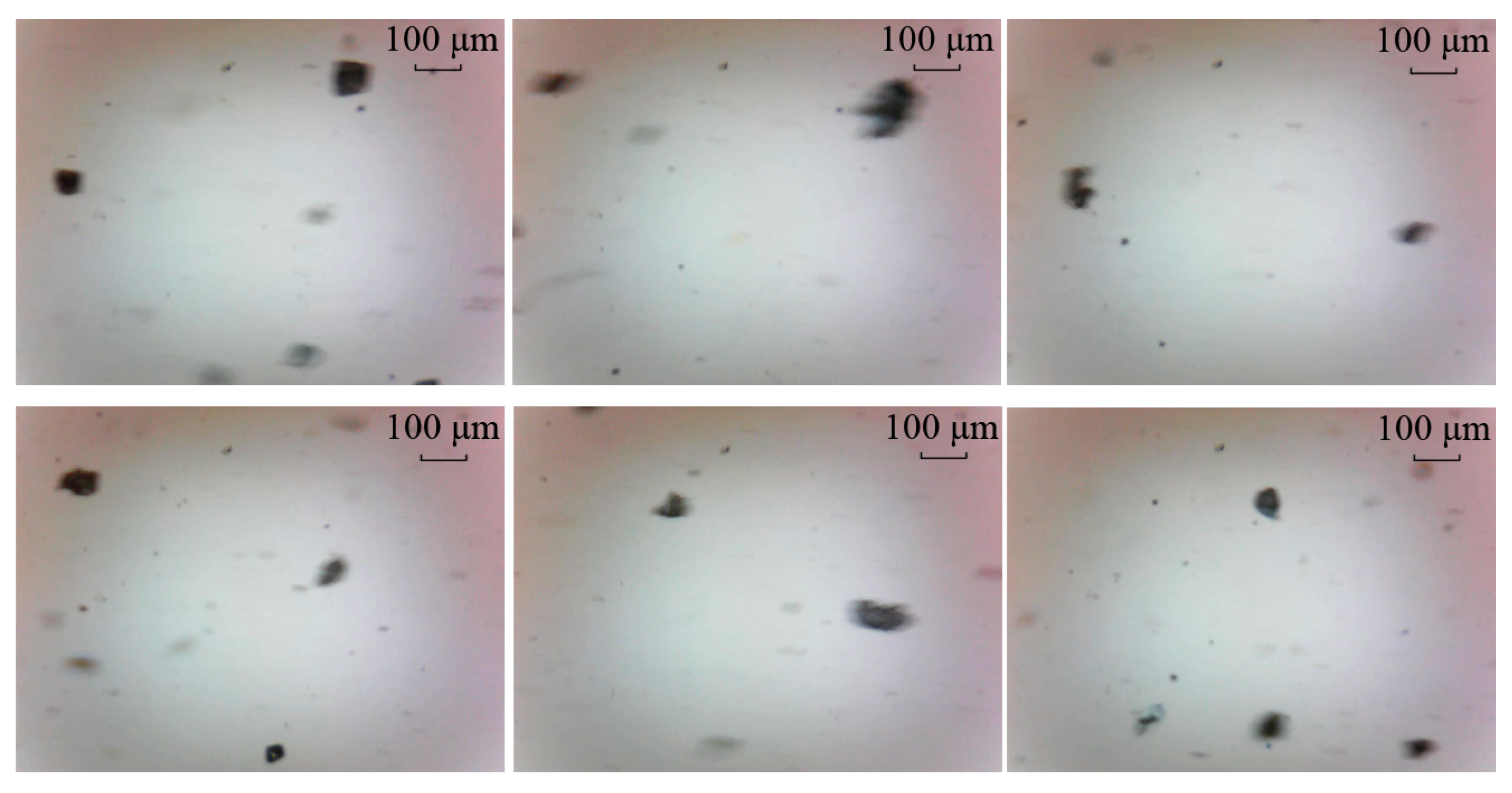
To examine the potential advantages of the proposed method, dynamic wear debris images were obtained to access the performance of the proposed local blurred particle restoration approach. Six tested images as the input are depicted in
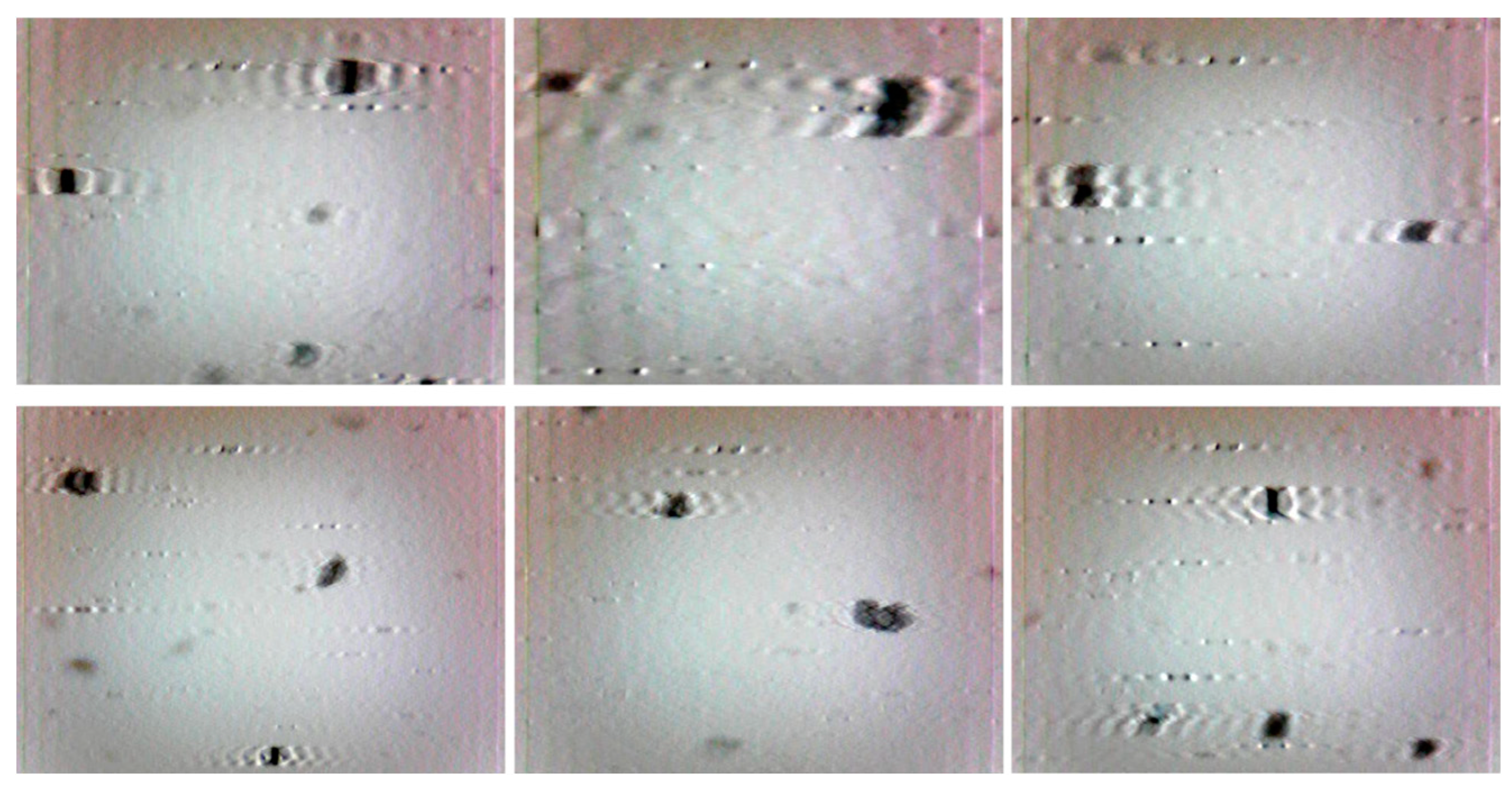
Figure 10. The processed results, using the existing image restoration method based on the whole image, are shown in
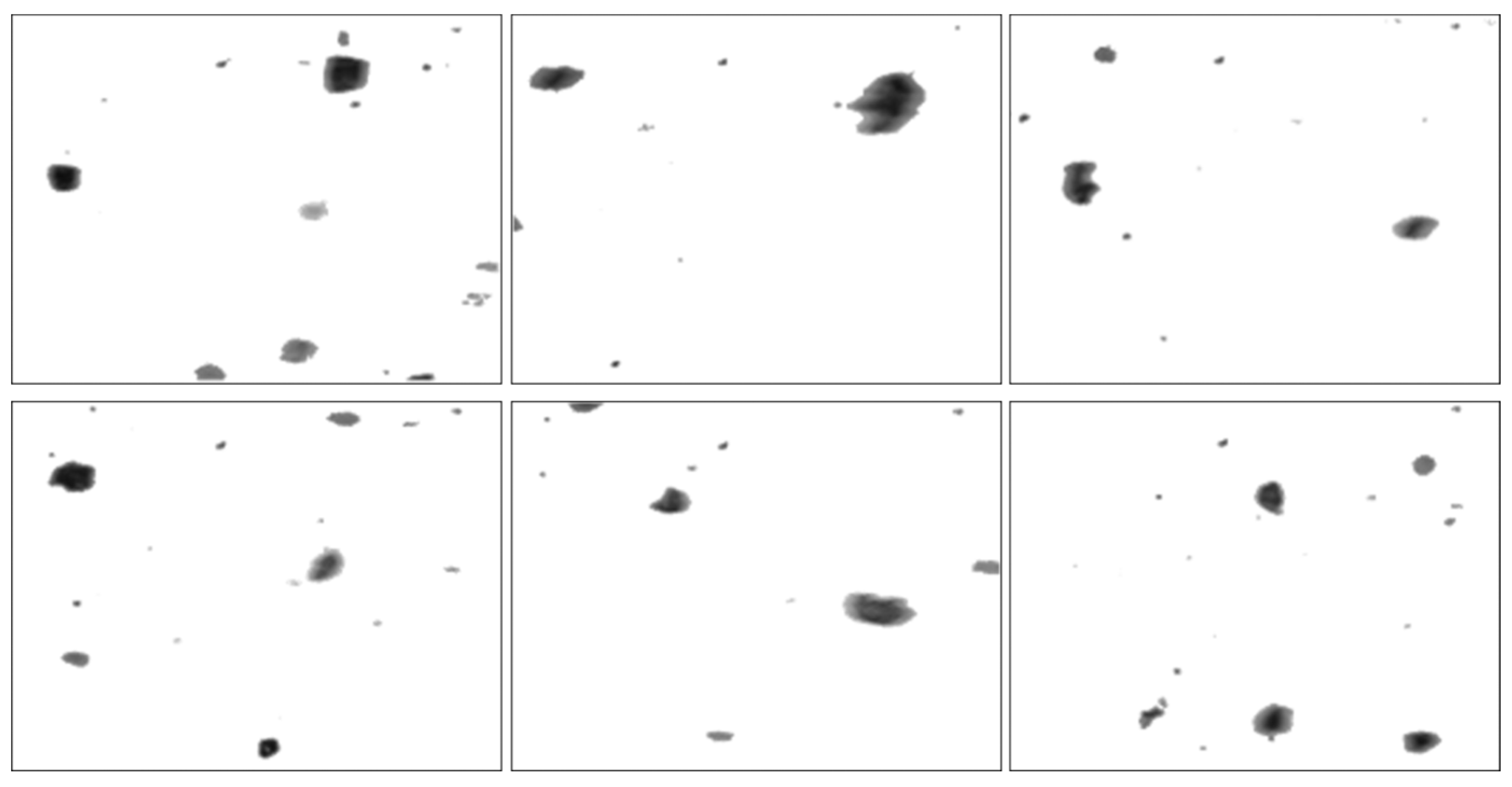
Figure 11. The segmented particle images and the restored results, using the newly developed approach, are displayed in
Figure 12 and
Figure 13, respectively.
Figure 10.
Six input particle images.
Figure 10.
Six input particle images.
Figure 11.
Restored results based on the whole image.
Figure 11.
Restored results based on the whole image.
Figure 12.
Segmented particle images using the approach presented in
Section 4.
Figure 12.
Segmented particle images using the approach presented in
Section 4.
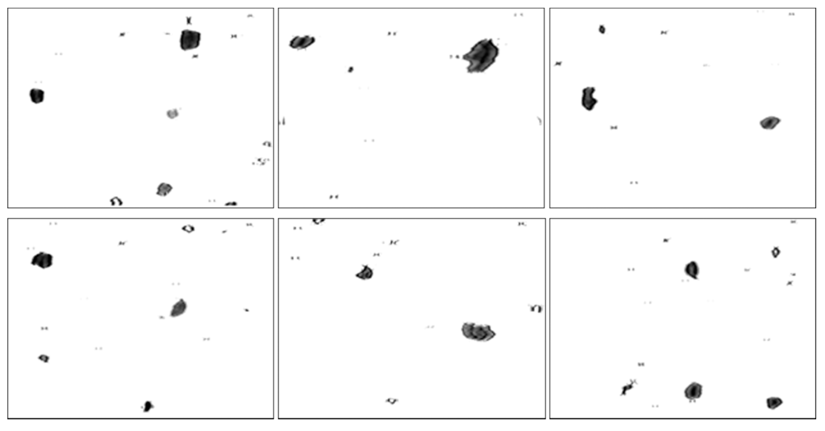
Figure 13.
Restored images using the proposed method.
Figure 13.
Restored images using the proposed method.
It can be seen from
Figure 11 that most of the particles were over-restored because the estimated blur length based on the whole image was larger than that of the blurred debris. At the same time, undesirable artifacts introduced in the background make these images not desirable to do image pre-processing for debris features extraction.
In contrast,
Figure 12 demonstrates that the similar background in
Figure 10 was removed by utilizing the particle separation method. But the information of particles cannot be extracted directly from the segmented images because the blur regions due to the movements of particles are retained, which will affect the accuracy of wear debris feature extraction.
As shown in
Figure 13, the sharpness of the particles was improved. The restored particles based on the proposed method of object separation are sharper than that based on the whole image, which is more suitable for WDA in a subjective visual assessment. In addition, the grey contrast between particles and background was also increased comparing to that in
Figure 12, making it easy to extract the information of particles.
For further analysis, the proposed method was also assessed quantitatively. The purpose of motion-blurred wear debris image restoration is to improve the contrast between particles and background to extract debris features. Pixel gradient,
G, is a sharpness measure to evaluate the object edges. It is calculated from the neighborhood pixel gradient
as
and
where,
U and
V are the width and height of the image, respectively;
N is the total number of pixels in the image and
N =
U ×
V;
,
are the gradients in the horizontal and vertical directions in the image;
g is the grey value of a pixel.
All 110 images were restored using the proposed method based on the segmented images. The gradients of the original segmented images and the restored images were calculated and are displayed in
Figure 14. The results show that all the gradients of the restored images in a range of [0.522, 2.288] are larger than that of the blurred images ([0.173, 0.517]). This clearly demonstrates that the restored images have much sharper edges than the original ones, proving that the proposed method of particle restoration is effective for dynamic wear debris analysis in on-line wear monitoring.
Figure 14.
Gradients of the segmented and restored images.
Figure 14.
Gradients of the segmented and restored images.
5.2. Comparative Test Two
The Wiener filter is utilized to remove the motion blur in the restoration procedure to improve the quality of images. To demonstrate the Wiener filter is more suitable for dynamic wear debris image processing, the results are compared against other three common algorithms, including Lucy-Richardson (LR), blind deconvolution (BD) and least squares (LS). Two sample images as the input images are depicted in
Figure 15a and
Figure 16a. The restored results using the four methods based on the whole image and the partial blurred particle regions are presented in
Figure 15b–i and
Figure 16b–i, respectively.
From
Figure 15b–e and
Figure 16b–e, it can be seen that over-restoration of the background based on the entire image makes these images not desirable to pursue image pre-processing. As shown in
Figure 15f–i and
Figure 16f–i, the restored results of separated wear particles are appropriate for wear debris analysis in a subjective visual assessment. The above comparisons, in addition to the comparisons made in
Section 5.1, further confirm that the developed local blurred particle restoration approach works well in improving the image quality.
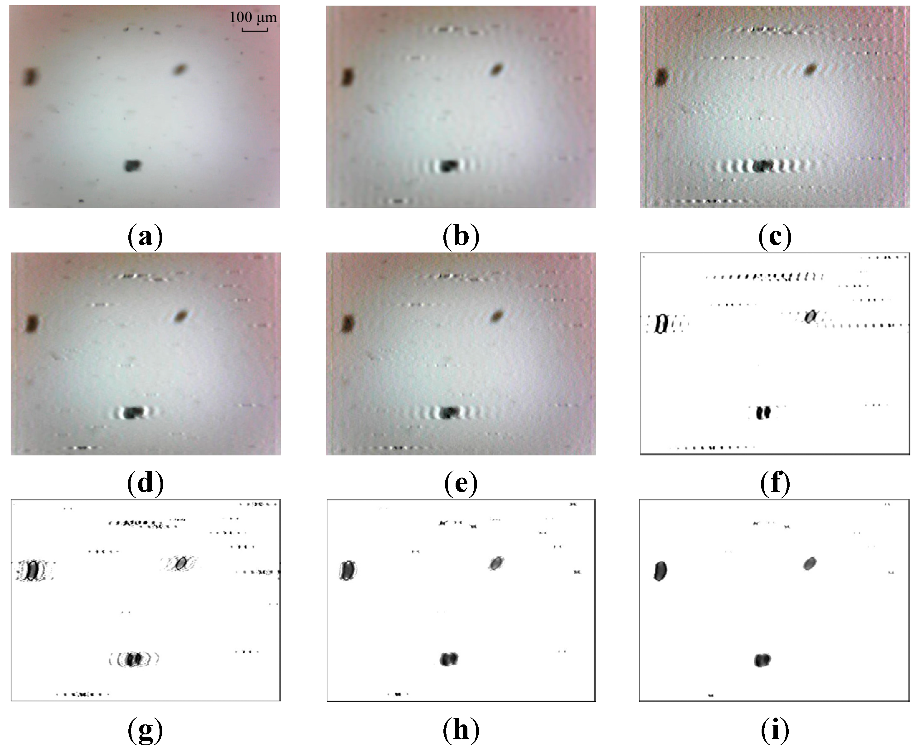
Figure 15.
Test results—image 1: (a) input image; (b–e) restored images by LS, BD, LR and WF based on the whole image, respectively; and (f–i) output images by LS, BD, LR and WF based on local blurred regions, respectively.
Figure 15.
Test results—image 1: (a) input image; (b–e) restored images by LS, BD, LR and WF based on the whole image, respectively; and (f–i) output images by LS, BD, LR and WF based on local blurred regions, respectively.
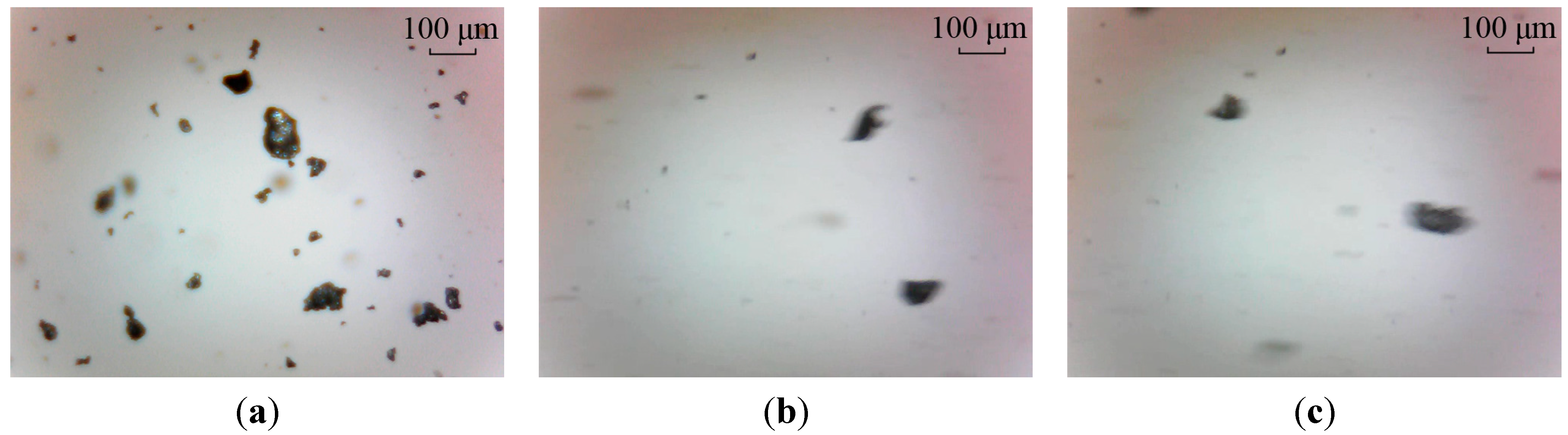
Figure 16.
Test results—image 2: (a) input image; (b–e) restored images by LS, BD, LR and WF based on the whole image, respectively; and (f–i) output images by LS, BD, LR and WF based on local blurred regions, respectively.
Figure 16.
Test results—image 2: (a) input image; (b–e) restored images by LS, BD, LR and WF based on the whole image, respectively; and (f–i) output images by LS, BD, LR and WF based on local blurred regions, respectively.
In
Figure 15f the target particles are well restored with LS. But the result is unstable. Unwanted artifacts are sometimes introduced in the output image (see
Figure 16f), which will affect the accuracy of particle extraction. This phenomenon of artifacts appearance can also be seen in the processed results by BD, as shown in
Figure 15g and
Figure 16g.
The LR and WF methods are better at restoring motion-blurred particle images, comparing with the methods of LS and BD, as shown in
Figure 15h,i and
Figure 16h,i. It is observed that the processed results are similar using the methods of LR and WF. Further comparison is described in the following.
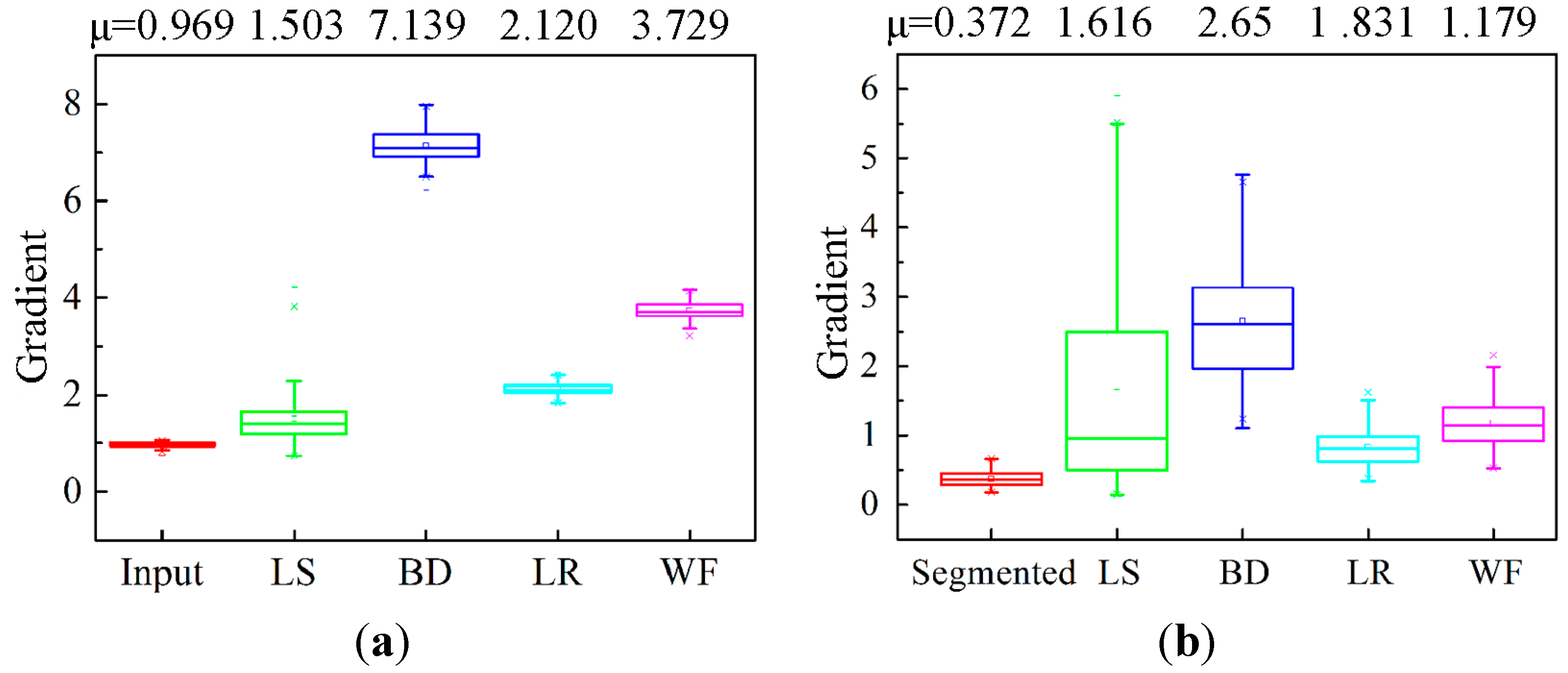
Figure 17 shows the boxplots of all 110 experimental images gradient measures using the four common image restoration methods. In
Figure 17a, the mean gradients based on the whole image are much larger than that of the input image (0.969). This is because over-restoration makes the background not smooth after image processing as mentioned above.
Figure 17.
Boxplots of all 110 experimental image gradients: (a) gradient of the processed image based on the whole image and (b) gradient of the restored result based on partial blurred region.
Figure 17.
Boxplots of all 110 experimental image gradients: (a) gradient of the processed image based on the whole image and (b) gradient of the restored result based on partial blurred region.
The mean gradients in
Figure 17b show that all the gradients of the restored images by the four methods are larger than that of the blurred images. But the wide statistical gradient distribution range [0.150, 5.496] and the higher interquartile range of LS indicate that the LS method is undesirable for dynamic particle image processing. In the BD method, its mean value of 2.651 is the highest due to unnecessary artifacts appearing in the image as mentioned above, which will affect the particle features extraction. The output results of the LR and WF are better than the other two methods. The higher value of 1.179 of the Wiener filter than 0.831 of the Lucy-Richardson indicates that WF algorithm is superior to dealing with the motion-blurred problem by improving the grey contrast between particles and background.
5.3. Further Discussion
The above comparative analyses confirm that the proposed method of particle restoration is effective in dealing with the motion blur problem in the dynamic particle imaging system. By detecting and segmenting the partial blurred particle regions, a localized approach is, for the first time, introduced for blur removal by applying deblurring operations to individual wear particles.
Furthermore, the developed approach can be applied or further developed for other applications where dynamic images need to be captured and analyzed. For example, vehicle monitoring is important in the field of intelligent transportation. The relative movements of moving cars to static cameras cause the images blurring, making it difficult for target recognition [
30]. Despite the influence of external environment, the background model of current car image can be established by real-time background updating. Hence, the proposed method can be applied to restore the partial blurred car regions to obtain high quality images. Another potential application is to use the developed method to obtain clear star maps so aircraft attitudes can be estimated [
2]. It is possible to develop the object separation method to segment the blurred region for target restoration using the Wiener filter algorithm to improve the quality of the star image. In short, the approach presented in this paper is not limited to improving dynamic image quality for on-line wear debris analysis; it can be developed and applied for other applications where dynamic images are captured.
More work needs to be done to further improve the developed method. First, unstable illumination affects the segmentation threshold accuracy and consequently on the background extracted. This issue is not taken into consideration in this work because a pre-calibration is carried out before acquiring the images. In future work, we will investigate automatic illumination corrections to improve the accuracy and efficiency of the particle separation. Second, it is necessary to reduce the impacts of external noises. Effected by noises, holes within particles and artifacts may be produced in the segmented image. At present, uncorrelated noise in the background image are reduced by real-time background updating. The noise in the particle images will be eliminated by utilizing median filtering and binary morphological operations [
31] in the further research of extracting particle characteristics for wear mechanism examinations.


