
An Intelligent Optical Dissolved Oxygen Measurement Method Based on a Fluorescent Quenching Mechanism


Abstract
:
1. Introduction
2. Materials and Methods
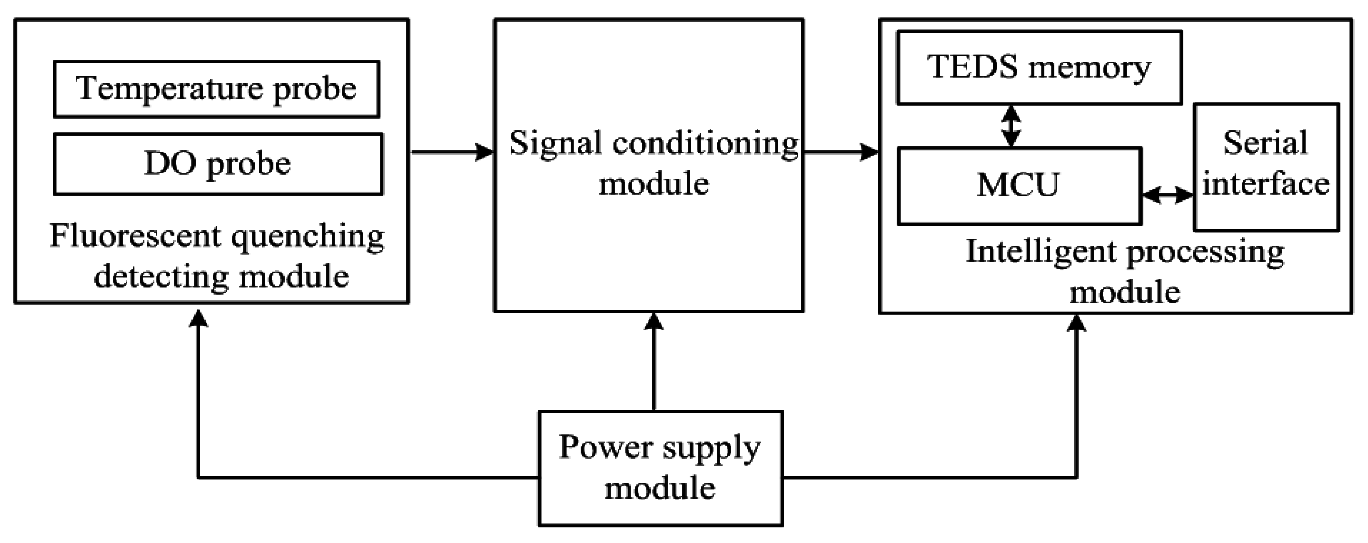
2.1. The Overall Design of Optical Dissolved Oxygen Sensor
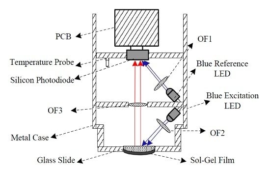
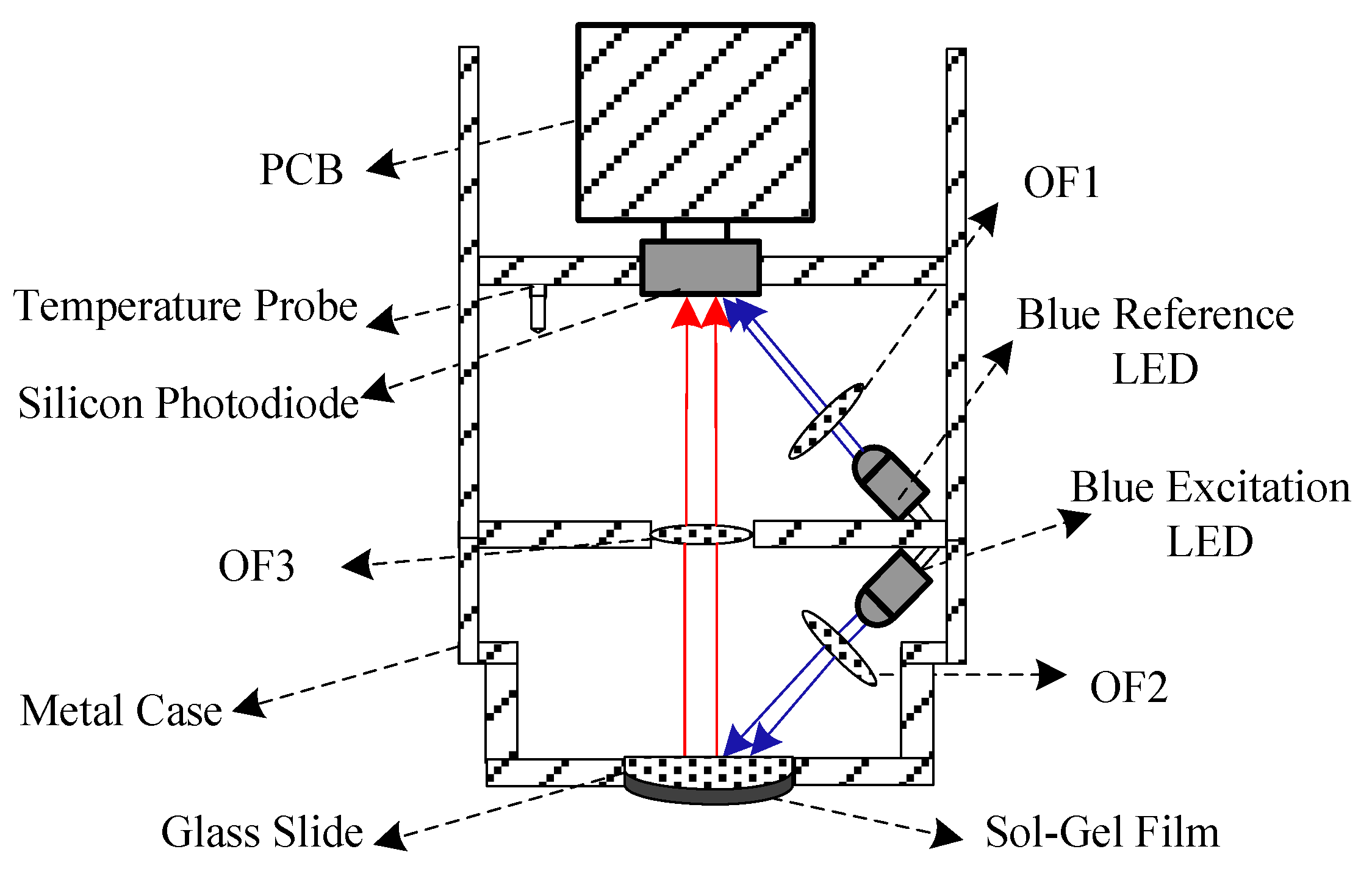
2.2. Design of the Fluorescent Quenching Detection Module
- F0 denotes the fluorescence signal intensity of anaerobic water;
- F denotes the fluorescence signal intensity of the water samples;
- KSV denotes the Stern-Volmer constant; and
- [Q] denotes the concentration of quencher.
2.3. Design of the Signal Conditioning Module
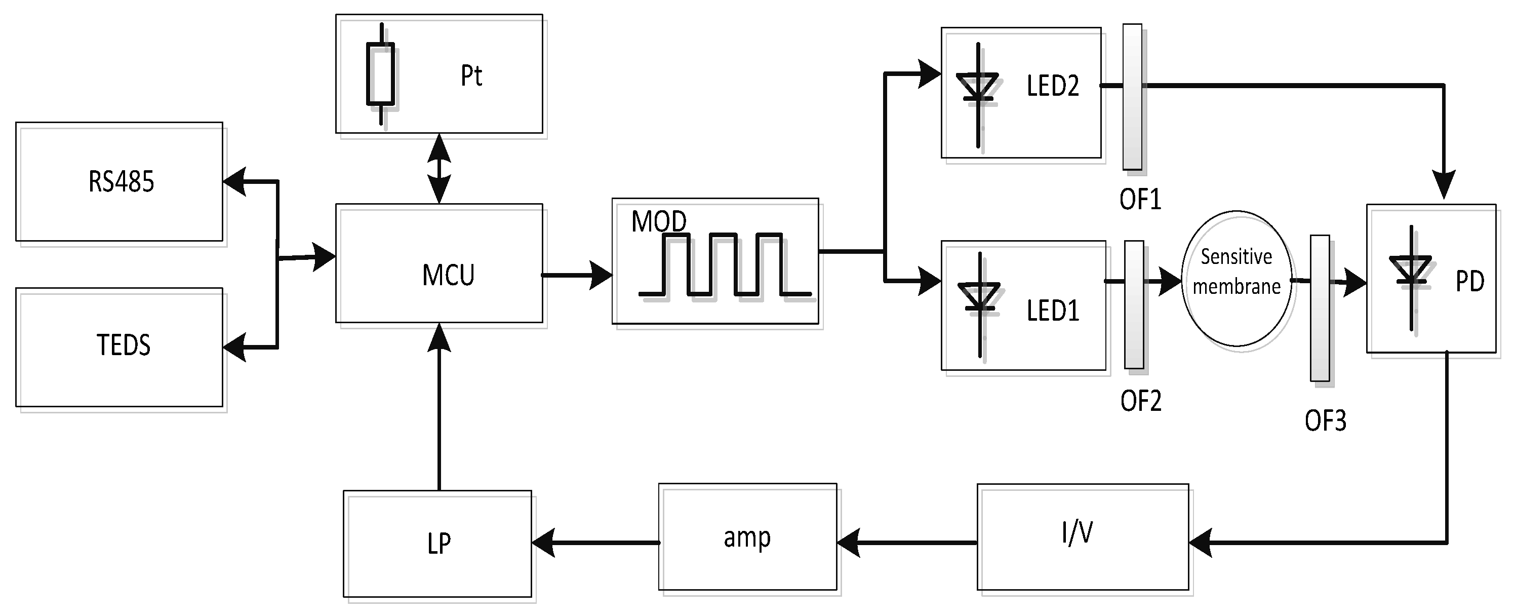
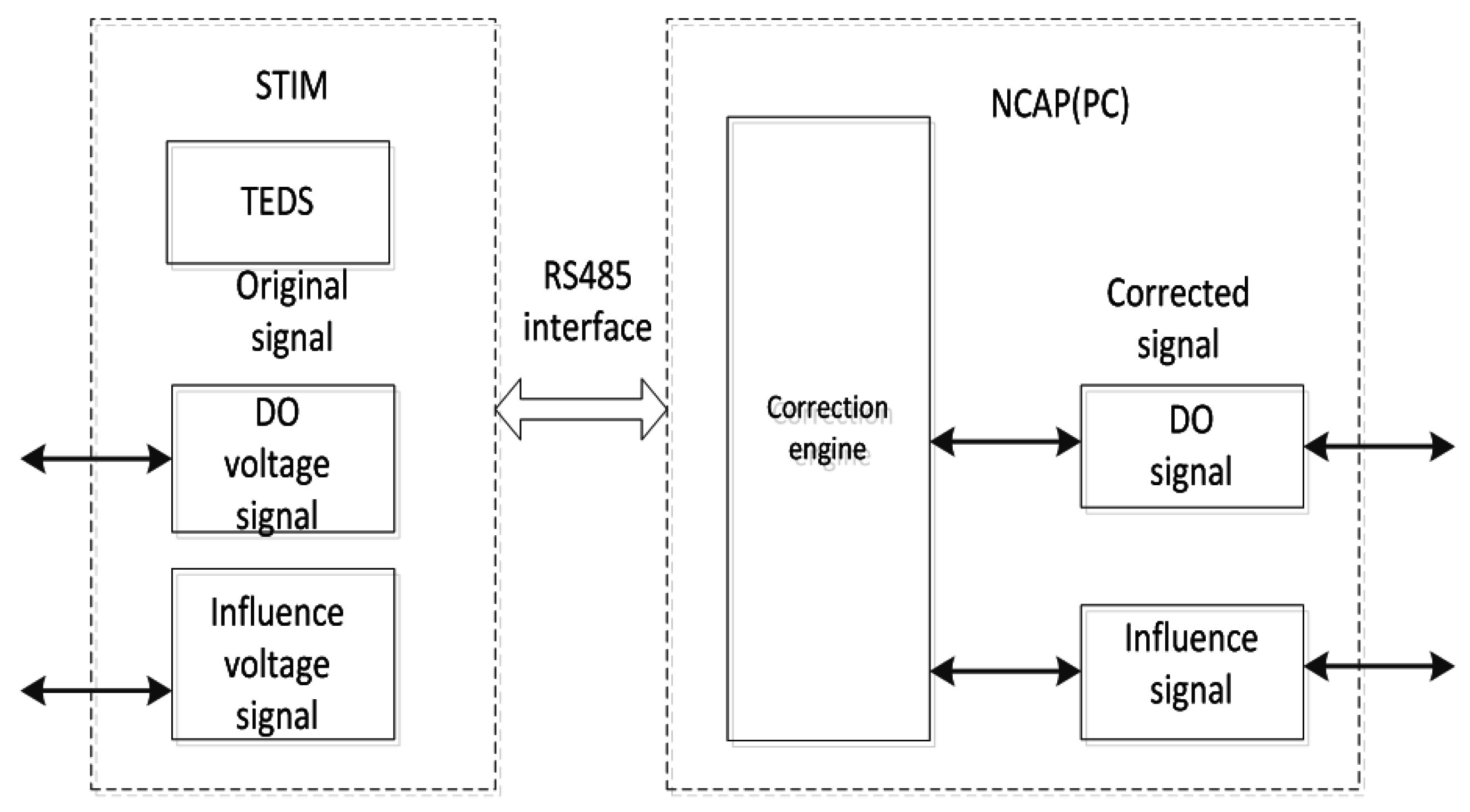
2.4. Design of the Intelligent Processing Module
IEEE1451.2 Standard
3. Experiments and Discussions
3.1. Calibration and Validation
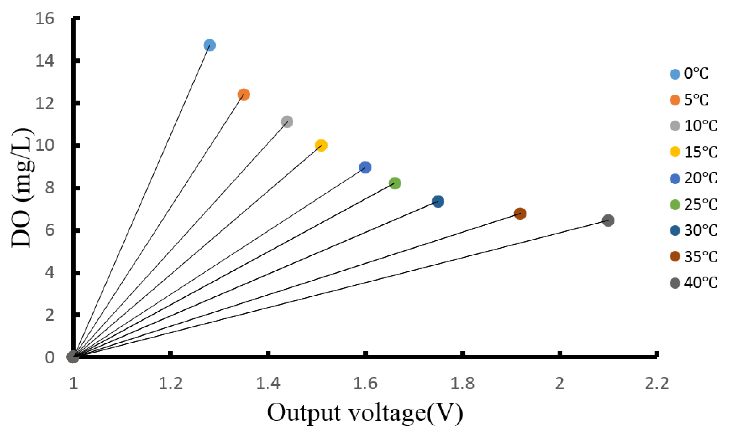
3.1.1. Temperature Compensation of the Optical DO Sensor

3.1.2. Pressure Compensation of the Optical DO Sensor

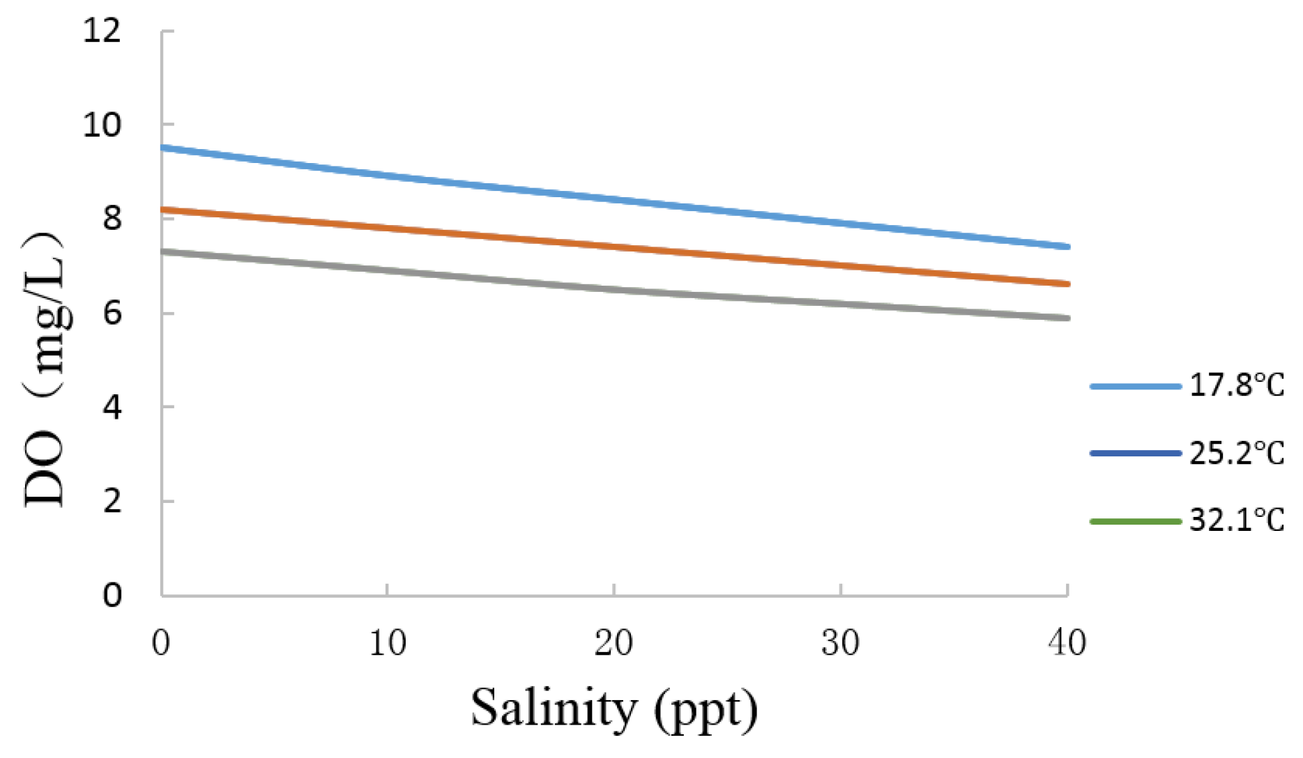
3.1.3. Salinity Compensation of the Optical DO Sensor
3.1.4. Excitation LED Compensation
3.2. Analysis of the Performance of the Sensor
3.2.1. Accuracy Test

| Samples | Measurements | AVG | Absolute Error | Relative Error | |||||||
|---|---|---|---|---|---|---|---|---|---|---|---|
| 1 | 2 | 3 | 4 | 5 | 6 | 7 | 8 | ||||
| 5.02 | 4.86 | 4.79 | 4.89 | 4.93 | 4.89 | 4.91 | 5.09 | 4.98 | 4.92 | 0.1 | 1.99% |
| 9.98 | 10.12 | 10.09 | 10.21 | 9.89 | 10.06 | 9.91 | 9.89 | 10.13 | 10.04 | 0.06 | 0.60% |
| 18.03 | 17.85 | 17.83 | 17.91 | 17.87 | 17.96 | 17.87 | 17.93 | 18.03 | 17.91 | 0.12 | 0.67% |
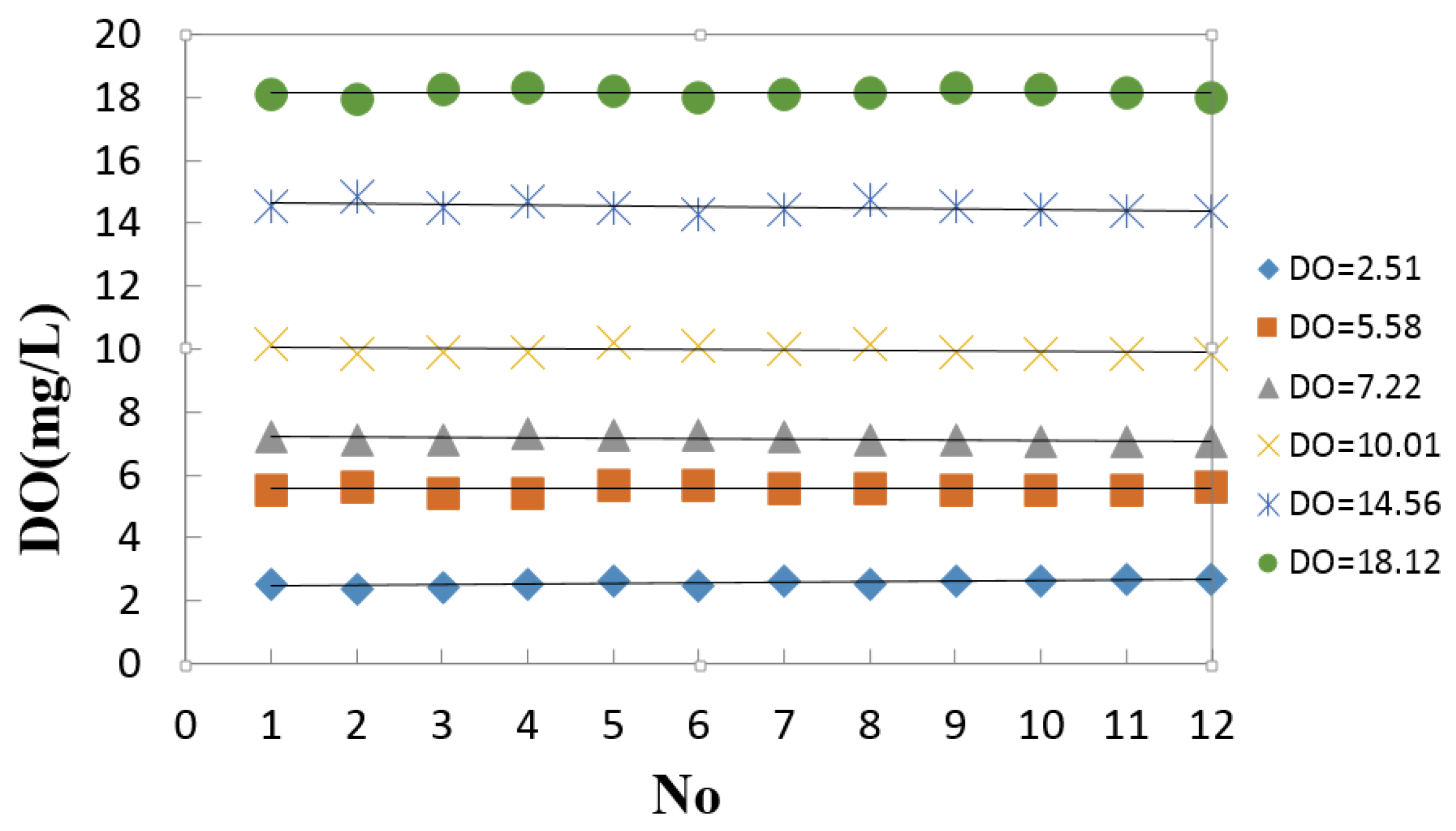
3.2.2. Stability Test
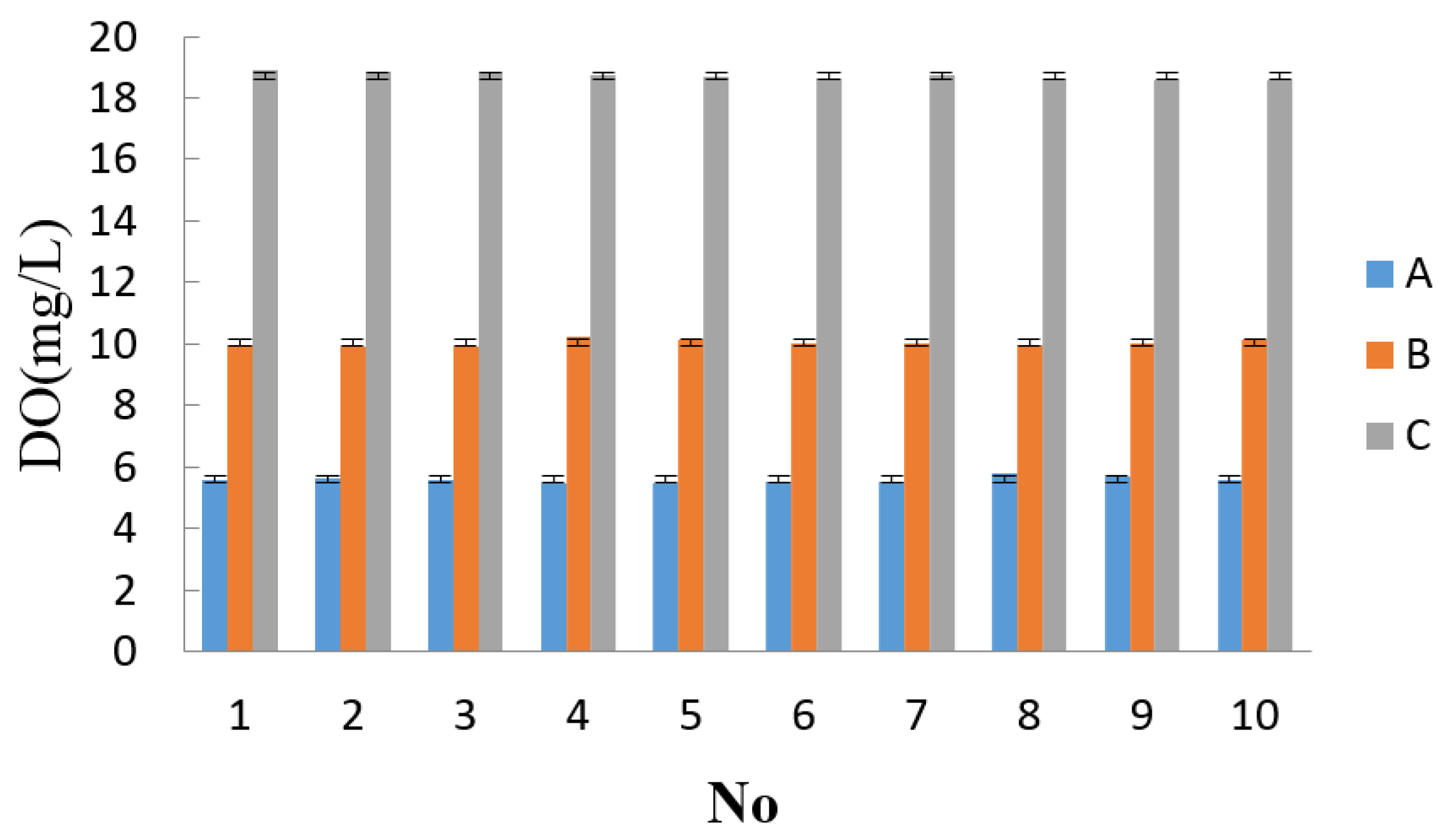
3.2.3. Precision Test
| Sample | 1 | 2 | 3 | 4 | 5 | 6 | 7 | 8 | 9 | 10 | AVG Average average | RSD |
|---|---|---|---|---|---|---|---|---|---|---|---|---|
| A | 5.56 | 5.62 | 5.60 | 5.44 | 5.49 | 5.51 | 5.50 | 5.82 | 5.71 | 5.60 | 5.59 | 1.97% |
| B | 9.96 | 9.91 | 9.89 | 10.22 | 10.15 | 10.04 | 10.00 | 9.98 | 10.02 | 10.15 | 10.03 | 1.10% |
| C | 18.90 | 18.85 | 18.86 | 18.74 | 18.69 | 18.56 | 18.74 | 18.63 | 18.60 | 18.59 | 18.73 | 0.64% |
3.2.4. Repeatability Test
| Samples | Measurement Results | Relative Error | |||||||||
|---|---|---|---|---|---|---|---|---|---|---|---|
| 1 | 2 | 3 | 4 | 5 | 6 | 7 | 8 | 9 | 10 | ||
| 2.51 | 2.54 | 2.5 | 2.44 | 2.56 | 2.62 | 2.48 | 2.63 | 2.55 | 2.59 | 2.63 | 1.59% |
| 9.24 | 9.22 | 9.19 | 9.16 | 9.13 | 9.33 | 9.25 | 9.23 | 9.22 | 9.16 | 9.13 | 0.43% |
| 12.51 | 12.49 | 12.44 | 12.45 | 12.44 | 12.67 | 12.71 | 12.58 | 12.55 | 12.49 | 12.51 | 0.16% |
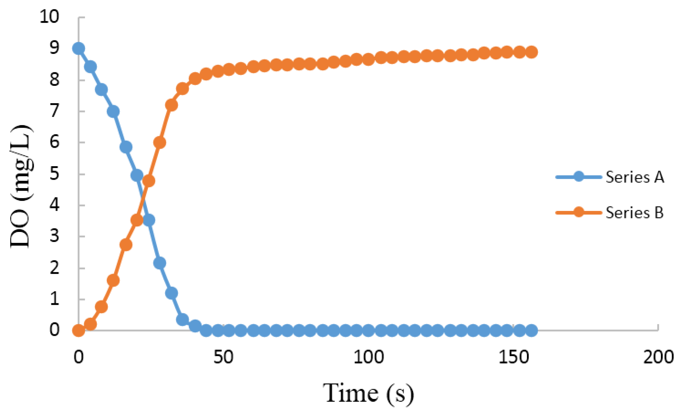
3.2.5. Speed Test
3.2.6. On-Site Verification Test

4. Conclusions
Acknowledgments
Author Contributions
Conflicts of Interest
References
- Gao, M.; Zhang, F.; Tian, J. Dissolved oxygen online acquisition terminal based on wireless sensor network. In Proceedings of the 2008 4th International Conference on Wireless Communications, Networking and Mobile Computing (WiCOM), Dalian, China, 12–14 October 2008; pp. 1–4.
- Niu, C.; Zhang, Y.; Zhou, Y.; Shi, K.; Liu, X.; Qin, B. The Potential Applications of Real-Time Monitoring of Water Quality in a Large Shallow Lake (Lake Taihu, China) Using a Chromophoric Dissolved Organic Matter Fluorescence Sensor. Sensors 2014, 14, 11580–11594. [Google Scholar] [CrossRef] [PubMed]
- Chong, S.; Aziz, A.; Harun, S. Fibre Optic Sensors for Selected Wastewater Characteristics. Sensors 2013, 13, 8640–8668. [Google Scholar] [CrossRef] [PubMed]
- Wilhelm Filho, D.; Torres, M.A.; Zaniboni-Filho, E.; Pedrosa, R.C. Effect of different oxygen tensions on weight gain, feed conversion, and antioxidant status in piapara, Leporinus elongatus (Valenciennes, 1847). Aquaculture 2005, 244, 349–357. [Google Scholar] [CrossRef]
- Foss, A.; Vollen, T.; Øiestad, V. Growth and oxygen consumption in normal and O2 supersaturated water, and interactive effects of O2 saturation and ammonia on growth in spotted wolffish (Anarhichas minor Olafsen). Aquaculture 2003, 224, 105–116. [Google Scholar] [CrossRef]
- Wang, J.; Bian, C.; Tong, J.; Sun, J.; Li, Y.; Hong, W.; Xia, S. Modification of Graphene on Ultramicroelectrode Array and Its Application in Detection of Dissolved Oxygen. Sensors 2015, 15, 382–393. [Google Scholar] [CrossRef] [PubMed]
- Ramamoorthy, R.; Dutta, P.K.; Akbar, S.A. Oxygen sensors: Materials, methods, designs and applications. J. Mater. Sci. 2003, 38, 4271–4282. [Google Scholar] [CrossRef]
- Dai, W.Y.; Sun, L. The Measurement Methods of Dissolved Oxygen in Water. Anhui Agri. Sci. Bull. 2007, 13, 77–79. [Google Scholar]
- Novic, M.; Pihlar, B.; Dular, M. Use of flow injection analysis based on iodometry for automation of dissolved oxygen (Winkler method) and chemical oxygen demand (dichromate method) determinations. Fresenius Z. Anal. Chem. 1988, 332, 750–755. [Google Scholar] [CrossRef]
- Zhao, Y.; Sun, L.; Li, F.M. The research about detection of dissolved oxygen in water based on C8051F040. In Proceedings of the 2009 International Conference on Information Engineering and Computer Science, ICIECS 2009, Wuhan, China, 19–20 December 2009; pp. 1–4.
- Landman, M.J.; van den Heuvel, M.R. An improved system for the control of dissolved oxygen in freshwater aquaria. Water Res. 2003, 37, 4337–4342. [Google Scholar] [CrossRef]
- Jalukse, L.; Leito, I.; Mashirin, A.; Tenno, T. Estimation of uncertainty in electrochemical amperometric measurement of dissolved oxygen concentration. Accred. Qual. Assur. 2004, 9, 340–348. [Google Scholar] [CrossRef]
- Hasumoto, H.; Imazu, T.; Miura, T.; Kogure, K. Use of an optical oxygen sensor to measure dissolved oxygen in seawater. J. Oceanogr. 2006, 62, 99–103. [Google Scholar] [CrossRef]
- Helm, I.; Jalukse, L.; Vilbaste, M.; Leito, I. Micro-Winkler titration method for dissolved oxygen concentration measurement. Anal. Chim Acta 2009, 648, 167–173. [Google Scholar] [CrossRef] [PubMed]
- Li, A.; Wang, Y.; Hu, Q.; Shieh, W. Few-mode fiber based optical sensors. Opt. Express 2015, 23, 1139–1150. [Google Scholar] [CrossRef] [PubMed]
- Deepa, N.; Balaji Ganesh, A. Sol-gel based portable optical sensor for simultaneous and minimal invasive measurement of pH and dissolved oxygen. Measurement 2015, 59, 337–343. [Google Scholar] [CrossRef]
- Eich, S.; Schmälzlin, E.; Löhmannsröben, H. Distributed Fiber Optical Sensing of Oxygen with Optical Time Domain Reflectometry. Sensors 2013, 13, 7170–7183. [Google Scholar] [CrossRef] [PubMed]
- Zheng, G.L.; Xu, Z.W. A new design of high-precision dissolved oxygen sensor. Transducer Microsyst. Technol. 2012, 112–114. [Google Scholar]
- McDonagh, C.; Kolle, C.; McEvoy, A.K.; Dowling, D.L.; Cafolla, A.A.; Cullen, S.J.M. Phase fluorometric dissolved oxygen sensor. Sens. Actuators B Chem. 2001, 74, 124–130. [Google Scholar] [CrossRef]
- Zhao, S.Y.; Harrison, B.S. Morphology impact on oxygen sensing ability of Ru(dpp)3Cl2 containing biocompatible polymers. Mater. Sci. Eng. C 2015, 53, 280–285. [Google Scholar] [CrossRef] [PubMed]
- Lee, S.; Ibey, B.L.; Coté, G.L.; Pishko, M.V. Measurement of pH and dissolved oxygen within cell culture media using a hydrogel microarray sensor. Sens. Actuators B Chem. 2008, 128, 388–398. [Google Scholar] [CrossRef]
- Chu, C.; Chuang, C. Optical fiber sensor for dual sensing of dissolved oxygen and Cu2+ ions based on PdTFPP/CdSe embedded in sol-gel matrix. Sens. Actuators B Chem. 2015, 209, 94–99. [Google Scholar] [CrossRef]
- Hartmann, P. Photochemically Induced Energy-Transfer Effects on the Decay Times of Ruthenium Complexes in Polymers. Anal. Chem. 2000, 72, 2828–2834. [Google Scholar] [CrossRef] [PubMed]
- Feng, W.W.; Zhou, N.; Chen, L.X. An optical sensor for monitoring of dissolved oxygen based on phase detection. J. Opt. 2013, 15, 55502–55507. [Google Scholar] [CrossRef]
- Ding, Q.S.; Ma, D.K.; Li, D.L. Research and application on compensation and calibration methods for smart sensor of dissolved oxygen. J. Shandong Agric. Univ. 2012, 42, 567–571. [Google Scholar]
- Sakaue, H.; Ozaki, T.; Ishikawa, H. Global Oxygen Detection in Water Using Luminescent Probe on Anodized Aluminum. Sensors 2009, 9, 4151–4163. [Google Scholar] [CrossRef] [PubMed]
- Woods, S.P.; Lee, K.; Bryzek, J. An overview of the IEEE-P1451.2 smart transducer interface module. Analog Integr. Circuits Signal Process. 1997, 14, 165–177. [Google Scholar] [CrossRef]
- Shao, H.; Zhuang, J. Research into the Technology of Intelligent Sensors Based on IEEE1451 Standard. In Proceedings of the 2012 International Conference on Industrial Control and Electronics Engineering (ICICEE), Xi’an, China, 23–25 August 2012; pp. 1797–1799.
- Petru, P.; Mircea, B. Hardware implementation of a PIC18F448 based TIM for IEEE1451.2 compliant actuator control. In Proceedings of the 2010 9th International Symposium on Electronics and Telecommunications (ISETC 2010), Timisoara, Romania, 11–12 November 2010; pp. 119–122.
- Kumar, A.; Singh, I.P.; Sud, S.K. Energy Efficient and Low-Cost Indoor Environment Monitoring System Based on the IEEE 1451 Standard. IEEE Sens. J. 2011, 11, 2598–2610. [Google Scholar] [CrossRef]
- Ding, Q.S.; Tai, H.J.; Ma, D.K. Development of a Smart Dissolved Oxygen Sensor Based on IEEE1451.2. Sens. Lett. 2011, 9, 1049–1054. [Google Scholar] [CrossRef]
- Lv, B.; Lei, Z.; Liu, J.; Qu, J.L. Design of a PIC18 F2520 based polarographic dissolved oxygen sensor. Shandong Sci. 2012, 25, 73–77. [Google Scholar]
© 2015 by the authors; licensee MDPI, Basel, Switzerland. This article is an open access article distributed under the terms and conditions of the Creative Commons by Attribution (CC-BY) license (http://creativecommons.org/licenses/by/4.0/).
Share and Cite
Li, F.; Wei, Y.; Chen, Y.; Li, D.; Zhang, X. An Intelligent Optical Dissolved Oxygen Measurement Method Based on a Fluorescent Quenching Mechanism. Sensors 2015, 15, 30913-30926. https://doi.org/10.3390/s151229837
Li F, Wei Y, Chen Y, Li D, Zhang X. An Intelligent Optical Dissolved Oxygen Measurement Method Based on a Fluorescent Quenching Mechanism. Sensors. 2015; 15(12):30913-30926. https://doi.org/10.3390/s151229837
Chicago/Turabian StyleLi, Fengmei, Yaoguang Wei, Yingyi Chen, Daoliang Li, and Xu Zhang. 2015. "An Intelligent Optical Dissolved Oxygen Measurement Method Based on a Fluorescent Quenching Mechanism" Sensors 15, no. 12: 30913-30926. https://doi.org/10.3390/s151229837
APA StyleLi, F., Wei, Y., Chen, Y., Li, D., & Zhang, X. (2015). An Intelligent Optical Dissolved Oxygen Measurement Method Based on a Fluorescent Quenching Mechanism. Sensors, 15(12), 30913-30926. https://doi.org/10.3390/s151229837