1. Introduction
Modern war is having increasingly higher requirements for weapon launching systems. To improve the weapon’s survival capability in the battlefield, it needs weapon launching systems not only to be capable of accurate aiming at the objects, but also to be able to quickly respond and to have high flexibility, agility, and reliability [
1]. This means that a weapon launching system must be capable of acquiring its accurate position, attitudes and orientation rapidly [
2]. Consequently, designing an approach which can obtain the accurate launching reference information rapidly for launch of weapons is of great significance and value for improvement of ground artillery’s survival capability, rapid response capability and maneuvering capability.
To achieve this goal, lots of work has been done in the past. Theodolite, Inertial Navigation System (INS), odometer, land markers correct, zero-velocity correct, Global Navigation Satellite System (GNSS) are the most commonly used methods and equipment [
3,
4,
5,
6]. Some multiple integrated approaches such as INS/GNSS integration, INS and odometer integration (INS/DR) are also studied and applied [
7,
8,
9].
Theodolite can provide high performance orientation information by itself [
3], but its operation is usually laborious and needs relatively long time, thus it is not beneficial for battlefield survival. INS is autonomous, which does not need external measuring information and has strong anti-interference ability [
10]. However, INS’s positioning and orientation errors increase with time [
11]. If INS has been working for a relatively long time, its reference information is hard to satisfy accurate launching requirements. GNSS can achieve high positioning results, and its navigation errors do not divergent with time, but during wartime, it has the risk of being interfered and cannot provide high precision orientation and attitude reference [
12]. Integration of INS and GNSS can combine both systems’ advantages [
13,
14]. However, it would lose some autonomy since GNSS is involved in real-time. Odometer is used to measure speed and distance of the vehicle moving on the ground. It cannot be used independently for positioning but can be used with INS for Dead Reckoning (DR) [
15]. INS/DR integration approach is widely used in land weapon launching applications since it can provide relatively high precision reference information as well as keep autonomy [
16]. However, for most approaches mentioned above, if precise orientation and attitudes are needed, high performance INS is necessary, which is always expensive and needs much preparation time.
Based on this background, the paper proposed a new solution. The approach only needs land vehicle based INS or INS/DR to provide rough position and orientation as iterative initial value, thus it does not have high performance requirements even in high precision applications. The new solution uses a vehicle based BODP to aim at and lock no less than three pre-set cooperative targets. Since the cooperative targets are set beforehand, their accurate coordinates can be measured by differential GNSS (DGNSS). After acquiring measurements from BODP, the vehicle’s accurate position and orientation can be calculated. The proposed approach does not depend on GNSS and is autonomous. This paper described the basic principle of the system.
Section 2 describes the system working procedure, and presents theoretical deviation of the algorithm. Simulations results under different conditions are given in
Section 3. Vehicle experiments are carried out and experiment results are presented and analyzed in
Section 4, and conclusions are drawn in
Section 5.
2. Principle of the Proposed Approach
2.1. System Working Procedure
The vehicle positioning and orientation system contains several subsystems, including INS/DR integration system, a vehicle based BODP, and several cooperative targets arranged around the launching areas. The vehicle starts from home and stops at any point and to any direction in the selected launching areas. The system uses the targets’ coordinates and vehicle’s coordinates provided by INS/DR to calculate targets’ rough azimuth and pitch angle relative to vehicle. Then, it rotates BODP to search and lock the targets, and output the targets’ precise azimuth and pitch angles relative to vehicle. After acquiring no less than three couples of azimuth and pitch angles, the system could calculate vehicle’s accurate horizontal position and orientation, and then, the vehicle’s accurate height and attitudes. The following section would give detailed positioning, orientation and attitudes determination algorithms that proposed.
2.2. Orientation and Horizontal Position Determination Algorithm
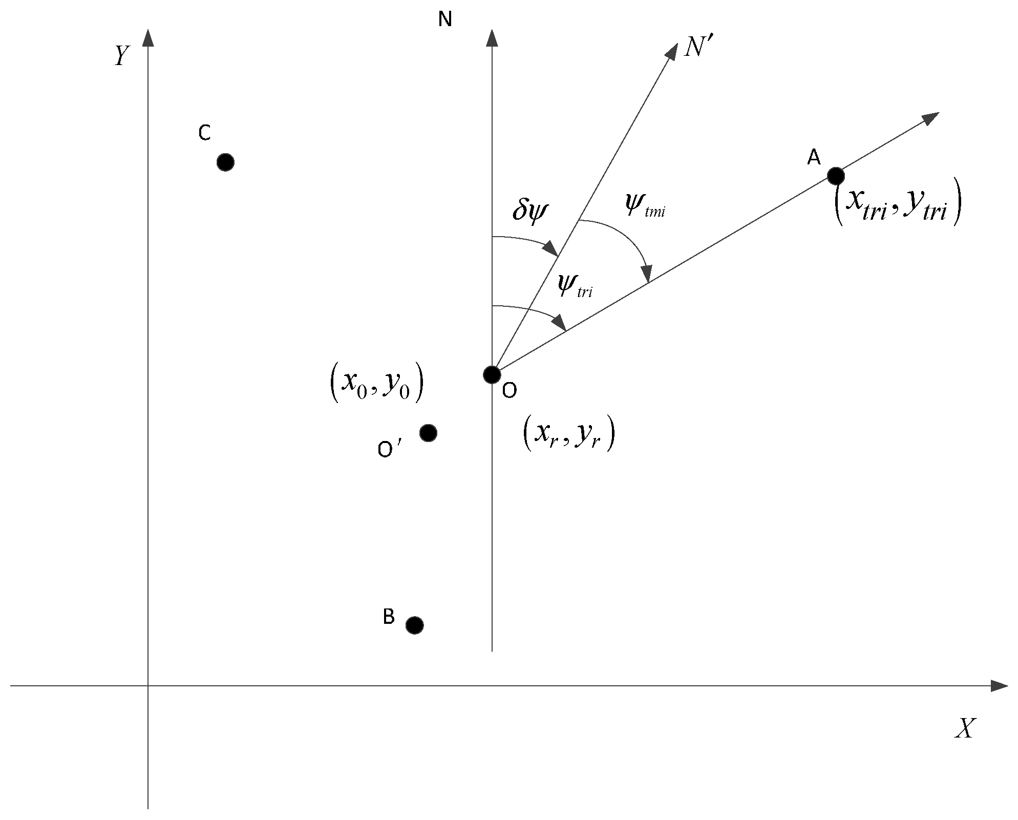
Establish a rectangular coordinate system shown in
Figure 1A–C are cooperative targets, and O is the vehicle’s parking position. Use
, i = 1, 2, 3 to denote the targets’ coordinates which are measured by DGNSS, and
i = 1, 2, 3 to denote the targets’ true coordinates. The vehicle based INS/DR provides vehicle’s coordinates as
, while the vehicle’s real coordinates are
. The direction
denotes true north of geographic coordinate system, and
denotes north direction given by INS/DR. Use
to denote the difference between
and
. The true attitude and azimuth of the vehicle are
respectively, and
are vehicle’s attitude and azimuth provided by INS/DR. The BODP aiming at the targets A, B, C and output three couples of azimuth and pitch angles denoted by
,
and
, while the true angles are denoted by
,
and
.
Figure 1.
Orientation and horizontal position determination diagram.
Figure 1.
Orientation and horizontal position determination diagram.
From geometric relations shown in
Figure 1, we can get the following equation:
Linearize Equation (1) by Taylor expansion at
as follows:
where
is the value of
at
, i = 1, 2, 3, and
Since coordinates of the cooperative targets A, B and C are acquired by precise measurement, compared to
and
,
and
can be ignored. Then, Equation (2) can be simplified as follows:
If three cooperative targets are measured, the corresponding equations can be written as following:
where
Then, the initial horizontal position and orientation errors can be calculated by the following Equation:
After calculating , use it to update and correct INS/DR positioning result (x0,y0) and orientation error , recalculate each target’s true azimuth relative to vehicle, and then use the corrected positioning and orientation results to do the same procedure, until each iteration correction is within the expected accuracy. By finishing the iteration, the horizontal position and orientation of the vehicle is accurately determined.
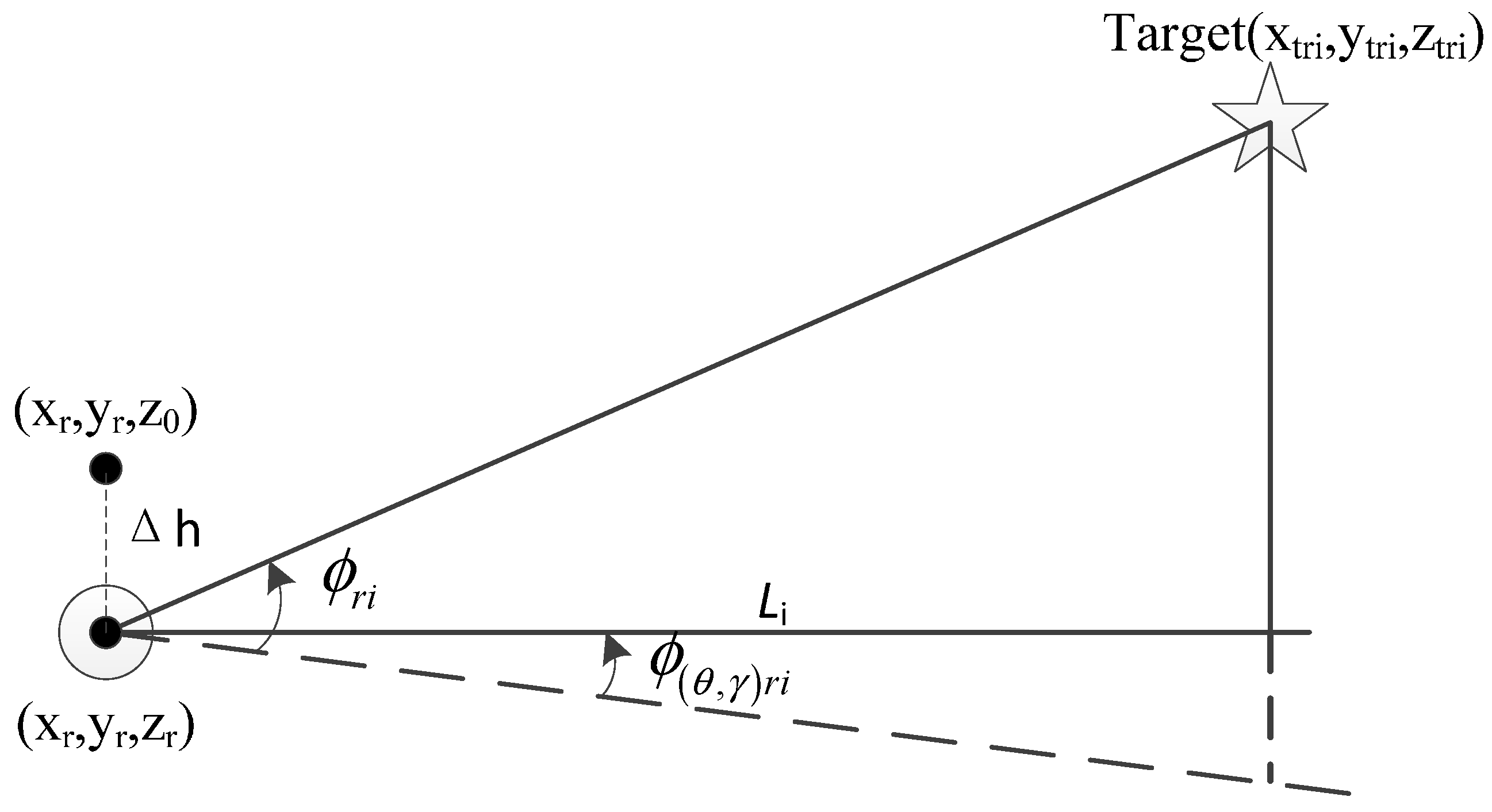
2.3. Attitudes and Height Determination Algorithm
In the proposed approach, the vehicle’s accurate attitudes and height determination algorithm is on the basis of orientation and horizontal position determination results. After acquiring the accurate horizontal position and orientation results in the previous section, their errors are assumed to be negligible when determining the vehicle’s attitudes and height.
The relationship of vehicle and targets’ position and angles measurements are shown in
Figure 2:
Figure 2.
Relationship of vehicle and target’s position and measurements.
Figure 2.
Relationship of vehicle and target’s position and measurements.
Where is the horizontal distance between vehicle and the ith target. is the true angle from optical axis of BODP when rotating around the vertical axis to the direction just below the target to the horizontal plane.
From the Euler angles rotation relationship and
Figure 2, the following equation can be derived:
In land vehicle missile-launching applications, usually relatively firm and flat areas are selected as launching point, and the attitudes of the vehicle are usually small angles. If attitudes errors provided by INS/DR are
and
, that is,
, then Equation (7) can be simplified as:
The BODP measured
is denoted by
, which is given by:
Use
to denote error of
, and
is given by:
From Equations (8)–(10), it can be seen that:
Assume
, where the pitch angle
is measured by BODP, then the following equation can be derived:
Since
is small angle,
, thus the following equation can be derived:
If three cooperative targets are measured, the corresponding equations can be written as following:
where,
Then, the initial height and attitudes errors can be calculated by the following equation:
After calculating , use it to update and correct INS/DR height and attitudes errors. And then use the corrected results to do the same procedure, until each iteration correction is within the expected accuracy. By finishing the iteration, the vehicle’s height and attitudes can be accurately determined.
4. Vehicle Experiments and Analysis
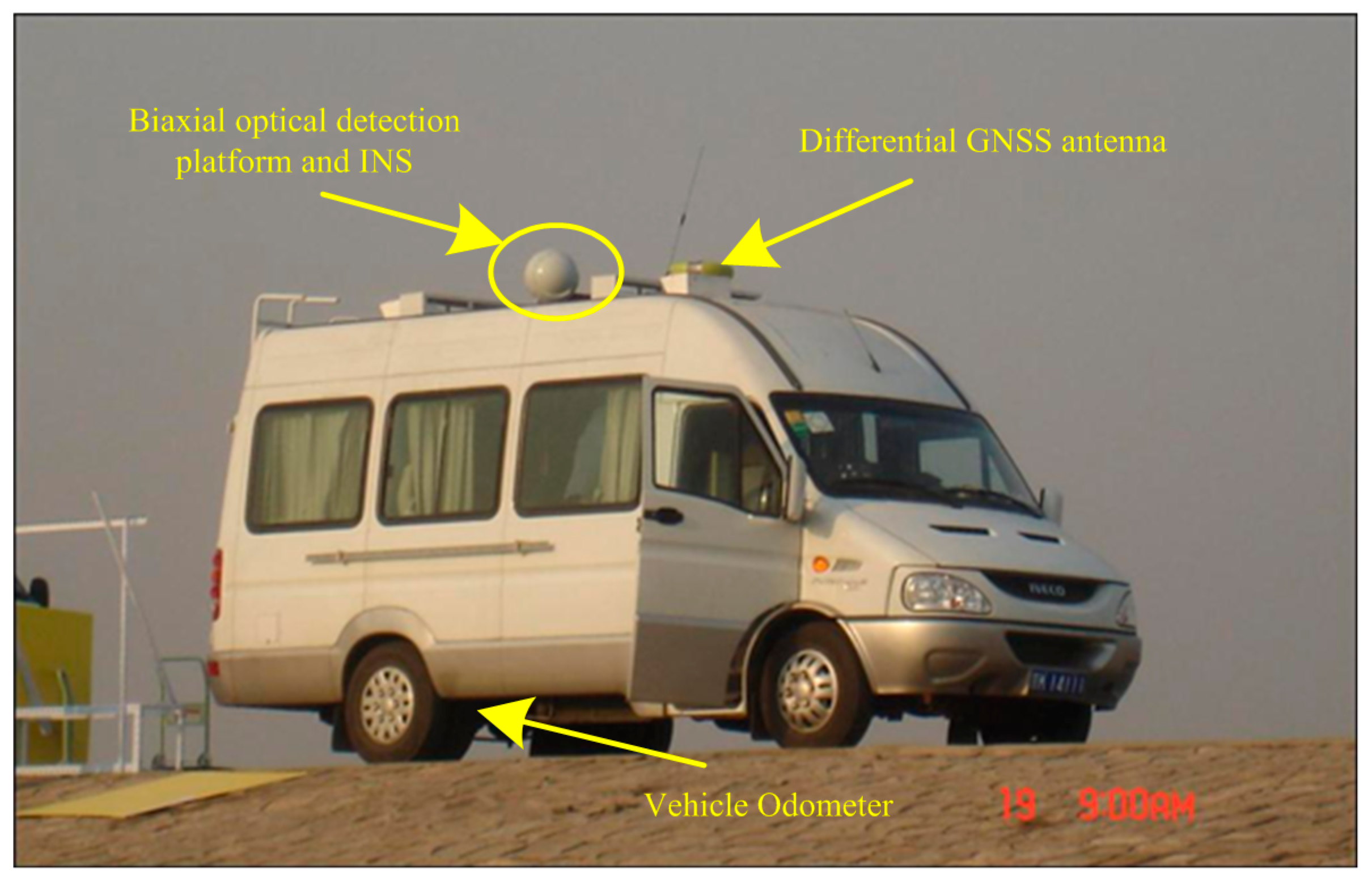
The proposed positioning and orientation system mainly consist of vehicle based equipment and cooperative targets. The vehicle-based equipment includes INS/DR integration system, a DGNSS receiver and a BODP. The experimental vehicle and relative equipment are shown in
Figure 10.
Figure 10.
Experimental vehicle and relative equipment.
Figure 10.
Experimental vehicle and relative equipment.
In the experiment, the odometer is chosen with 1024 pulse output when vehicle’s wheel rounding a whole circle. And the positioning accuracy of INS/DR is about 0.001 times of distance that vehicle moves. The BODP pitch and azimuth angles measuring accuracy are about 5″ when aiming at and locking the cooperative targets. The DGNSS positioning accuracy is about 0.02 m (1σ).
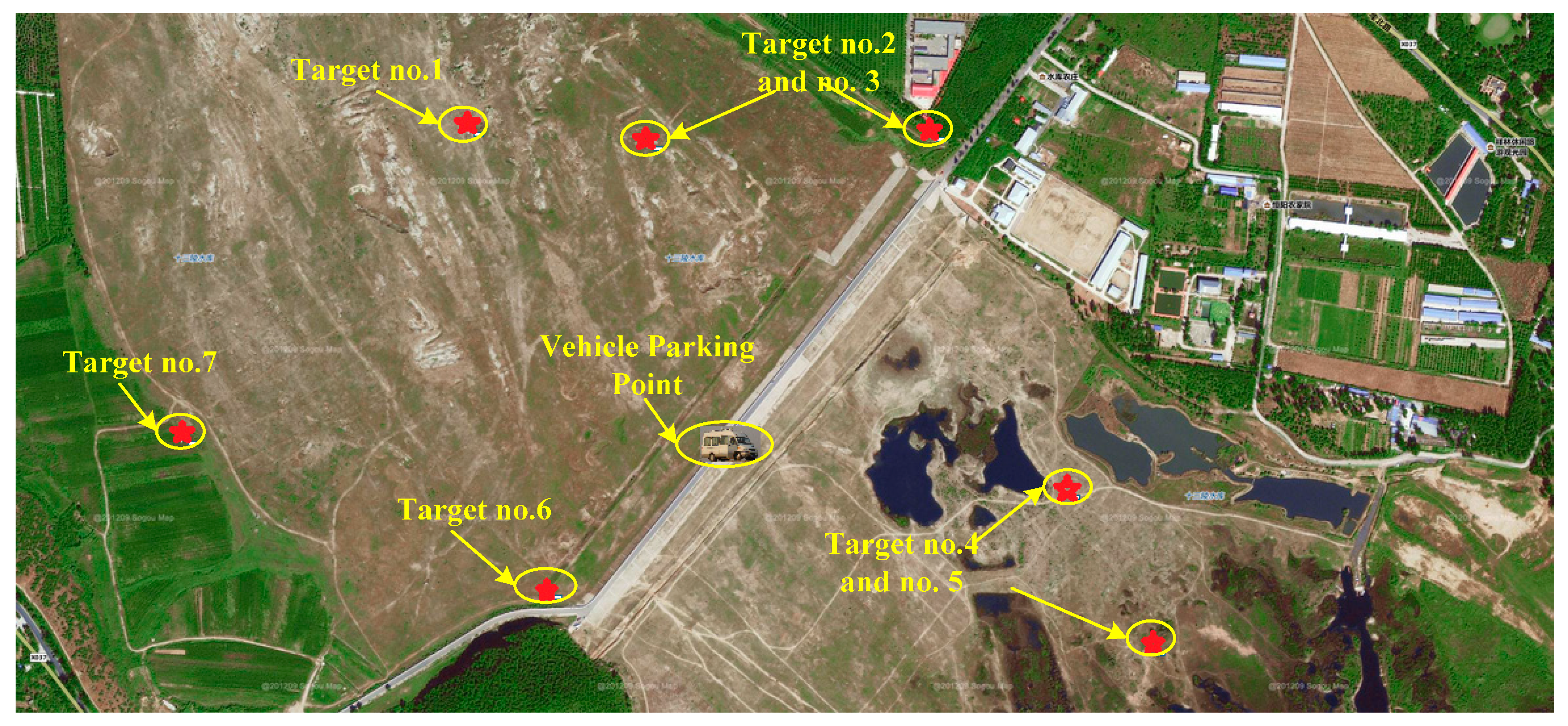
The experimental area is selected in the suburb of Beijing city. Seven cooperative targets are settled in the area, which are numbered as target no.1, 2…and 7. The distribution of the cooperative targets and vehicle parking point are shown in
Figure 11. The precise coordinates of all cooperative targets are measured by DGNSS. In addition, the vehicle is also equipped with DGNSS to provide reference position for algorithm evaluation.
Figure 11.
Distribution of the cooperative targets and vehicle.
Figure 11.
Distribution of the cooperative targets and vehicle.
The experimental vehicle is driven to the parking point from the starting point several kilometers away. Then, use the vehicle based DGNSS receiver to measure the vehicle’s precise position as reference. The DGNSS position measuring results of the targets and the vehicle parking point are given in
Table 1.
Table 1.
Positions of the targets and parking points.
Table 1.
Positions of the targets and parking points.
| | Longitude (°) | Latitude (°) | Height (m) |
|---|
| Parking point | 116.2469562 | 40.2683542 | 70.90 |
| Target no.1 | 116.2428290 | 40.2722016 | 79.20 |
| Target no.2 | 116.2454469 | 40.2717759 | 79.17 |
| Target no.3 | 116.2496097 | 40.2713175 | 84.10 |
| Target no.4 | 116.2515194 | 40.2676992 | 83.89 |
| Target no.5 | 116.2546308 | 40.2661110 | 80.13 |
| Target no.6 | 116.2443096 | 40.2664876 | 102.16 |
| Target no.7 | 116.2395675 | 40.2683541 | 89.23 |
After the BODP aims at and lock the targets, it would output azimuth and pitch angles relative to vehicle. Apply the proposed positioning and orientation approach to the equipment measurements, and then give the calculation results. In the experiment, the targets no. 2, 5, 7 were selected and the same experiment procedure was done seven times. Every time a new set of measuring parameters were acquired. Then, apply the proposed approach to seven sets of measurements and the results are given in
Table 2.
Table 2.
Positioning and orientation results
Table 2.
Positioning and orientation results
| | Longitude (°) | Latitude (°) | Azimuth (°) | Height (m) | Pitch (°) | Roll (°) |
|---|
| 1 | 116.2469543 | 40.2683567 | 39.0451 | 71.10 | −0.0677 | −2.0003 |
| 2 | 116.2469520 | 40.2683559 | 39.0475 | 71.08 | −0.0628 | −1.9984 |
| 3 | 116.2469550 | 40.2683559 | 39.0404 | 71.19 | −0.0677 | −2.0002 |
| 4 | 116.2469540 | 40.2683561 | 39.0441 | 71.20 | −0.0628 | −1.9978 |
| 5 | 116.2469541 | 40.2683569 | 39.0315 | 71.06 | −0.0661 | −2.0002 |
| 6 | 116.2469534 | 40.2683565 | 39.0450 | 71.92 | −0.0669 | −2.0006 |
| 7 | 116.2469518 | 40.2683555 | 39.0412 | 71.03 | −0.0632 | −1.9986 |
| Mean | 116.2469535 | 40.2683562 | 39.0421 | 71.23 | −0.0653 | −1.9994 |
| Std | 0.11 m | 0.06 m | 19.0″ | 0.31 m | 8.3″ | 4.1″ |
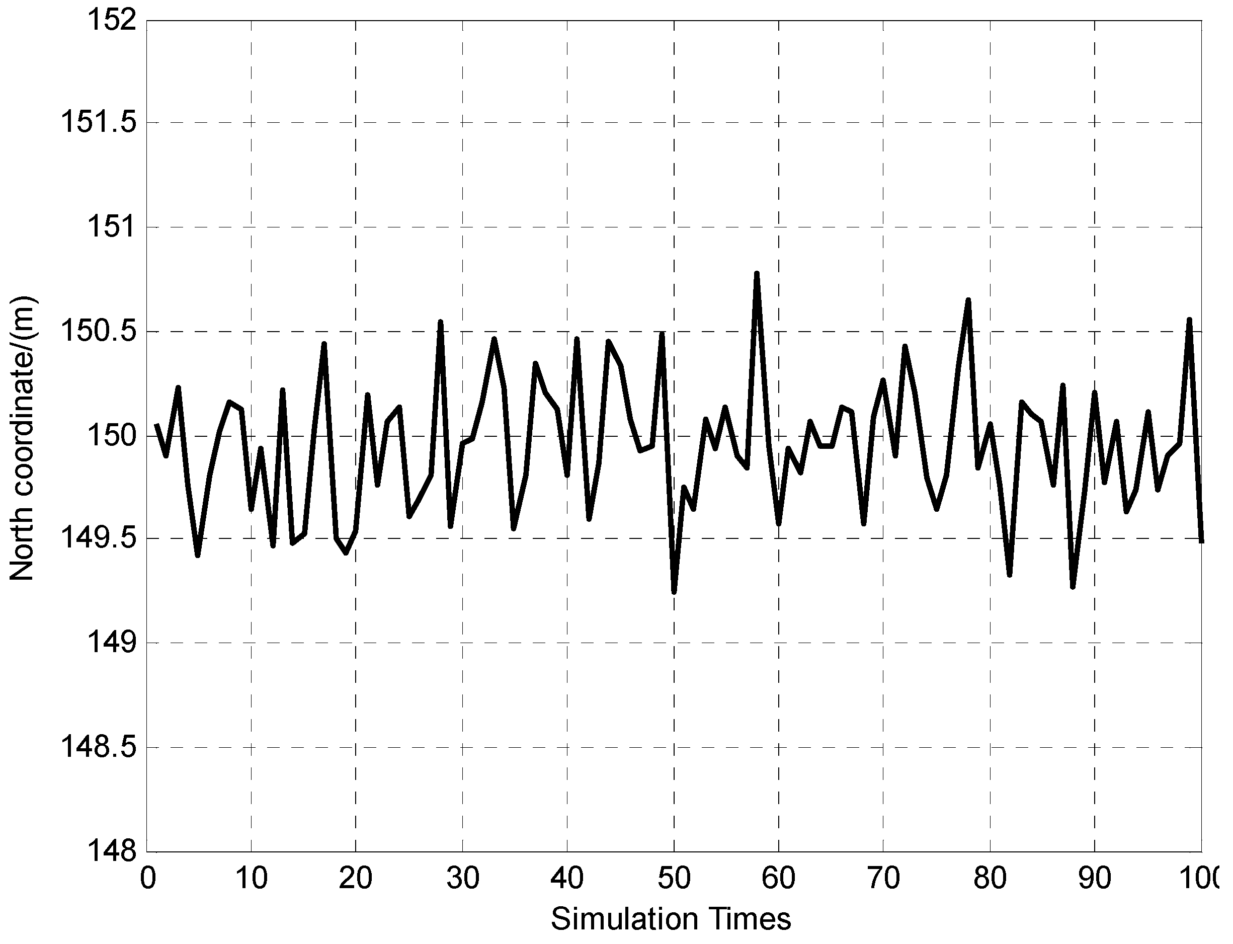
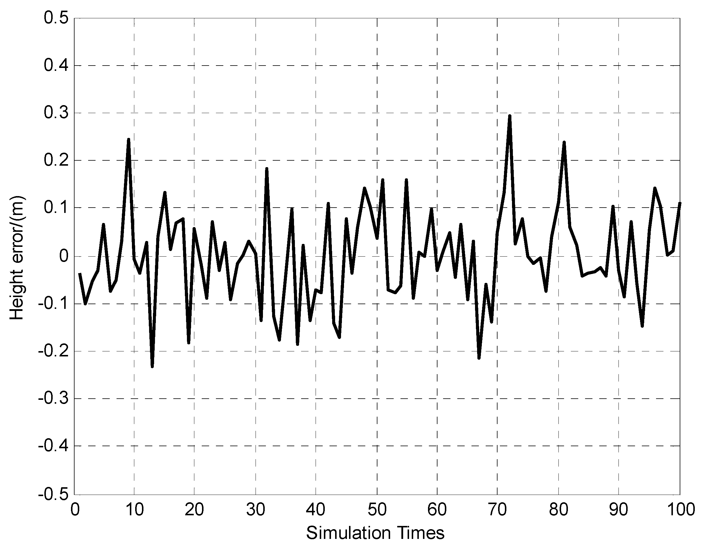
It can be seen from
Table 2 that in the seven experiments, the standard deviation of horizontal positioning and height errors are about 0.1 m and 0.3 m, and attitudes (pitch and roll) and orientation errors are about 8″ and 20″ respectively. The statistical results indicate that the proposed approach displays good repeatability. To further verify the effectiveness of the proposed approach, five different sets of targets were selected to form different groups of measurements. The five groups of targets combinations are targets no. 2,5,7 combination, targets no. 1,4,6 combination, targets no. 3,4,7 combination, targets no. 1,3,5 combination, and targets no. 2,4,6 combination respectively. The proposed approach was applied to the five combinations of targets, and the calculation results are given in
Table 3.
Table 3.
Positioning and orientation results using different combination of targets
Table 3.
Positioning and orientation results using different combination of targets
| Targets no. | Longitude (°) | Latitude (°) | Azimuth (°) | Height (m) | Pitch (°) | Roll (°) |
|---|
| No. 2,5,7 | 116.2469534 | 40.2683571 | 39.0409 | 71.11 | −0.0661 | −2.0000 |
| No. 1,4,6 | 116.2469549 | 40.2683563 | 39.0514 | 70.95 | −0.0715 | −2.0035 |
| No. 3,4,7 | 116.2469539 | 40.2683560 | 39.0331 | 70.93 | −0.0709 | −2.0021 |
| No. 1,3,5 | 116.2469560 | 40.2683555 | 39.0521 | 71.11 | −0.0642 | −1.9982 |
| No. 2,4,6 | 116.2469546 | 40.2683567 | 39.0310 | 70.70 | −0.0751 | −2.0063 |
| Mean | 116.2469546 | 40.2683563 | 39.0417 | 70.96 | −0.0696 | −2.0020 |
| Reference | 116.2469562 | 40.2683542 | | 70.90 | | |
| Max offset | 0.24 m | 0.32 m | 38.5″ | 0.21 m | 19.8″ | 15.5″ |
In
Table 3, the vehicle’s position provided by DGNSS is listed as reference. It can be seen that compared to the reference, the approach can achieve positioning accuracy of about 0.3 m maximum offset by using different sets of targets. Since there isn’t any other high performance azimuth and attitude measuring equipment in the vehicle during the experiments, the true azimuth and attitude reference are not acquired. In this circumstance, the mean attitude determination results are used as reference and only repeatability when using different groups of targets are evaluated. In addition, the results show that the azimuth maximum offset relative to mean value is 38.5″, and the maximum pitch and roll angles offset are 19.8″ and 15.5″, respectively.
In the verification experiments mentioned above, only three targets are selected for calculation. It takes about 40 s average to aim at and lock one target. If three cooperative targets are used and locked, the total time needed is about 2 min, but if more than three targets are used, it would take more time. In fact, if more preparing time is allowed, the system could aim at and lock more targets, and this approach could achieve better results.
Compared with other methods listed in the introduction, the vehicle experiments’ results proved that the proposed approach in this paper has many advantages. By using theodolite, it can acquire quite high orientation information (20″), but the operation of theodolite requires long duration (usually more than 20 min), and theodolite cannot provide position information either; however, the proposed approach in this paper is easy to operate and can obtain the same orientation accuracy as theodolite within 3 min as well as high accuracy positioning information.
The positioning accuracy of medium-accuracy of INS/DR is about several hundred meters while the orientation accuracy is about 3′. Compared to the INS/DR integration, the proposed approach improves the positioning and orientation accuracy significantly, with positioning error of less than 1 m and orientation error of about 20″. If the same positioning and orientation accuracy were to be acquired by INS/DR, the drifts of gyros employed in INS must be less than 0.001°/h, which will greatly increase the cost. However, the proposed approach only needs a rough position and orientation as an algorithm’s iterative initial value by INS/DR, so the cost can be reduced substantially.
The positioning accuracy of GNSS can be less than 1 m, but the GNSS signals are easy to interfere with and are requested not to be used during wartime. In addition, in order to achieve 20″ orientation information by GNSS, multiple GNSS antennas and long base line (several decameters) are needed; it is not easy to operate in practical situation. Therefore, the proposed approach has obvious advantages in positioning and orientation accuracy, rapidity, autonomy and cost; consequently, the approach has considerable potential in rapid and accurate positioning and orientation applications for land missile-launching vehicles.


