If one of the IMU outputs,
for example, is known, the angle between the
-axis and
can be computed. If
is also given, the angle between the
-axis and
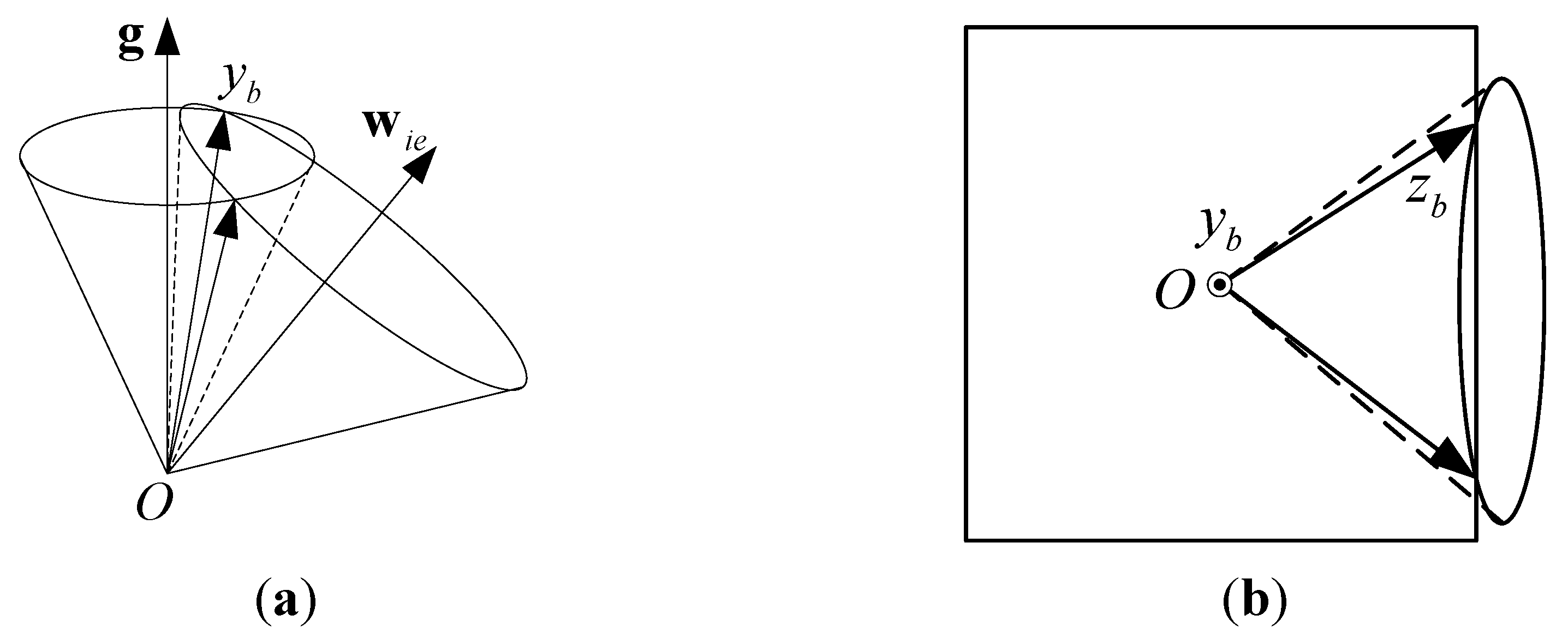
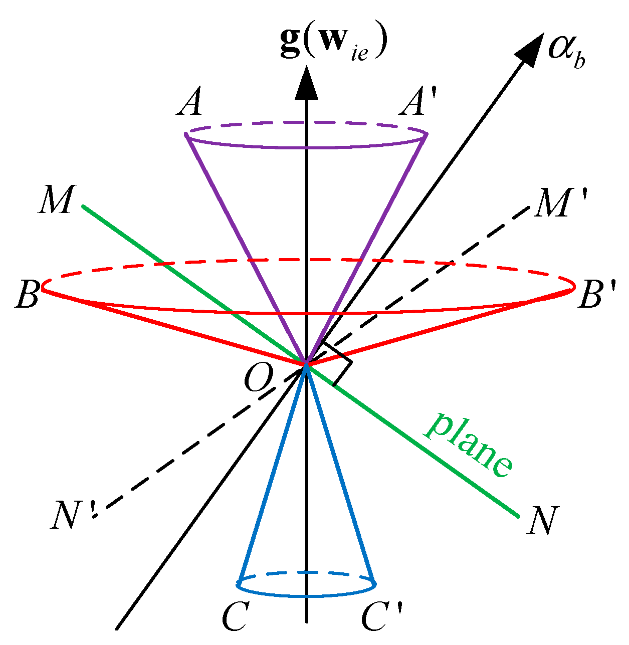
can be determined. As shown in
Figure 2a, there are two possible solutions for the
-axis because usually there will be two lines of intersection between the two conical surfaces.
After the
-axis is obtained, the
frame can be obtained if one more axis is computed. For example, if
is also known, the
-axis will be on the conical surface with its center at
. In addition, because the
-axis is normal to the
-axis, the
-axis must be in the plane that is normal to the
-axis. There are usually two lines of intersection of a plane and a conical surface that represent the
-axis, as shown in
Figure 2b.
Figure 2.
Existence of the selective alignment solution: (a) Two lines that represent the -axis will be formed by the intersections of the two conical surfaces; (b) Two lines that represent the -axis will be formed by the intersection of a plane and a conical surface.
3.1. Derivation
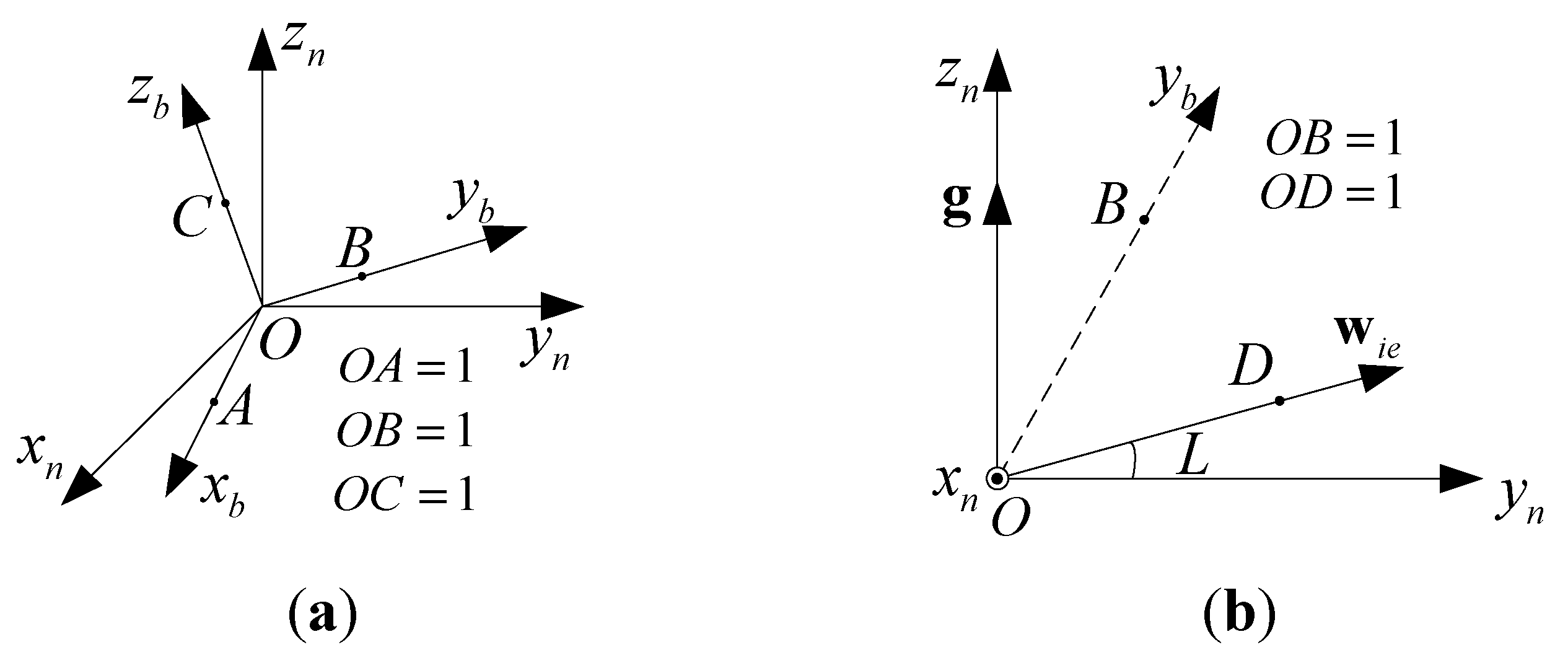
Now let us derive mathematical expressions for the four solutions of
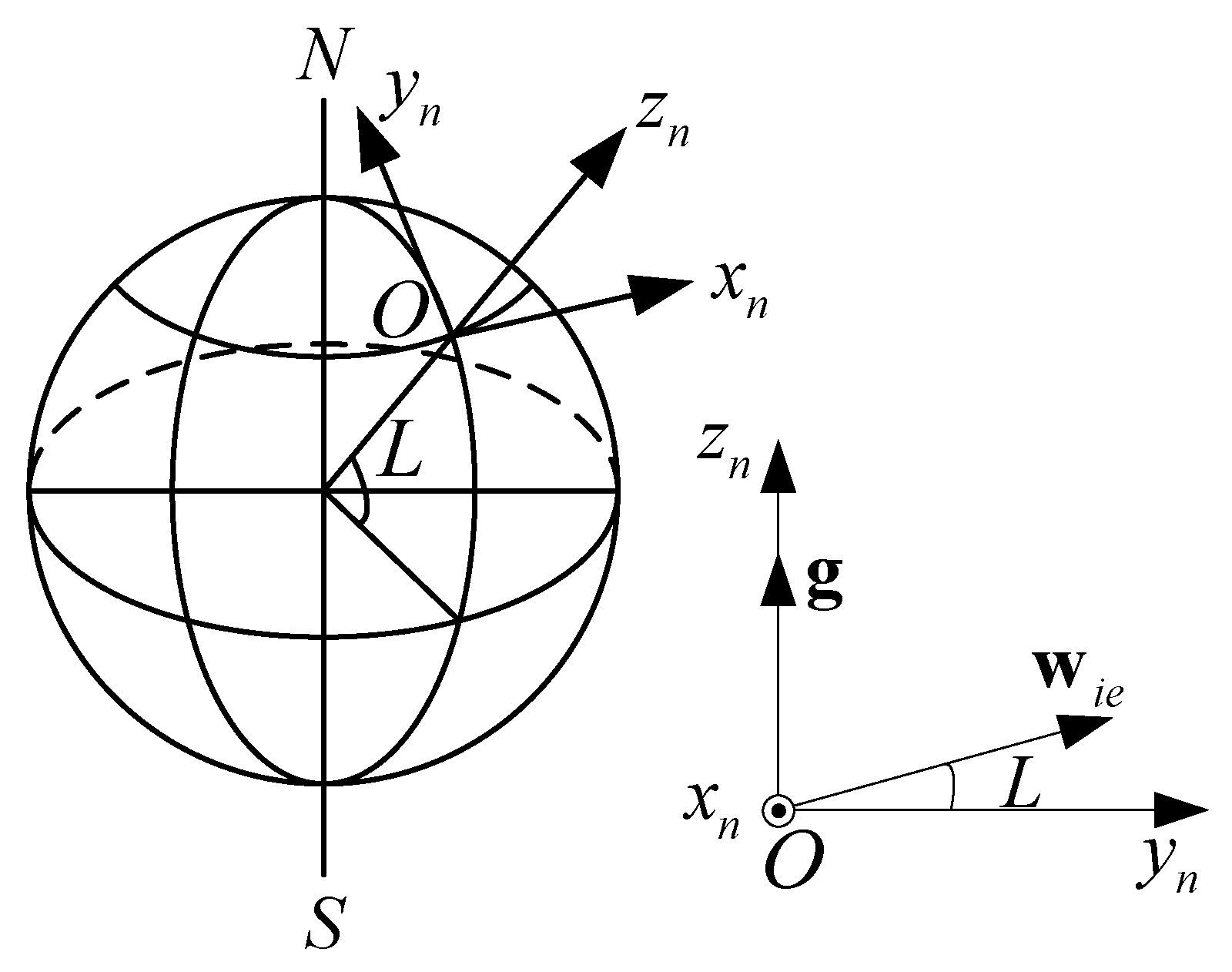
. As shown in
Figure 3a,
denotes the navigation coordinates, as indicated by the subscript
, and
denotes the body coordinates, as indicated by the subscript
. Let
,
, and
be coordinates in the navigation frame, and let
,
, and
be coordinates in the body frame. After ascertaining
,
can be obtained by
Figure 3.
(a) The definitions of , , and ; (b) , namely, the -axis, can be determined given and . Here, the -axis is not usually in the plane.
Figure 3.
(a) The definitions of , , and ; (b) , namely, the -axis, can be determined given and . Here, the -axis is not usually in the plane.
Assume three outputs of the IMU are given, which are
,
, and
. If
is given, as shown in
Figure 3b, we have
Referring to
Figure 3b, in the navigation frame the following equation holds:
Because
and
are unit vectors and
, substituting Equation (8) into Equation (9) gives
If
is given, the angle between
and the
-axis is known, which implies
Combining Equations (10) and (11), and
yields
Solving Equation (12) yields two sets of solutions:
Similarly, if
is given, we have
As shown in
Figure 3a, because
is the unit vector of the positive
-axis and
, the following equations hold
Solving Equation (15) yields two sets of solutions
where
.
Then,
can be obtained as shown in Equation (17)
Hence, from Equation (7), can be obtained. There are four sets of solutions for given , and .
Next, we consider the case where
,
and
are given. Likewise, given
rather than
, we have
Because
is the unit vector of the positive
-axis and
, the following equations hold
Solving Equation (19) yields two sets of solutions
where
.
Therefore,
is given by
Hence, can be obtained from Equation (7). There are four sets of solutions for given , , and .
The coordinate transformation matrix has been derived in two typical cases. For both cases, one output of the three-axis accelerator and one output of the three-axis gyroscope, both in the same axis, should be selected. The case where the remaining measurement is another output of the three-axis gyroscope is denoted by FWW, e.g., , , and , and the case where the remaining measurement is another output of the three-axis accelerator is denoted by FWF, e.g., , , and .
There are six possible sets for FWW and six possible sets for FWF, as shown in
Table 1.
Table 1.
The six possible sets for FWW and FWF.
Table 1.
The six possible sets for FWW and FWF.
| | | 1 | 2 | 3 | 4 | 5 | 6 |
|---|
| | Output 1 | | | | | | |
| | Output 2 | | | | | | |
| FWW | Output 3 | | | | | | |
| FWF | Output 3 | | | | | | |
For FWW, the three selected outputs are denoted as
,
and
, where the subscripts
,
and
represent
,
or
and should be different. The body frame is given by
where
a,
b and
c in Equation (23) are
,
in Equation (24) denotes
or
or
and
in Equation (24) denotes
or
or
.
For FWF, the three selected outputs are denoted as
,
and
. The subscripts
,
and
denote
,
or
and should be different. The body frame is given by Equations (22), (24), and (25):
where
,
, and
in Equation (25) are
.
3.2. Choice of Solutions
After ascertaining , can be obtained from Equation (7). There are four possible solutions, but only one is appropriate. Given the four possible solutions of , the vectors and can be computed from Equation (5). Comparing the calculated values of and with the original six outputs of the IMU, the appropriate solution can be easily ascertained amongst the four possible solutions.
To demonstrate the method for choosing the correct solution among the four possible solutions, one group of simulated outputs are used with
,
, and
.
,
, and
are selected to compute the attitude through the selective alignment method. Given the four possible solutions of the attitude (namely,
), the four possible sets of the six outputs can be computed from Equation (5), which are shown in
Table 2.
Table 2.
The four possible sets of six inertial measurement unit (IMU) outputs calculated with , , and used for selective alignment according to Equations (22)–(24).
Table 2.
The four possible sets of six inertial measurement unit (IMU) outputs calculated with , , and used for selective alignment according to Equations (22)–(24).
| | Angular Velocity () | Specific Force () |
|---|
| | | | | | | |
| 1 | −0.2550 | 0.6782 | 0.0824 | −3.1497 | 3.3518 | 8.6536 |
| 2 | 0.2550 | 0.6782 | 0.0824 | 7.6192 | 3.3518 | −5.1724 |
| 3 | 0.2550 | 0.6782 | 0.0824 | 3.1497 | 3.3518 | 8.6536 |
| 4 | −0.2550 | 0.6782 | 0.0824 | −7.6192 | 3.3518 | −5.1724 |
| Original outputs | −0.2550 | 0.6782 | 0.0824 | −3.1497 | 3.3518 | 8.6536 |
It is easy to discern that the attitude for Set 1 in
Table 2 is the correct solution by comparing the calculated and measured values of the outputs using one of the following sets of criteria:
The values compared will depend on the outputs selected. Through the selective alignment method, the attitude can be determined from any three outputs of the IMU in
Table 1 in addition to at least one force component and one angular velocity component in the same axis. Some limited information from the remaining three outputs such as the signs and approximate value is also essential. Furthermore, if, for example,
,
, and
are known,
can be calculated from Equation (26). Then, the attitude by the selective alignment method can be obtained.


