Nonlinear Magnetoelectric Response of Planar Ferromagnetic-Piezoelectric Structures to Sub-Millisecond Magnetic Pulses


Abstract
: The magnetoelectric response of bi- and symmetric trilayer composite structures to pulsed magnetic fields is experimentally investigated in detail. The structures comprise layers of commercially available piezoelectric (lead zirconate titanate) and magnetostrictive (permendur or nickel) materials. The magnetic-field pulses have the form of a half-wave sine function with duration of 450 μs and amplitudes ranging from 500 Oe to 38 kOe. The time dependence of the resulting voltage is presented and explained by theoretical estimations. Appearance of voltage oscillations with frequencies much larger than the reciprocal pulse length is observed for sufficiently large amplitudes (∼1–10 kOe) of the magnetic-field pulse. The origin of these oscillations is the excitation of bending and planar acoustic oscillations in the structures. Dependencies of the magnetoelectric voltage coefficient on the excitation frequency and the applied magnetic field are calculated by digital signal processing and compared with those obtained by the method of harmonic field modulation. The results are of interest for developing magnetoelectric sensors of pulsed magnetic fields as well as for rapid characterization of magnetoelectric composite structures.1. Introduction
Magnetoelectric (ME) interactions in planar composite structures comprising mechanically coupled ferromagnetic (FM) and piezoelectric (PE) layers have been investigated intensively in recent years due to the prospects of their application as sensitive magnetic field sensors [1–3]. The functional principle of a ME sensor is as follows: when the structure is placed into the magnetic field, the magnetostriction causes a deformation of the FM layer. This strain is passed to the PE layer and a voltage is generated between the electrodes of the PE layer due to the PE effect. This voltage is proportional to the measured field strength. To create sensors for various types of magnetic field, detailed studies of the behavior of ME structures in weak low-frequency harmonic fields, in static magnetic fields and in pulsed magnetic fields are needed.
From the literature it is clear that the behavior of ME structures in harmonic low-frequency magnetic fields has already been intensively investigated. It was shown that the amplitude of the voltage u generated by ME structure in a weak harmonic field is proportional to d × q × δh, where d is the PE coefficient of the PE layer, q = ∂λ/∂H is the piezomagnetic coefficient, H is the magnetic field strength, λ is magnetostriction of the FM layer and δh is the amplitude of the alternating magnetic field. The voltage u reaches its maximum when a bias magnetic field Hm, at which the coefficient q takes its largest value, is applied to the structure. Hm is usually in the order of few Oe to a few kOe, depending on the properties of the FM layer. The voltage amplitude increases further at 1–2 orders of magnitude when the field frequency coincides with a frequency of acoustic oscillations of the structure due to the resonant enhancement in the PE strain [4]. Feasibility of making sensors for alternating magnetic fields with a detection limit down to ∼10−10 T [5] in the frequency range 1 mHz–10 kHz [6,7] employing composite structures with different material compositions and geometries was demonstrated. An equivalent magnetic noise floor of ∼10−1–101 pT·Hz−1/2 at a resonance frequency of ∼250 Hz was recently achieved using thin-film [8] and lamination [9] technologies. It was also shown that a cross-modulation scheme can shift low-frequency signals to a higher frequency in order to achieve a lower noise floor [10].
When the ME structure is placed into a permanent or slowly varying field H(t) with a large amplitude, the magnetostriction causes a quasi-static deformation of the PE layers, the appearance on their electrodes of bound charges Q and a corresponding DC voltage. In this case the voltage is proportional to the magnetostriction u(H)∼d × λ(H). Initially it grows with increasing H and then reaches a constant level at field strengths where the magnetostriction saturates. At the same time, due to the finite conductivity of the PE layers in the structure, a partial compensation of bound charges by free charges takes place, leading to reduction of the resulting voltage across the electrodes of the structure with time [6]. Therefore, the voltage across the electrodes of the FM-PE structure placed into a constant or slowly varying magnetic field of large amplitude depends not only on the field strength, but also on the time of measurement. For this reason, ME structures are less suitable for creating sensors for static or slowly varying magnetic fields.
Only a few experimental studies [11–15] have been devoted to the transient behavior of ME materials and structures in pulsed magnetic fields. For the first time the generation of voltage pulses with amplitudes up to 70 mV has been observed at the electrodes of a single crystal Cr2O3 when this crystal was magnetized with pulses of duration ∼1 ms and an amplitude of up to 4 kOe [11]. In [12] the generation of an alternating voltage with a frequency equal to the frequency of the planar acoustic oscillations was observed in the ceramic structure consisting of alternating layers of nickel-zinc ferrite and lead zirconate titanate (PZT), when it was exposed to field pulses of small amplitude Ĥ∼10–100 Oe with the length of 1–100 μs. Additionally the structure was tangentially magnetized with a bias field H ≈ 250 Oe. Note that the pulses were short, i.e., the frequency of the acoustic oscillations was smaller than the reciprocal pulse length. The possibility of applying such a technique combined with the Fourier transform to measurements of the frequency characteristics of ME structures in the frequency range from tens of Hz to several MHz was demonstrated [13]. In [14,15] a sample of a bulk ceramic composite containing a mixture of cobalt ferrite and barium titanate particles was magnetized by pulses of duration 4–50 ms with a peak-to-peak value of up to 50 kOe and the voltage pulses generated by the structure were recorded. According to the measurements obtained dependence of the efficiency of ME interaction on the field reached a maximum of ≈ 5.5 mVOe−1cm−1 in fields of ≈ 2–5 kOe. Hysteresis between the generated voltage and magnetic field strength has been measured. The authors explained this hysteresis by the strong influence of the charge compensation processes in the PE phase of the composite.
The purpose of this paper is a study of the ME response of planar FM-PE structures to magnetic-field pulses with fixed duration in a sub-millisecond range. The most interesting case when the pulse amplitude exceeds the saturation field of the FM layer and various types of acoustic oscillations in the structures are excited is considered. No bias magnetic field is applied. The pulse length is sufficiently short for neglecting the charge compensation due to the finite conductivity of the PE layer. On the other hand, the magnetic pulse is much longer than the period of observed oscillations. As the object of studies the structures containing layers of commercially available cobalt-iron alloy (CoFe) or nickel (Ni), possessing high magnetostriction and large enough saturation fields, and the layers of PZT ceramics, having large piezoelectric modulus, are selected. The paper starts with the description of the samples and the research methodology. Then the results of measurements together with their discussion and theoretical estimates are presented. The possibility of using the described pulsed technique for rapid characterization of ME interactions in composite structures is demonstrated. In conclusion the main findings of the work are summarized and the recommendations for the use of ME structures for the measurement of pulsed magnetic fields are given. The notation used in the paper is summarized in Appendix Table A1.
2. Samples and Measurement Methodology
Measurements were made on bi- and symmetric trilayer structures, containing layers of FM metallic materials (CoFe alloy or Ni) and the piezoceramic layer of PZT: CoFe/PZT, Ni/PZT, CoFe/PZT/CoFe and Ni/PZT/Ni (see Figure 1). The FM layers were made from either CoFe alloy VACOFLUX50® (permendur with the nominal composition Co0.49Fe0.491V0.019, manufacturer Vaccumschmelze GmbH & Co. KG, Hanau, Germany) or Ni (Ni201, manufacturer ATI Allegheny Ludlum, Remscheid, Germany). The PE layers were made from the PE ceramics VIBRIT® 1100 (manufacturer Johnson Matthey Catalysts, Redwitz, Germany). Layers of FM materials and PE ceramics had the following planar dimensions: length L = 10 mm, width b = 5 mm. The thickness of FM layer am was 0.35 mm for CoFe and 0.5 mm for Ni, the thickness of PZT ap = 0.5 mm. The surfaces of the PZT layer were coated with Au electrodes before being poled perpendicularly to its plane. The FM plates and PZT layer were bonded mechanically by an epoxy adhesive. The arrows in Figure 1 show the direction of the magnetization of the FM layer and the direction of the polarization of the PE layer. This is the so-called L-T configuration [16]. The magnetic field was applied in the plane of the samples along the long side of the structures. The voltage pulses u(t) generated by the structures were measured between the electrodes of the PZT layers.
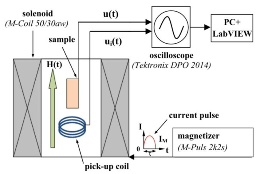
The block diagram of the measuring apparatus is shown in Figure 2. The sample was placed inside the solenoid of a conventional magnetizer M-Pulse 2k2s with M-Coil 50/30aw (M-Pulse GmbH & Co. KG, Kierspe, Germany). Magnetic-field pulses H(t) had the form of a half-wave sine function with a constant duration τ = 450 μs and amplitudes between 500 Oe and 38 kOe. In order to measure the shape and the magnitude of the field pulses, the pick-up coil (3 turns of copper wire with a diameter of 0.3 mm) with a diameter of 11 mm was placed inside the solenoid in the vicinity of the sample. Time-dependence of the magnetic field H(t) was determined by integrating the voltage ui(t) induced in the pick-up coil. The voltage pulses with an amplitude of up to 27 V generated by a PZT layer were recorded using a digital storage oscilloscope Tektronix (DPO 2014) with the input resistance of 10 MΩ. The data files contained up to 125 × 103 points.
The frequency spectrum of the voltage pulse g(f) was calculated using the discrete Fourier transform function in LabView. For all CoFe samples the dependencies of the ME conversion coefficient on the frequency f at DC bias field Hm and at fixed frequency f on the DC field H were also obtained by the standard method of harmonic field modulation (HFM) (δh = 1 Oe, f = 100 Hz–300 kHz, bias field Hm = 650 Oe) [17].
3. Results and Discussion
3.1. Measurement Results
Figure 3 shows the evolution of both the time dependence u(t) and the frequency spectrum g(f) of the voltage pulse u(t) generated by the CoFe/PZT structure dependent on the amplitude Ĥ of the exciting magnetic-field pulse H(t).
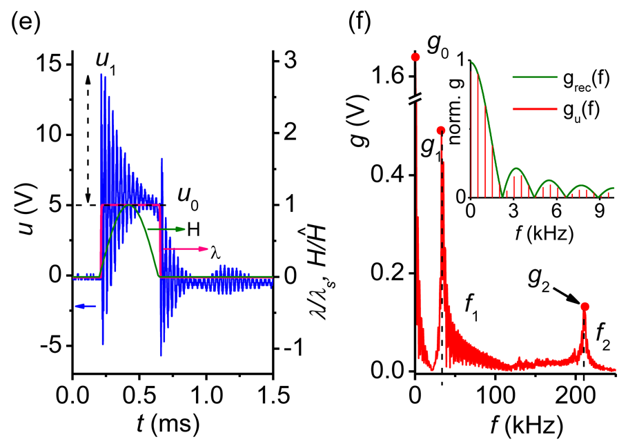
With the increase of the amplitude of the field pulse its shape H(t)/Ĥ and frequency spectrum remain practically unchanged. For Ĥ < 1.5 kOe the shape of the voltage pulse u(t) follows the time dependence of the field strength H(t). When Ĥ is increased up to ≈ 1.5 kOe, a voltage pulse with a flat top starts to form (Figure 3(a,b)). The insets in the right column of Figure 3 illustrate how the low-frequency (f < 9 kHz) part of the voltage pulse spectrum changes from a half-sine pulse to a rectangular pulse. The amplitude u0 of the generated pulse reached ≈ 5 V. With further increase of Ĥ the damped oscillations of the voltage pulse have been observed on its flat top and immediately after the end of the excitation pulse. These oscillations have the initial amplitude u1 (Figure 3(c)) and the harmonic frequency f1 ≈ 33 kHz (Figure 3(d)) in the frequency spectrum. As shown below, these low-frequency oscillations with frequency f1 correspond to the excitation of flexural acoustic oscillations of the structure. For the excitation pulse amplitudes Ĥ ≥ 11 kOe, the high-frequency oscillations of u(t) with frequency f2 ≈ 210 kHz and amplitude u2 (Figure 3(e)) have appeared additionally on the top of the pulse and immediately after excitation which is clearly visible in the spectrum of the signal (Figure 3(f)). These high-frequency oscillations, as it will be shown below, are caused by the excitation of the planar acoustic oscillations in the structure. Acoustic oscillations enhance deformations in the PE layer (electromechanical resonance) leading to voltage values higher than the ME voltage resulting from quasi-static magnetostriction.
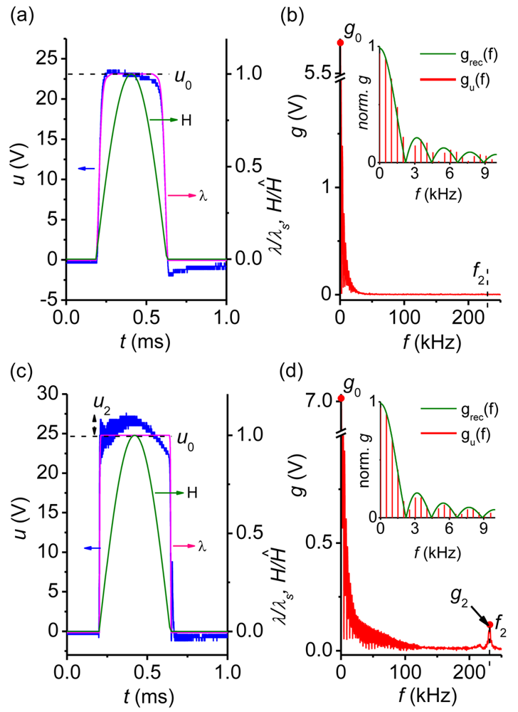
Figure 4 presents the evolution of both the time function u(t) and the frequency spectrum g(f) of the voltage pulse with growing amplitude Ĥ of the exciting magnetic field H(t) in the symmetrical trilayer structure CoFe/PZT/CoFe. In this case only a gradual formation of the flat top pulse (Figure 4(a)) with an amplitude of up to u0max ≈ 24 V and the broadening of its spectrum occurred with increasing Ĥ (Figure 4(b)). The insets in the right column of Figure 4 demonstrate that the low-frequency part of voltage pulse spectrum is close to a rectangular pulse. The lack of low-frequency oscillations with frequency f1 is explained by the low efficiency of excitation of the flexural acoustic oscillations in a symmetric structure. As seen in Figure 4(c) and in the frequency spectrum of Figure 4(d) the high-frequency modulation of the generated pulse corresponding to the excitation of planar acoustic oscillations with frequency f2 ≈ 230 kHz appeared only at large Ĥ ≥ 17 kOe.
3.2. Discussion and Numerical Estimates
Figure 3(a,c,e) and Figure 4(a,c) (right axis) also present the calculated time dependence λ(H(t)) × λs−1 where λ = λ11 + λ12 is the magnetostriction coefficient, λs = λS,11 + λS,12 is the saturation magnetostriction and λ11, λ12 are the longitudinal and transversal magnetostriction coefficients, respectively. The dependencies λ11(H) and λ12(H) were measured by the strain-gauge method [17]. It is seen that the running average of u(t) follows the time variation of λ(H(t)) × λs−1 very well. In the quasi-static regime the voltage generated by the layered structure depicted in Figure 1 is proportional to the magnetostriction: u(t) = uomax × λ(H(t)) × λs−1, with uomax depending on the material parameters and the geometry of the sample. From Figures 3 and 4 one gets u0max ≈ 4.8 V and 24 V for bi- and symmetric trilayer structures, respectively. If the magnetostriction is driven into saturation an almost rectangular pulse u(t) is generated. An observed slow decay of u(t) at the pulse top in Figure 4(a) can be attributed to the electrical relaxation processes in the PE layer [18,19].
The maximum value u0max of u(t) for the symmetric trilayer structure is almost five times larger than that for the bilayer structure. It is achieved when the magnetostriction of the FM material is saturated. Assuming homogeneity of the internal magnetic field in the FM layer and uniform stress over the thickness and plane of the structure, the following expression can be obtained for a symmetric trilayer structure in the low-frequency range [20,21]:
Substituting the known parameters of FM and PE layers into Equation (1) u0max = 33 V is obtained. Despite of the approximations there is good agreement with the experimental results. Note that a one-dimensional theory [16,22] underestimates u0max (u0max = 17.9 V). Equation (1) cannot be directly applied to a bilayer structure due to the bending of the bilayer sample. The much lower value of u0max for a bilayer structure can be qualitatively explained in the following way. First, the amplitude is decreased, since the thickness of the FM material is halved. Formal substitution in Equation (1) gives a 20% decrease in amplitude. Hence, the voltage is decreased mainly as a result of bending of the sample. It is known that in pure bending the mechanical strains vary linearly over the thickness of the structure: there is compression at one surface and expansion at the other surface, the plane with zero strain (the middle plane) lies inside the sample. If the thickness and compliance of the FM and PE layers were identical, then this plane would be held exactly in the middle of the structure. Then the electric field across the thickness of PE layer would change linearly, with maximum at the free surface and zero at the inner surface. In this case (because of the linearity of the field distribution) the voltage between the electrodes would be further diminished by a factor of 2. Due to the bending the middle plane is actually located inside the PE layer at a distance of ≈ 37.4 μm from the bilayer interface [23]. The electric field changes its sign inside the PE layer, and (after integration over the thickness) there will be even less voltage between the electrodes.
The oscillations of u(t) cannot be explained by the quasi-static theory. The observed oscillation frequencies are much larger than τ−1. To the best of our knowledge, in the absence of bias field and with long excitation pulses such oscillations are observed experimentally for the first time. We are aware of only one paper [24] reporting a similar phenomenon as a result of numerical modeling.
The oscillations of u(t) could only be detected if the amplitude Ĥ exceeds a certain threshold value (compare right columns in Figures 3 and 4). The oscillations of u(t) start practically from the beginning of H(t) and not after λ(t) reaches saturation. The second impetus to these oscillations is caused by the trailing edge of H(t).
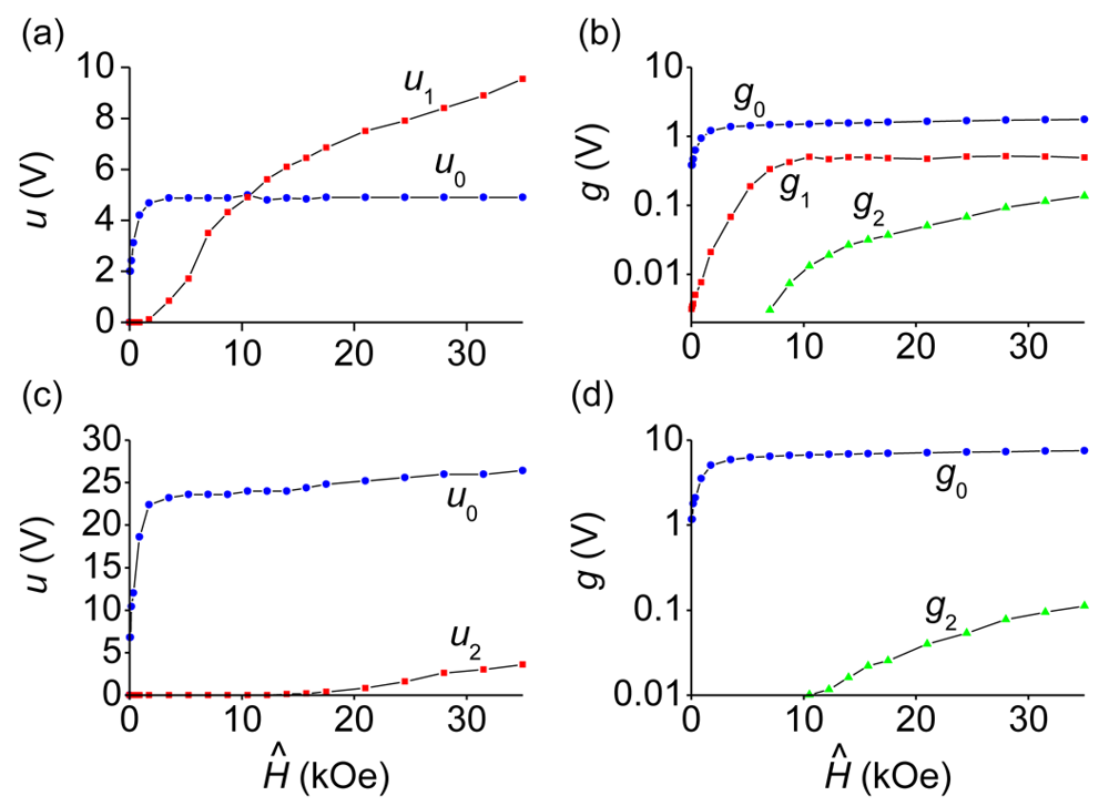
Figure 5 shows the dependencies quantitatively characterizing the response of planar bi- and trilayer FM-PE structures on the magnetic pulse with the increasing amplitude Ĥ. These dependencies are plotted using data similar to those presented in Figures 3 and 4. It can be seen that for the CoFe/PZT structure the amplitude of the generated pulse initially rises sharply with the increasing Ĥ and then reaches saturation u0 ≈ 4.8 V at a field strength Ĥ ≈ 1.5 kOe. The clipping of the pulse amplitude is attributed to the saturation of magnetostriction in the CoFe layer, which occurs just at field strengths of kOe. At the same time, the amplitude of the low-frequency oscillation u1 and the amplitude of the corresponding harmonic g1 in the signal spectrum are increasing. At a field strength of Ĥ ≈ 6 kOe the amplitudes u1 and g1 reach saturation. At the same field strength the high-frequency oscillations at the frequency f2 with the amplitude u2 and the amplitude g2 of the corresponding harmonic in the spectrum continue to monotonically increase with growing Ĥ. For the CoFe/PZT/CoFe structure the amplitude of the generated pulse initially increases with the rising Ĥ and then is limited at u0 ≈ 24 V when ĤS ≈ 3.5 kOe. The increase of the limiting field of the pulse amplitude, as compared with two-layer structure, is due to the increment in the total thickness of the ferromagnet, resulting in an increase of the demagnetization field [25]. When the field pulse amplitude reaches Ĥ ≈ 17 kOe, high-frequency oscillations appear at the top of the electrical pulse. The amplitude u2 of these oscillations and the harmonic amplitude g2 in the spectrum continue to grow with increasing amplitude of the field pulse.
The growth of the oscillation amplitudes u1 and u2 with the increasing excitation pulse magnitude Ĥ, even after the pulse amplitude u0 was saturated (see Figure 5), can be explained as follows. For the magnetic pulse of fixed duration, the increase of the magnitude Ĥ results in the corresponding growth of the magnitudes of harmonics with frequencies f1 and f2 in its frequency spectrum. The higher are the magnitudes of these harmonics, the more efficient is the excitation of bending and planar acoustical oscillations of the sample leading to the higher magnitudes of the generated AC voltages. Because of the resonance enhancement of deformations in the PZT layer, the amplitude of AC ME voltage can exceed the voltage u0 resulting from the static deformation, as observed in experiment (see Figure 5(a)).
To explain the origin of the modulation of generated voltage pulses, let us estimate the frequency of acoustic oscillations in the CoFe/PZT bilayer structure. The eigenfrequencies of the lowest mode for flexural (f1) and planar (f2) oscillations of the free plate are given by:
The quality factor of bending (Q1) and planar (Q2) acoustic oscillations excited in the structure can be found using the exponential decay rate of the generated alternating oscillation voltage amplitude in Figure 3(e) and Figure 4(c). The estimates yield Q1Co ≈ 40 (56) and Q2Co ≈ 78 (90), respectively. Here and in the following the numerical values of the quality factor given in brackets denote those obtained by the HFM method.
Similar measurements were made for bi and trilayer structures (Ni/PZT and Ni/PZT/Ni) containing layers of ferromagnetic nickel. In this case the clipping of the generated voltage pulse (u0max = 1.9 V, 4 V for bi- and trilayer structures, respectively), the appearance of oscillations with the voltage amplitude u1 and the harmonic frequency f1 ≈ 38 kHz in the spectrum for the asymmetric (Ni/PZT) structure and the appearance of oscillations with the voltage amplitude u2 and the harmonic frequency f2 ≈ 217 kHz in the spectrum for the symmetric (Ni/PZT/Ni) structure have also been observed with the growing amplitude Ĥ of the magnetic-field pulse. However, since the saturation field of magnetostriction for the Ni layer HSNi ≈ 0.5 kOe is smaller than that for the layer of CoFe all the effects have been observed at lower magnetic fields. The quality factors of bending and planar acoustic oscillations in structures with Ni layers are Q1Ni ≈ 65 (60) and Q2Ni ≈ 80 (75), respectively. In all investigated samples the quality factors of electromechanical resonances had similar values for the both types of excitation (magnetic pulse or HFM).
3.3. Efficiency of ME Interactions
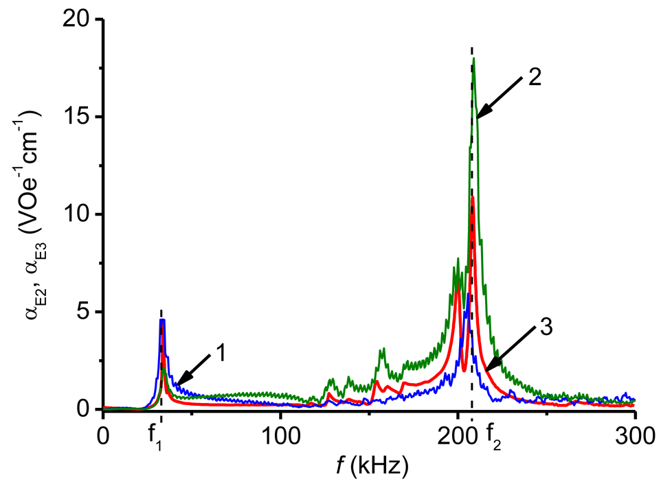
Finally, how the results of pulse measurements can be used to rapidly characterize a ME material must be demonstrated. The measured output voltage u(t) can be directly recalculated into the nonlinear ME coefficient:
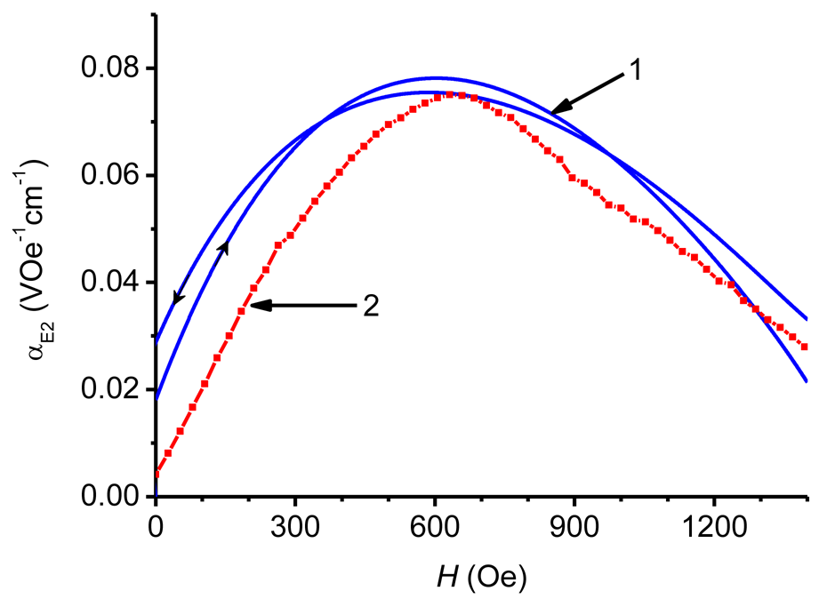
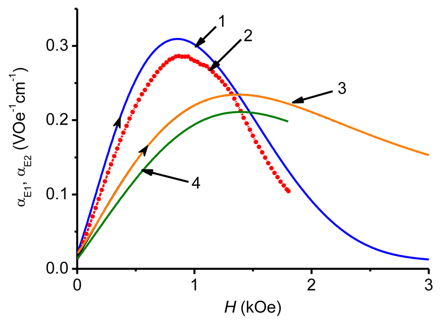
Indeed, the coefficient αE1(H) obtained from Equation (5) by the HFM method (Figure 7, curve 4) is in very good agreement with that measured by the pulse method (curve 3). For many applications, the frequency response αE2(f) is also of a great interest. Here Equation (4) also applies and the characteristics αE2(f) are usually measured at such a bias field Hm, where the piezomagnetic coefficient q(H) has its maximum value. At the given excitation frequency f the maximum of αE2(H) is observed at H = Hm. Figure 8 shows the dependence αE2(f) obtained with a bilayer CoFe/PZT structure by the HFM method at a bias field strength Hm = 650 Oe. The definition of αE2(f) used in the HFM method cannot be directly transferred to the pulse method, since there is no magnetic bias field applied. In [12] the following characterization methodology was proposed: use the measured time dependences of the field pulse H(t) and the voltage pulse u(t), find the frequency spectra of pulses h(f) and g(f) by means of the Fourier transform [27] and then calculate the frequency response αE3(f) from formula:
4. Conclusions
The peculiarities of the ME response of planar composite structures with FM (CoFe alloy or Ni) and PE (PZT) layers on magnetic-field pulses with a length of about 450 μs and amplitudes from 500 Oe to 38 kOe have been investigated.
It is found that when the amplitude of the field pulse exceeds the saturation field of magnetostriction in the FM layer (more than ≈ 1.5 kOe for the CoFe alloy and more than ≈ 0.5 kOe for Ni) there is a clipping of the amplitude of the generated pulse voltage. The time dependence of the generated voltage follows the time dependence of the magnetostriction in the FM material.
With further increase in pulse amplitude fields in the bilayer structures, first bending oscillations, leading to low-frequency modulation of the voltage pulse, are excited and then the planar acoustic oscillations, leading to high-frequency modulation of the voltage pulse, appear. In symmetric trilayer structures only high-frequency planar acoustic oscillations are efficiently excited with large amplitudes of the magnetic field pulse.
It is shown that the data of pulse measurements enables one to quickly find the frequency and field dependences of the efficiency of direct ME interaction in composite structures. Note that these dependences are obtained from a single measurement as compared to two separate measurements required in the HFM method.
The results obtained can be useful for developing ME sensors of pulsed magnetic fields. To extend the working field range of these sensors FM layers with high magnetostriction saturation field strength should be selected. The appearance of the oscillations of the generated voltage due to the excitation of acoustic oscillations in the structure may lead to limitations in dynamic range of such sensors.
Acknowledgments
Financial support by the International Bureau of the German Federal Ministry of Education and Research (Project RUS 10/016) is gratefully acknowledged. The research at MIREA was supported by the Ministry of Science and Education of Russian Federation and The Russian Foundation for Basic Research. The work in Regensburg was also supported by BayStMWIVT/European Union. The manufacturers of PE and FM materials are gratefully acknowledged for providing the free samples.
Appendix

| Symbol | Meaning | Unit |
|---|---|---|
| A | Cross sectional area of the sample | mm2 |
| a | Total thickness of the sample | mm |
| am | Thickness of the FM layer | mm |
| ap | Thickness of the PE layer | mm |
| b | Sample width | mm |
| d, dij | Piezoelectric coefficient | V−1·m |
| f1 | Frequency of bending oscillations | Hz |
| f2 | Frequency of planar oscillations | Hz |
| fS | Sampling frequency for discrete Fourier transform | Hz |
| Amplitude spectrum of the voltage pulse, f = k × fS × N−1 [27] | V | |
| g0= g(0) | V | |
| g1= g(f1) | V | |
| g2= g(f2) | V | |
| Amplitude spectrum of a rectangular pulse | Vs | |
| Amplitude spectrum of a half-sine pulse | Vs | |
| Magnetic field strength | Oe | |
| Hm | Magnetic field strength where q is maximum | Oe |
| HS | Saturation field of magnetostriction | Oe |
| Ĥ | Amplitude of the magnetic pulse | Oe |
| Amplitude spectrum of the magnetic pulse, f = k × fS × N−1 [27] | Oe | |
| I | Electric current | A |
| J | Cross sectional moment of inertia | m4 |
| j | j2 = −1 | - |
| L | Sample length | mm |
| N | Number of measurement points for Fourier transform | - |
| q | Piezomagnetic coefficient | Oe−1 |
| Q1 | Quality factor at f1 | - |
| Q2 | Quality factor at f2 | - |
| msij | Compliance coefficient of the FM layer | m2·N−1 |
| psij | Compliance coefficient of the PM layer | m2·N−1 |
| u | Generated ME voltage (see Figure 2) | V |
| u0 | Amplitude of voltage pulse without oscillations (see Figure 3) | V |
| u1 | Amplitude of voltage pulse at f1 (see Figure 3) | V |
| u2 | Amplitude of voltage pulse at f2 (see Figure 4) | V |
| ui | Induced voltage in the pick-up coil (see Figure 2) | V |
| v | Volume fraction of the PE phase | - |
| Y | Young's modulus | N·m−2 |
| αE1 | Nonlinear ME coefficient | V·Oe−1·cm−1 |
| αE2 | Linear ME coefficient | V·Oe−1·cm−1 |
| αE3 | ME coefficient according to [12] | V·Oe−1·cm−1 |
| εij | Effective permittivity | A·V−1·m−1·s |
| λ | Magnetostriction coefficient | - |
| λS | Saturation magnetostriction | - |
| ρm | Density of FM layer | kg·m−3 |
| ρp | Density of PE layer | kg·m−3 |
| τ | Pulse duration | s |
| μ | Poisson's ratio | - |
| μ0 | Vacuum permeability | H·m−1 |
References
- Nan, C.-W.; Bichurin, M.I.; Dong, S.; Viehland, D.; Srinivasan, G. Multiferroic magnetoelectric composites: Historical perspective, status, and future directions. J. Appl. Phys. 2008, 103, 142–149. [Google Scholar]
- Fetisov, Y.K.; Bush, A.A.; Kamentsev, K.E.; Ostashchenko, A.Y.; Srinivasan, G. Ferrite-piezoelectric multilayers for magnetic field sensors. IEEE Sens. J. 2006, 6, 935–938. [Google Scholar]
- Fiebig, M. Revival of the magnetoelectric effect. J. Phys. D-Appl. Phys. 2005, 38, R1–R30. [Google Scholar]
- Bichurin, M.I.; Filippov, D.A.; Petrov, V.M.; Laletsin, V.M.; Paddubnaya, N.; Srinivasan, G. Resonance magnetoelectric effects in layered magnetostrictive-piezoelectric composites. Phys. Rev. B 2003. [Google Scholar] [CrossRef]
- Zhai, J.Y.; Xing, Z.P.; Dong, S.X; Li, J.F.; Viehland, D. Detection of pico-tesla magnetic fields using magneto-electric sensors at room temperature. Appl. Phys. Lett. 2006, 88, 062510:1–062510:3. [Google Scholar]
- Dong, S.; Zhai, J.; Li, J.-F.; Viehland, D. Extremely low frequency response of magnetoelectric multilayer composites. Appl. Phys. Lett. 2005, 86, 102901:1–102901:3. [Google Scholar]
- Kamentsev, K.E.; Fetisov, Y.K.; Srinivasan, G. Ultra-low frequency magnetoelectric effect in a multilayer ferrite-piezoelectric structure. Tech. Phys. 2007, 52, 727–733. [Google Scholar]
- Jahns, R.; Greve, H.; Woltermann, E.; Quandt, E.; Knöchel, R.H. Noise performance of magnetometers with resonant thin-film magnetoelectric sensors. IEEE Trans. Instrum. Meas. 2011, 60, 2995–3001. [Google Scholar]
- Gao, J.; Shen, Y.; Wang, Y.; Finkel, P.; Viehland, D. Magnetoelectric bending-mode structure based on Metglas-Pb(Zr,Ti)O3 fiber laminates. IEEE Trans. Ultrason. Ferroel. Freq. Control 2011, 58, 1545–1549. [Google Scholar]
- Shen, L.; Li, M.; Gao, J.; Shen, Y.; Li, J.F.; Viehland, D.; Zhuang, X.; Lam, C.S.M.; Cordier, C.; Saez, S.; et al. Magnetoelectric nonlinearity in magnetoelectric laminate sensors. J. Appl. Phys. 2011, 110, 114510:1–114510:6. [Google Scholar]
- O'Dell, T.H. Pulse measurements of the magnetoelectric effect in chromium oxide. IEEE Trans. Magn. 1966, 2, 449–452. [Google Scholar]
- Ostashchenko, A.Y.; Kamentsev, K.E.; Fetisov, Y.K.; Srinivasan, G. Magnetoelectric response of a multilayer ferrite-piezoelectric structure to magnetic field pulses. Tech. Phys. Lett. 2004, 30, 769–771. [Google Scholar]
- Fetisov, Y.K.; Kamentsev, K.E.; Ostashchenko, A.Y.; Srinivasan, G. Wide-band characterization of a ferrite-piezoelectric multilayer using pulsed magnetic field. Solid State Commun. 2004, 64, 13–17. [Google Scholar]
- Bueno-Baques, D.; Grossinger, R.; Schonhart, M.; Doung, G.V.; Sato, R.; Corral-Flores, V.; Matutes-Aquino, J. The magnetoelectric effect in pulsed magnetic fields. J. Appl. Phys. 2006, 99, 08D908:1–08D908:3. [Google Scholar]
- Duong, G.V.; Turtelli, R.S.; Grossinger, R. Magnetoelectric properties of CoFe2O4-BaTiO3 structure composite studied by a magnetic pulse method. J. Magn. Magn. Mater. 2010, 332, 1581–1584. [Google Scholar]
- Wang, T.-Z.; Zhou, Y.-H. A theoretical study of nonlinear magnetoelectric effect in magnetostrictive-piezoelectric trilayer. Compos. Struct. 2011, 93, 1485–1492. [Google Scholar]
- Hörner, E.; Krykanov, I.M.; Chashin, D.V.; Fetisov, Y.K.; Fetisov, L.Y.; Shamonin, M. Magnetoelectric characteristics of cobalt-iron alloy-lead zirconate titanate bilayer planar structures. Int. J. Mat. Res. 2012. in press. [Google Scholar]
- Laletin, V.M.; Petrov, V.M. Nonlinear magnetoelectric response of a bulk magnetostrictive-piezoelectric composite. Solid State Commun. 2011, 151, 1806–1809. [Google Scholar]
- Fetisov, Y.K; Kamentsev, K.E.; Fetisov, L.Y.; Srinivasan, G. Frequency dependence of magnetoelectric voltage for a multilayer ferrite-piezoelectric structure with finite conductivity. Integr. Ferroelectr. 2009, 106, 23–28. [Google Scholar]
- Bichurin, M.I.; Petrov, V.M. Modeling of magnetoelectric interaction in magnetostrictive-piezoelectric composites. Adv. Cond. Mat. Phys. 2012. [Google Scholar] [CrossRef]
- Harshe, G.; Dougherty, J.P.; Newham, R.E. Theoretical modeling of multilayer magnetoelectric composites. Int. J. Appl. Electromagn. Mat. 1993, 4, 145–159. [Google Scholar]
- Vopsaroiu, M.; Blackburn, J.; Cain, M.C. A new magnetic recording head technology based on the magneto-electric effect. J. Phys. D-Appl. Phys. 2007, 40, 5027–5033. [Google Scholar]
- Petrov, V.M.; Srinivasan, G.; Bichurin, M.I.; Galkina, T.A. Theory of magnetoelectric effect for bending modes in magnetostrictive-piezoelectric bilayers. J. Appl. Phys. 2009, 105, 063911:1–063911:6. [Google Scholar]
- Wang, R.; Han, Q.; Pan, E. Transient response of a bi-layered multiferroic composite plate. Acta Mechanica Solida Sinica 2011, 24, 83–91. [Google Scholar]
- Liverts, E.; Grosz, A.; Zadov, B.; Bichurin, M.I.; Pukinskiy, Y.J.; Priya, S.; Viehland, D.; Paperno, E. Demagnetizing factors for two parallel ferromagnetic plates and their applications to magnetoelectric laminated sensors. J. Appl. Phys. 2011, 109, 07D703:1–07D703:3. [Google Scholar]
- Wang, Y.; Atulasimha, J.; Prasoon, R. Nonlinear magnetoelectric behavior of Terfenol-D/PZT-5A laminate composites. Smart Mater. Struct. 2010. [Google Scholar] [CrossRef]
- Press, W.H.; Teukolsky, S.A.; Vetterling, W.T.; Flannery, B.P. Numerical Recipes in C: The Art of Scientific Computing, 2nd ed.; Cambridge University Press: Cambridge, UK, 2002; pp. 496–608. [Google Scholar]


| Material | s11 (10−12 m2·N−1) | s12 (10−12 m2·N−1) | d31 (10−12 m·V−1) | ρ (103 kg·m−3) | λs (10−6) | ε33/ε0 |
|---|---|---|---|---|---|---|
| PZT | 14.20 | −3.7 | −315 | 8.1 | - | 4,500 |
| CoFe | 4.76 | −1.66 | - | 8.12 | 60 | - |
© 2012 by the authors; licensee MDPI, Basel, Switzerland. This article is an open access article distributed under the terms and conditions of the Creative Commons Attribution license (http://creativecommons.org/licenses/by/3.0/).
Share and Cite
Kreitmeier, F.; Chashin, D.V.; Fetisov, Y.K.; Fetisov, L.Y.; Schulz, I.; Monkman, G.J.; Shamonin, M. Nonlinear Magnetoelectric Response of Planar Ferromagnetic-Piezoelectric Structures to Sub-Millisecond Magnetic Pulses. Sensors 2012, 12, 14821-14837. https://doi.org/10.3390/s121114821
Kreitmeier F, Chashin DV, Fetisov YK, Fetisov LY, Schulz I, Monkman GJ, Shamonin M. Nonlinear Magnetoelectric Response of Planar Ferromagnetic-Piezoelectric Structures to Sub-Millisecond Magnetic Pulses. Sensors. 2012; 12(11):14821-14837. https://doi.org/10.3390/s121114821
Chicago/Turabian StyleKreitmeier, Florian, Dmitry V. Chashin, Yury K. Fetisov, Leonid Y. Fetisov, Irene Schulz, Gareth J. Monkman, and Mikhail Shamonin. 2012. "Nonlinear Magnetoelectric Response of Planar Ferromagnetic-Piezoelectric Structures to Sub-Millisecond Magnetic Pulses" Sensors 12, no. 11: 14821-14837. https://doi.org/10.3390/s121114821
APA StyleKreitmeier, F., Chashin, D. V., Fetisov, Y. K., Fetisov, L. Y., Schulz, I., Monkman, G. J., & Shamonin, M. (2012). Nonlinear Magnetoelectric Response of Planar Ferromagnetic-Piezoelectric Structures to Sub-Millisecond Magnetic Pulses. Sensors, 12(11), 14821-14837. https://doi.org/10.3390/s121114821