Article

Lanthanide Contraction in LnF3 (Ln = Ce-Lu) and Its Chemical and Structural Consequences: Part 1: Location of YF3 in the LnF3 Series According to Its Chemical and Structural Characteristics

by
Boris P. Sobolev
and
Elena A. Sulyanova
*
Shubnikov Institute of Crystallography, Federal Scientific Research Centre “Crystallography and Photonics”, Russian Academy of Sciences, Leninskiy Prospekt 59, 119333 Moscow, Russia
*
Author to whom correspondence should be addressed.
Int. J. Mol. Sci. 2023, 24(23), 17013; https://doi.org/10.3390/ijms242317013
Submission received: 24 October 2023 / Revised: 22 November 2023 / Accepted: 28 November 2023 / Published: 30 November 2023
(This article belongs to the Special Issue Recent Advances on Fluorine Chemistry)

Abstract

:
A lanthanide contraction (LC) of 14 lanthanides (Ln) from 58Ce to 71Lu consists of the interaction of Ln nucleus with 4f-electrons. Rare earth elements (REEs—R) include Sc, Y, La, and 14 Ln. They are located in 4–6th periods of the subgroup of group III. The electronic structure divides R into short (d- Sc, Y, La) and long (14 f-elements Ce-Lu) homologous series. The most important chemical consequence of LC is the creation of a new conglomerate of 16 RF3 by mixing fluorides of d- (Y, La) and f-elements. This determines the location of YF3 among LnF3. The location of YF3 depends on the structural (formula volumesVform) and thermochemical (temperatures and heats of phase transformations, phase diagrams) properties. The location of YF3 between HoF3 and ErF3 was determined by Vform at a standard pressure (Pst) and temperature (Tst). The location of YF3 according to heats of phase transformations ΔHfus and ΔHtrans is in a dimorphic structural subgroup (SSGr) D (Ln = Er-Lu), but without the exact “pseudo ZY”. According to the temperatures of phase transformations (Ttrans) in LnF3 (Ln = Dy-Lu), YF3 is located in the SSGr D between ErF3 and TmF3. The ErF3-YF3 and YF3-TmF3 phase diagrams show it to be between ErF3 and TmF3. The crystals of five β-LnF3 (Ln = Ho-Lu) and β-YF3 were obtained in identical conditions and their crystal structures were studied. Vform (at Pst and Tst) with “pseudoatomic number ZY = 67.42 was calculated from the unit cell parameters, which were defined with ±5 × 10⁻⁴ Å accuracy. It determines the location of YF3 between HoF3 and ErF3.

1. Introduction

This study opens up a series of investigations on LCs and their chemical and structural consequences in homologous series of LaF3 and 14 LnF3. The (La,Ln)F3 series differs from the homologous series of Ln compounds by characteristics that make it unique for the precise study of LCs. The formula for the (La,Ln)F3 series is simple. It determines the qualitative and quantitative chemical compositions that are favorable for the LC study. Fluorine anion has low atomic mass (19). High atomic masses of Ln lead at the beginning of the series in CeF3 to 71% and at the end of LuF3 to ~75% of the mass of compressible Ln3+. The LC in LnF3 has an extremely high “sensitivity” to volumetric changes when filling the 4f-orbital.
Despite the difference in the electronic structure, according to IUPAC recommendation, La is classified as Ln. This disadvantage of REE classification was noted by IUPAC as a project to clarify the location of La (2015). In this study, the formula (La,Ln)F3 is used when discussing issues related to LCs. This formula is not equivalent to a structural formula that isolates chemical elements in equivalent structural positions. The purpose of the (La,Ln) designation is to separate 14 Ln (4f-elements), which are exposed to a LC, from La, which has no f-electrons. When LC is not discussed, the R abbreviations for Y, La, and 14 Ln are used.
Owing to the extreme electronegativity of fluorine 4.0 according to [1] (after helium and neon), RF3 compounds have a high degree of a chemical bond ionicity; therefore, they are characterized by high melting points (Tfus). They crystallize from the melt in the form of large crystalline blocks, which are suitable for structural studies. All RF3 are chemically resistant, except SmF3, EuF3, and YbF3. They were subjected to partial reduction under the conditions of an experiment on crystal growth and the study of phase diagrams with their participation [2,3,4,5,6,7].
The location of YF3 in the LnF3 series is determined not by its Z = 39 but by the structural and chemical characteristics of 39YF3, independent of LC. Therefore, this location is ambiguous. According to the literature, the location of YF3 depends on its structural (unit cell parameters, formula volumes) or thermochemical (temperature, heat of phase transformation, phase diagrams) properties. In this study, a critical analysis of the structural and thermal characteristics of YF3 is performed according to the data of various research groups and our own precise structural data.
The term LC was first used in [8], and the name was given to the family of 14 Ln (“similar to lanthanum”). The Ln3+ ionic radius in REE oxides was chosen as a characteristic of LC. According to [8], the radius of R3+ (r+) decreases from La3+ to Lu3+ by ~15%. These data have been included in the educational literature and are still being cited. The radii were obtained on an incomplete REE series. Owing to the unresolved problem of REE separation in those years, the purity of some oxides by the main component had reached 50% at. Historically, r+ in R2O3 has become the first example of a comparative study of LC.
The compression of Ln3+ ions is expressed as an integral effect, that is, a change in the volume of a crystal. To compare non-cubic crystals, which are all RF3, it is convenient to express changes in the unit cell parameters using Vform. The ultimate goal of precise LC studies is to obtain the dependence of r+ on Z for Pst and Tst: rLn = f0(Z).
A change in the state parameter T > Tst causes structural changes in the RF3 series: polymorphic (PolTr) and morphotropic transformations. Both transformations proceed with abrupt changes in Vform. The RF3 PolTr exhibit a density anomaly. The high-temperature form is denser (usually opposite). Materials that expand after PolTr at heating are called materials with negative thermal expansion based on a phase transition-type mechanism [9]. Vform changes with Z according to different dependencies: for the LaF3 type (hereafter t-) by Vt- = f1(Z), and for the β-YF3 type (hereinafter β-) by Vβ- = f2(Z).
The difference in the electronic structure requires dividing the REE into short Sc, Y, La (d-elements), and long (14 f-elements) homologous series. In the short series, 21Sc→39Y→57La, r+ increases in group III in the ΔZ = 18 interval. In the long series, a LC phenomenon, which is unique to the periodic table of elements, is realized. The LC of the elements of period 6 (Ln = 58Ce-71Lu) is a result of an interaction in the “Ln nucleus—4f-electrons” atomic subsystem. The minimum “period” of the long series is ΔZ = 1. This corresponds to the transition between neighboring LnF3. At the same time, the size of Ln3+ cation decreases significantly with increasing Z due to LC.
d-REE La occupies a dual position. Having no f-electrons, La heads the Ln family, giving it a name. The IUPAC assignment of La to Ln is caused by the neighborhood of 57La in the 6th period with 58Ce at ΔZ = 1.
Yttrium has no f-electrons, and its r+ is independent of LC. The indirect effect of LC on the rapprochement of YF3 structural and chemical properties with LnF3 properties is due to the influence of LC on Ln3+. This is expressed as a decrease in r+ with an increase in Z.
The location of LaF3 at the beginning of the LnF3 series does not raise any questions. The Periodic Table of elements places it there by Z(La) = 57. This location before 58CeF3 is also justified by the structural and chemical proximity of LaF3 and CeF3 (ΔZ = 1).
A question arises about the location of YF3 in the LnF3 series. Unlike the unambiguous location of 57LaF3, the location of 39YF3 is determined not by its Z = 39, but by chemical and structural characteristics. The certainty of chemical characteristics is much less than the structural and absolute (Z) ones. In the literature there are several proposed locations of YF3.
The structural classification of 16 RF3 (without ScF3) homologous series and the chemical classification of the phase diagrams of 120 (without ScF3) RF3-R’F3 systems depend on the place of YF3 in the LnF3 series. The RF3 structural classification is the first level of a chemical classification of RF3-R’F3 systems.
To determine the location of YF3 in the LnF3 series, only precise information on LC in LnF3 is suitable. Two conditions ensure its receipt.
The first is the individuality of the homologous series of compounds. In this series of messages, for the first time, LC studies were performed on one (long) homologous series of REE fluorides: LaF3 and 14 LnF3. The high degree of bond ionicity and simple formula of the series give the absence of “blurring” of the boundaries of the change in structural types over the Ln series (for fixed P and T). This “blurring” accompanies all structural classifications of Ln compounds using their large arrays. The choice of compounds for arrays usually does not take into account differences in their chemical bonds. Arrays of compounds are heterogeneous in the chemical bonds. The conclusions of the most fundamental monograph [10] with an overview of 400 homologous series of REE compounds will be discussed in detail in the next message.
The general conclusion in [10] after processing a unique volume of data on LCs in the series of Ln compounds is categorical. “It is impossible to obtain an ideal system of REE ionic radii by averaging interatomic distances taken from a large number of structural definitions”. “Blurring” the several atomic numbers of the boundaries of “areas of crystal and chemical instability” [10] does not allow us to determine the subtle features of the LC evolution in the Ln series. These data are suitable neither for a precise study of the evolution of LC nor for constructing a specialized (Spec-zd) empirical (Emp) system of ionic radii (SIR) for RF3.
The second condition is the completeness of the LnF3 structural characteristics used to describe the changes in Vform during LC. The state of structural knowledge of RF3 is currently unsatisfactory both in terms of the number of studied compounds (about half) and in terms of the purity of the reagents used, especially in early works.
Structural studies of RF3 stretched over the years 1929–2023. During this period, significant changes occurred in the composition of RF3 crystals. It can be said that in the works of 30–70s, the purity of crystals by impurities of neighboring REE was not high. And only in 1971, YF3, LaF3, PrF3, NdF3, GdF3, HoF3, and LuF3 were published, with total REE content of 35–125 ppmw and with other cations content of 30–55 ppmw [11]. Cationic and anionic (oxygen) impurities are difficult to control. The structural data of RF3 distorted by them are unsuitable for precise studies of LC and the construction of the Spec-zd Emp SIR for (R,Ln)F3.
In this series of studies, the crystal structures of all members of the (R,Ln)F3 series are investigated. The structures of HoF3, ErF3, TmF3, YbF3, LuF3, and YF3 are discussed in the present study. The short quasi-system (QS) [12] “from HoF3 to LuF3” is used to obtain “pseudo ZY”. The location of YF3 is determined to be between HoF3 and ErF3 based on the value of Vform. The second message presents the structural data of t-RF3 with R = La-Nd of the LaF3 type, “pseudo t-SmF3”, and β-LnF3 (Ln = Sm-Dy) of the β-YF3 type. The empirical structural data obtained for cations and fluorine anion will become the basis for the Spec-zd Emp SIR for Y3+, La3+, and 14 Ln3+ for RF3.
The aim of this study is to clarify the most extensive indirect chemical consequence of LC, which is the location of fluoride of the d-element YF3 in a series of 4f-elements LnF3.

2. Results

2.1. Obtaining YF3 and LnF3 with Ln = Ho-Lu for Structural Studies

X-ray diffraction (XRD) analysis of YF3 and LnF3 with Ln = Ho-Lu was performed on the samples prepared using modern technology for the synthesis of crystals prone to pyrohydrolysis REE fluorides.
The RF3 reagents were prepared at the experimental plant (town Pyshma) of the Government Institute of Rare Metals (GIREDMET, Moscow, Russia). RF3 were melted and fluorinated to purify oxygen impurities. Oxygen content of 0.005–0.08 wt. % has been achieved (determination by vacuum melting) [13,14]. Differential thermal analysis used for the study of phase diagrams provided control over the oxygen impurity content in RF3 (in the form of an isomorphic admixture of RF3−2xOx oxyfluorides) at an acceptable level [15].
The purity of the reagents by the main component was 99.9 wt. %. Each reagent was certified for REE impurities based on X-ray fluorescence analysis. The typical impurity composition of YF3 produced by Pyshma, according to [16], is listed in Table 1.
After fluorination, the samples consisted of large crystalline blocks suitable for structural analysis.

2.2. X-ray Diffraction Study of β-YF3 and Five β-LnF3 (Ln = Ho-Lu)

To accurately determine the position of YF3 in the LnF3 series using structural characteristics the structures of β-YF3 and five β-LnF3 (Ln = Ho-Lu) were studied.
XRD study were performed using modern equipment for structural analysis under comparable experimental conditions. Only the combination of these factors, which were absent earlier when creating universal (Univ) SIRs, provides high accuracy in describing the evolution of LC in the LnF3 series and calculating comparable values of r+ for the Spec-zd Emp SIR for RF3.
Single crystal XRD study of β-YF3 and β-LnF3 (Ln = Ho-Lu) was performed at 293 K using an XtaLAB Synergy-DW (Rigaku Oxford Diffraction, Japan-UK-Poland) diffractometer with an Ag-anode X-ray tube. The data were processed using the CrysAlisPro version 171.42.72 (Rigaku Oxford Diffraction, Japan-UK-Poland) software package.
Powder XRD analysis was performed at 293 K with a Rigaku MiniFlex 600 Bragg-Brentano diffractometer using a Cu-anode X-ray tube within the range of 2θ = 10–100° and with a 2θ step size of 0.02°. A NIST 640e standard (Si) sample was added to the sample to determine the 2θ correction. The details of the XRD experiments are listed in Table 2.
The JANA2020 program [17] was used for the structure solution and refinement. The structures were refined within Pnma sp. gr. An isotropic extinction correction was introduced into the fitted models according to the Becker–Coppens formalism [18]. The Wickoff positions (W.p.) [19], coordinates, site occupancy factors, and equivalent atomic displacement parameters for β-YF3 and β-LnF3 (Ln = Ho-Lu) at 293 K are listed in Table 3.

3. Discussion

3.1. Determination of “Pseudo ZY” According to Literature Data

The first group of structural properties is the type of structure and unit cell parameters. The most precise (±0.0005 Å) measurements of the RF3 unit cell parameters in a Guinier chamber were used [11,20]. The YF3 unit cell parameters [11] differs from that of [20]. The reason for this difference is unknown.
The second group includes the thermal properties: the temperatures (Tfus) and enthalpies ΔHfus of melting and Ttrans and ΔHtrans of the PolTrs. These characteristics determine the location of YF3 in the LnF3 series for condensed systems with Pst and Tst. The condensed (at Pst) single-component (Z = const) systems include YF3, LaF3, and all LnF3 except volatile (at heating) ScF3 [21,22]. In such systems, PolTr is invariant and proceeds “at a point” T = Ttrans = const.
The Ttrans were taken from a review [23] as the average of those published before 2003 for fluorides of f-elements. There is no Ttrans for YF3 among them.
ΔHfus and ΔHtrans for all RF3 were cited from the fundamental research of one group of authors [11,24]. Synthesis and analysis of the basic and impurity RF3 compositions and purification from oxygen (control by analysis) were performed at Iowa State University, USA.
Phase diagrams of the two-component RF3-R’F3 systems were used for the first time to clarify the location of YF3. These systems were studied by one group [25]. The phase diagrams of the RF3-R’F3 systems contain data on the Ttrans of the components. The location of YF3 in the short QS [12] depends on the thermal properties of the LnF3 components that form this QS.

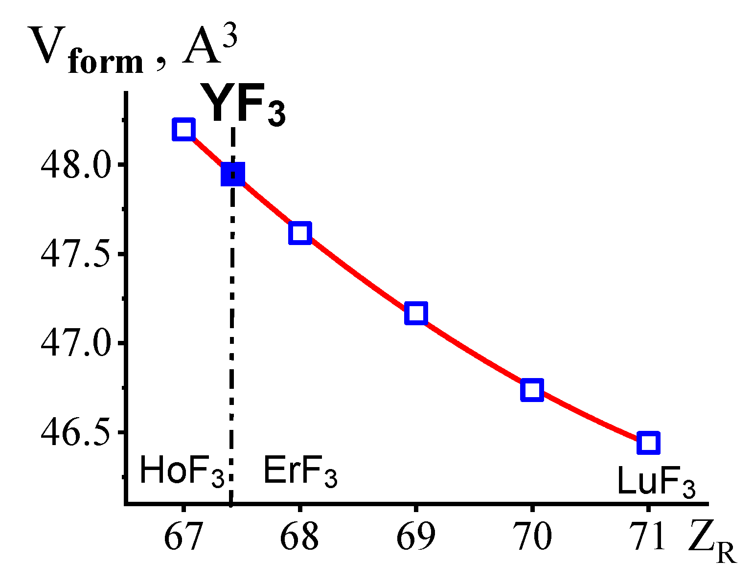
3.2. Location of YF3 in the LnF3 Series in Terms of the Structural Types and Unit Cell Parameters of 16 RF3 (without ScF3) at Pst and Tst

The generally accepted scheme for the change of Ttrans and crystal structures of 17 RF3 was formed by the mid-80s of the last century by three scientific groups: the USA, Russia, and Germany. However, six outdated schemes were also cited. This forces us to repeat up-to-date ideas about RF3 structures.
At T < Tfus RF3 crystallize in four structural types: (1) ScF3 (ReO3 type), (2) β-YF3 (β-), (3) LaF3 (t-), and (4) α-YF3 (α-). The α-type is stable close to its melting point and was observed in situ only.
The structural classification of RF3 (without ScF3) based on the type of structure and presence (absence) of polymorphism is presented in Table 4. Four SSGr were allocated. The members of the SSGr A (LaF3, CeF3, PrF3, and NdF3) and C (TbF3, DyF3, and HoF3) are monomorphic and have t- and β- structural types up to the melting point, respectively. The members of the dimorphic SSGr B—PmF3, SmF3, EuF3, and GdF3—have t- (high-temperature) and β- (low-temperature) structural types. The members of the dimorphic SSGr D (ErF3, TmF3, YbF3, and LuF3) have α- (high temperature) and β- (low temperature) structural types.
The β-YF3 unit cell parameters according to [11,20,24,26] together with Vforms calculated from them at Tst and Pst are listed in Table 5. In the right column, the LnF3-Ln’F3 systems are provided, in which Vform of YF3 is located between the Vforms of components.
The Vforms of YF3 according to [11,26] are close to each other. They locate YF3 between HoF3 and ErF3. According to [20] YF3 is located between DyF3 and HoF3. This is contradicted by the only form of β- in both fluorides before Tfus. These data were excluded.

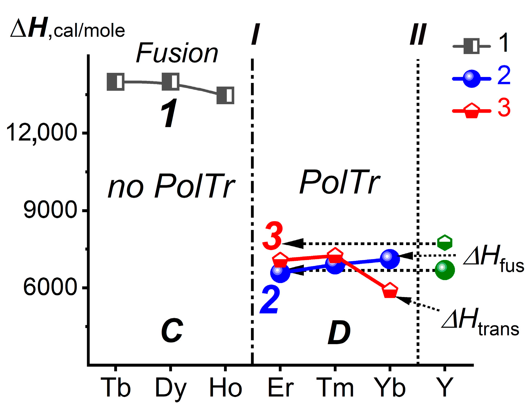
3.3. Location of YF3 in the LnF3 Series in Terms of Tfus and ΔHtrans

A review of Ttrans in (La,Ln)F3 (without ScF3 andYF3) was done [23]. The Ttrans for each (La,Ln)F3 was obtained with an accuracy of ±3 °C. The limitation [23] is in the exclusion of YF3 from the list as a fluoride of d-element. For YF3, we adopted Ttrans from [11].
The blue solid circles in Figure 1 show the Tfus (curve 1) and red open rectangles (curve 2) Ttrans of LnF3 in the short QS “from DyF3 to LuF3”. The fields of structural modifications are designated as β- and α-. The border between C and D SSGrs is marked with a dash-dotted vertical I.
The Tfus and Ttrans of YF3 are shown by green semi-open icons. These are separated from the data for LnF3 series by vertical II. The arrows to the left of these points intersect curves 1 and 2 near Z = 69, corresponding to 69Tm. The intersections are shown as Y-vertical. According to Ttrans in LnF3 (Ln = Dy-Lu) [23], YF3 is located between ErF3 and TmF3. This is consistent with the location of YF3 in the SSGr D.
The ΔHfus for LnF3 with Ln = Tb-Yb are shown in Figure 2 by curves 1 (grey semi-open rectangles) and 2 (blue solid circles). Curve 3 (red semi-open rhombs) corresponds to ΔHtrans for LnF3 of the dimorphic SSGr D (ErF3-YbF3) at Pst [11,24].
The ΔHfus and ΔHtrans of dimorphic YF3 are shown in Figure 2 by green icons. The values of the ΔHfus and ΔHtrans of YF3 are projected into the Z region corresponding to ErF3 without intersecting curves 2 and 3, respectively. According to ΔHfus and ΔHtrans, YF3 is located in the SSGr D. However, the location of YF3 cannot be precisely determined because of the proximity of the ΔH values. Despite the high accuracy of thermophysical measurements [11,24], they do not contain strict information regarding the location of YF3.

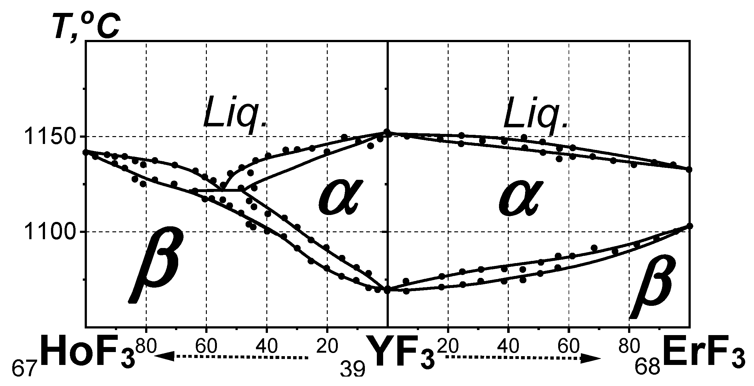
3.4. Location of YF3 Based on the YF3-LnF3 Phase Diagrams at P = Pst, T > Tst

The possible location of YF3 on the basis of phase diagrams was obtained based on the location of YF3 between HoF3 and ErF3 determined from unit cell parameters and Vforms. The composite short “HoF3-YF3-ErF3” QS, including these fluorides (Figure 3), was analyzed.
The phase diagrams of the HoF3-YF3 and YF3-ErF3 systems [25] are not included in the full “from LaF3 to LuF3” QS [12]. The short “HoF3-YF3-ErF3” QS is called composite to emphasize the violation of the ΔZ = 1 condition for (R,Ln)F3 sequence in the true QS by “inserting” a component— a fluoride of the d-element Y. The “inserted” 39YF3 connects the 67HoF3 and 68ErF3 components of the full QS with continuous lines of liquidus and solidus into the short composite “HoF3-YF3-ErF3” QS.
If the location of dimorphic YF3 is in the short composite “HoF3-YF3-ErF3” QS with monomorphic HoF3, its Tfus = 1155 °C and Ttrans = 1077 °C [11] should be between that of ErF3 (Tfus = 1146 °C and Ttrans = 1117 °C [24]). But Tfus of YF3 is higher and Ttrans is lower than these of ErF3 (Figure 3). Thus, the location of YF3 in the phase diagram of the short composite “HoF3-YF3-ErF3” QS cannot be between HoF3 and ErF3.

3.5. Location of YF3 Based on the Phase Diagrams of the YF3-LnF3 Systems in the Short Composite “ErF3-YF3-TmF3” QS at P = Pst, T > Tst

The next possible QS for analyzing the location of YF3 is the short composite “ErF3-YF3-TmF3” QS, which is shown in Figure 4. It consists of the ErF3-YF3 and YF3-TmF3 systems.
The Ttrans of YF3 (1077 °C) is higher than that of TmF3 (1053 °C). At the same time, the Tfus values of both fluorides are almost identical (1155 and 1158 °C). They have the same types of structures (β- and α-).
The location of YF3 in the phase diagram of the short composite “ErF3-YF3-TmF3” QS is between ErF3 and TmF3. This corresponds to the location of YF3 based on its polymorphism and the structure of modifications.
From the literature data concerning the location of YF3 in the LnF3 series the following statements were obtained:
(1)
Structural data are not available for the entire (R,Ln)F3 series. These data are not sufficient for precise analysis of LC and determination of “pseudo ZY” of YF3.
(2)
Structural changes in large arrays of REE compounds of different homologous series with different chemical bonds exhibit uncontrolled shifts in the areas of change in the type of structure along the Z-axis. These data are unsuitable for precise studies of LC.
(3)
The thermal and thermochemical properties and phase diagrams are related to the common property—Ttrans. This common property determines the location of YF3 between ErF3 and TmF3, which is shifted by Z = 1 compared to the location based on Vform. The reason for this shift remains unknown.
(4)
The phase diagrams of the short composite “HoF3-YF3-ErF3” QS and the particular HoF3-ErF3 system do not confirm the location of YF3 between HoF3 and ErF3.
(5)
In the short composite “ErF3-YF3-TmF3” QS, YF3 is located between ErF3 and TmF3.
(6)
To analyze the subtle features of the LC evolution in the LnF3 series and obtain Spec-zd Emp SIR for (R,Ln)F3, the structural properties of all REE trifluorides obtained under the same technological conditions are required.

3.6. Definition of “Pseudo ZY” Using X-ray Diffraction Data

The integer value Z = 39 does not determine the 39YF3 location (“pseudo ZY”) in the LnF3 series. This can be determined by calculating Vform from the 39YF3 unit cell parameters and obtaining “pseudo ZY” by the equation Vform = f2(Z). “Pseudo ZY” corresponds to the exact place of 39YF3 in the LnF3 series in terms of its structural properties.
The Vforms were calculated from the β-YF3 and β-LnF3 (Ln = Ho-Lu) unit cell parameters (Table 2). In Figure 5, the open blue rectangles indicate the change in Vform in the β-LnF3 (Ln = Ho-Lu) series. The Vform of β-YF3 is indicated by the solid blue rectangle.
The Vform = f2(Z) curve is well approximated by a second-degree polynomial (red curve in Figure 5):
Vform = f2(Z) = 0.0419·Z2 − 6.22156·Z + 276.9491.
Vform = 47.948 Å3 of YF3 determined from this equation corresponds to “pseudo ZY” = 67.42. In the particular HoF3-ErF3 system this fractional Z value corresponds to the (Ho0.58Er0.42)F3 composition. This is close to the composition of the particular HoF3-ErF3 system with the morphotropic β- to α- structural change according to the eutectic phase reaction:
Liq ↔ β-(Ho0.64Er0.36)F3 + α-(Ho0.33Er0.66)F3
The occurrence of “pseudo ZY” in the region of the equilibrium existence of β-type solid solutions in the HoF3-ErF3 system indicates that YF3 belongs to the SSGr C. This contradicts the well-studied dimorphism of YF3 [27] and its affiliation with the SSGr D.
The differences in the YF3 location among LnF3 are related to the groups of properties by which this location is determined: structural and thermophysical. It can be assumed that they reflect the contributions of different natures to the total amount of LC.
The separation of the LC contribution (inside the “Ln nucleus—4f electrons” atomic subsystem) from the LnF3 volume changes as a result of polymorphic (morphotropic) changes in the type and density of the structure requires further study and discussion.
The precise determination of the 39YF3 location in the LnF3 series from the structural data (Vform) showed that it is located between HoF3 and ErF3 with “pseudo ZY” = 67.42.
Structural characteristics are used for precise study of LC in the LnF3 series and the volume changes caused by it. Therefore, they were chosen as defining the location of YF3 between HoF3 and ErF3.

4. Conclusions

LC of 14 Ln3+ from 58Ce3+ to 71Lu3+ consists of the interaction in the internal “Ln nucleus—4f-electrons” atomic subsystem. The REEs include Sc, Y, La and 14 Ln. They are located in 4–6th periods of the subgroup of group III. The electronic structure of R distinguishes the short (d- Sc, Y, La) and long (14 f-elements Ln = Ce-Lu) series.
The first chemical consequence of LC is the generation of the new conglomerate of 16 RF3 by mixing fluorides of 2 d- (Y, La) and 14 f-elements. Its creation is based on the structural and chemical proximity of members of the short and long RF3 series. Thus, LC indirectly determines the location of YF3 in the LnF3 series.
In the series of REE compounds with different types of chemical bonds, the shift of the yttrium compounds site is known, explicable, and natural. However, according to studies of different LnF3 properties, the location of YF3 may differ. Such differences can be caused by the differences in chemical bonds in different homologous series and by experimental errors that differ in different methods.
The location of YF3 in the LnF3 series depends on two groups of properties: structural (unit cell parameters and Vforms) and thermochemical (temperatures and heats of phase transformation, phase diagrams).
For precise structural characterization, crystals of β-YF3 and five β-LnF3 (Ln = Ho–Lu) were obtained and studied. Vforms (at Pst and Tst) calculated from the unit cell parameters determine the location of YF3 between HoF3 and ErF3.
According to ΔHfus and ΔHtrans, YF3 is located in the LnF3 dimorphic SSGr D (Ln = Er-Lu). ΔHfus and ΔHtrans cannot provide a more precise position of YF3 inside the SSGr D because they are close to each other.
According to Ttrans, YF3 is located between ErF3 and TmF3. This differs by +1 from its location which was determined based on Vforms. Simultaneously, this location does not contradict PolTrs and belonging of YF3 to the SSGr D of LnF3.
The phase diagrams of the short composite “HoF3-YF3-ErF3” and “ErF3-YF3-TmF3” QS and the particular HoF3-ErF3 system were applied for the first time to determine the location of YF3 in the LnF3 series. The phase diagrams are included in the group of thermal properties because they contain Tfus and Ttrans. The phase diagrams locate YF3 between ErF3 and TmF3.
To determine the location of YF3, the structures of β-YF3 and five β-LnF3 (Ln = Ho-Lu) were studied at 293 K, and their Vforms were calculated. In the short “from HoF3 to LuF3” QS using Vform = 47.948 Å3 the location of YF3 was determined between HoF3 and ErF3 with “pseudo ZY” = 67.42.

Author Contributions

B.P.S. is contributed to conceptualization, phase diagrams investigation, data analysis and interpretation, and writing of the published work. E.A.S. is contributed to X-ray diffraction experiments, structure solution and refinement, data analysis and interpretation, and writing of the published work. All authors have read and agreed to the published version of the manuscript.

Funding

This work was performed within the State Assignment of FSRC “Crystallography and Photonics” RAS.

Institutional Review Board Statement

Not applicable.

Informed Consent Statement

Not applicable.

Data Availability Statement

The data presented in this study are available on request from the corresponding author. The data on the crystal structures are deposited in the Cambridge Structural Database (CSD nums. 2254323, 2254302, 2254320, 2254321, 2254415, 2254322).

Acknowledgments

Authors are grateful to P.V. Kostoglodov for useful discussion and K.K. Rivkina for obtaining the high-purity REE trifluorides.

Conflicts of Interest

The authors declare no conflict of interest.

References

  1. Tantardini, C.; Oganov, A.R. Thermochemical electronegativities of the elements. Nat. Comm. 2021, 12, 20872087. [Google Scholar] [CrossRef]
  2. Greis, O.; Haschke, J.M. Rare Earth Fluorides. In Handbook on the Physics and Chemistry of Rare Earths; Gscheidner, K.A., Eyring, L.R., Eds.; Elsevier (North Holland Publishing Co.): Amsterdam, The Netherlands, 1982; Volume 5, pp. 387–460. [Google Scholar]
  3. Greis, O. Uber neue Verbindungen im System SmF2–SmF3. J. Solid State Chem. 1978, 24, 227–232. [Google Scholar] [CrossRef]
  4. Greis, O. Uber neue Verbindungen in den Systemen EuF2–EuF3 und SrF2–EuF3. Z. Anorgan. Allgem. Chem. 1978, 441, 39–46. [Google Scholar] [CrossRef]
  5. Karapetian, F.S.; Adamyan, V.E.; Arutunian, M.A.; Seiranian, K.B.; Grigorian, P.A.; Butaev, A.G. Temperature dependence of magnetic susceptibility and X-ray phase analysis of the system SrF2–EuF3. Izv. Akad. Nauk. SSSR Seriya Fiz. 1974, 9, 338–341. (In Russian) [Google Scholar]
  6. Greis, O. Phasenuntersuchungen am System YbF2–YbF3. Z. Anorgan. Allgem. Chem. 1977, 430, 175–198. [Google Scholar] [CrossRef]
  7. Petzel, T.; Greis, O. The evaporation behaviour of ytterbium (III) fluoride and ytterbium (II) fluoride. J. Less Common Metals. 1976, 46, 197–207. [Google Scholar] [CrossRef]
  8. Goldschmidt, V.M.; Barth, T.; Lunde, G.; Zachariasen, W. Geochemische Verteilungsgesetze der Elemente. Part V. Isomorphie und Polymorphie der Sesquioxyde. Die Lanthaniden-Kontraktion und Ihre Konsequenzen; Jacob Dybwad; Kristiania: Oslo, Norway, 1926; Volume 7, pp. 1–117. [Google Scholar]
  9. Takenaka, K. Progress of Research in Negative Thermal Expansion Materials: Paradigm Shift in the Control of Thermal Expansion. Front. Chem. 2018, 6, 267. [Google Scholar] [CrossRef]
  10. Bandurkin, G.A.; Dzhurinskii, B.F.; Tananaev, I.V. Features of Crystal Chemistry of REE Compounds; Nauka: Moscow, Russia, 1984; 230p. (In Russian) [Google Scholar]
  11. Spedding, F.H.; Henderson, D.C. High-temperature heat contents and related thermodynamic functions of seven trifluorides of the rare earths: Y, La, Pr, Nd, Gd, Ho, and Lu. J. Chem. Phys. 1971, 54, 2476–2483. [Google Scholar] [CrossRef]
  12. Sobolev, B.P. Full quasi-system “from LaF3 to LuF3” as a combination of 14 binary systems of lanthanide trifluorides with maximal chemical proximity. J. Solid State Chem. 2022, 312, 123164. [Google Scholar] [CrossRef]
  13. Glavin, G.G.; Karpov, Y.A.; Olzhataev, B.A. Oxygen determination in Y, Sr, Ca and Li fluorides by isotope dilution method. Zavod. Lab. Diagn. Mater. 1969, 35, 172–175. (In Russian) [Google Scholar]
  14. Glavin, G.G.; Karpov, Y.A. Oxygen determination in metallic RE and their fluorides. Zavod. Lab. Diagn. Mater. 1964, 30, 306–308. (In Russian) [Google Scholar]
  15. Sobolev, B.P.; Fedorov, P.P.; Steinberg, D.V.; Sinitsyn, B.V.; Shakhalamian, G.S. On the problem of polymorphism and fusion of lanthanide trifluorides. I. The influence of oxygen on phase transition temperatures. J. Solid State Chem. 1976, 17, 191–199. [Google Scholar] [CrossRef]
  16. Fedorov, P.P.; Alexandrov, V.B.; Bondareva, O.S.; Buchinskaya, I.I.; Val’kovskii, M.D.; Sobolev, B.P. Concentration dependence of cell parameters of Na0.5-xR0.5+xF2+2x fluorite phases. Crystallogr. Rep. 2001, 46, 280–286. (In Russian) [Google Scholar]
  17. Petricek, V.; Dusek, M.; Palatinus, L. Crystallographic computing system Jana2006: General features. Z. Kristallogr. 2014, 229, 345. [Google Scholar] [CrossRef]
  18. Becker, P.J.; Coppens, P. Extinction within the limit of validity of the Darwin transfer equations. I. General formalism for primary and secondary extinction and their applications to spherical crystals. Acta Cryst. A 1974, 30, 129–147. [Google Scholar] [CrossRef]
  19. Wyckoff, R.W.G. The Analytical Expression of the Results of the Theory of Space-Groups; Carnegie Institution of Washington: Washington, DA, USA, 1922; 180p. [Google Scholar]
  20. Greis, O.; Petzel, T. Ein Beitrag zur Strukturchemie eder Seltenerd-Trifluoride. Z. Anorgan. Allgem. Chem. 1974, 403, 1–22. [Google Scholar] [CrossRef]
  21. Kent, R.A.; Zmbov, K.E.; Kanan, A.S.; Besenbruch, G.; McDonald, J.D.; Margrave, J.L. Mass spectrometric studies at high temperatures. The sublimation pressures of scandium (III), yttrium (III) and lanthanum (III), trifluorides. J. Inorg. Nucl. Chem. 1966, 28, 1419–1427. [Google Scholar] [CrossRef]
  22. Rinehart, G.H.; Behrens, R.G. Vapour pressure and vaporization thermodynamics of ScF3. J. Less Common Metals. 1980, 75, 65–78. [Google Scholar] [CrossRef]
  23. Konings, R.J.M.; Kovacs, A. Handbook on the Physics and Chemistry of Rare Earths; Elsevier: Oxford, UK; Amsterdam, The Netherlands; New York, NY, USA, 2003; Volume 33, 147p. [Google Scholar]
  24. Spedding, F.H.; Beaudry, B.J.; Henderson, D.C.; Moorman, J. High temperature enthalpies and related thermodynamic functions of the trifluorides of Sc, Ce, Sm, Eu, Gd, Tb, Dy, Er, Tm, and Yb. J. Chem. Phys. 1974, 60, 1578–1588. [Google Scholar] [CrossRef]
  25. Sobolev, B.P. The Rare Earth Trifluorides, Part 1: The High Temperature Chemistry of the Rare Earth Trifluorides; Institute of Crystallography: Moscow, Russia; Institut d’Estudis Catalans: Barcelona, Spain, 2000; 520p. [Google Scholar]
  26. Zalkin, A.; Templeton, D.H. The crystal structures of YF3 and related compounds. J. Amer. Chem. Soc. 1953, 75, 2453–2458. [Google Scholar] [CrossRef]
  27. Greis, O.; Cader, M.S.R. Polymorphism of high purity rare earth trifluorides. Thermochim. Acta 1985, 87, 145–150. [Google Scholar] [CrossRef]
Figure 1. The location of YF3 in the LnF3 series based on the average Tfus (1), Ttrans (2) of LnF3 with Ln = Dy-Lu and YF3 (3, 4). Curve 1—Tfus of LnF3 with Ln = Dy-Lu (blue solid circles), curve 2—Ttrans of LnF3 with Ln = Er-Lu (red open rectangles). The Tfus (3) and Ttrans (4) of YF3 are shown by green semi-open icons. Vertical I is the boundary between structural subgroups C (Ln = Tb-Ho) and D (Ln = Er-Lu). Vertical II separates 39Y from the Z-scale for Ln.
Ijms 24 17013 g001
Figure 2. ΔHfus and ΔHtrans for LnF3 (Ln = Tb-Yb) and YF3. Curve 1—ΔHfus for LnF3 with Ln=Tb-Ho (grey semi-open rectangles), curve 2—ΔHfus for LnF3 with Ln = Er-Yb (blue solid circles), curve 3—ΔHtrans for LnF3 with Ln = Er-Yb (red semi-open rhombs). ΔHfus and ΔHtrans of YF3 are shown by green icons. Vertical I is the boundary between structural subgroups C (Ln = Tb-Ho) and D (Ln = Er-Lu). Vertical II separates 39Y from the Z-scale for Ln.
Ijms 24 17013 g002
Figure 3. The phase diagram of the short composite “HoF3-YF3-ErF3” QS (P = Pst; T > Tst). Black solid circles correspond to experimental data.
Ijms 24 17013 g003
Figure 4. The phase diagram of the short composite “ErF3-YF3-TmF3” QS (P = Pst, T > Tst). Black solid circles correspond to experimental data.
Ijms 24 17013 g004
Figure 5. The location of YF3 in the LnF3 (Ln = Ho-Lu) series based on Vform. Open blue rectangles—Vforms of β-LnF3 (Ln = Ho-Lu), the solid blue rectangles correspond to Vform of β-YF3.
Ijms 24 17013 g005
Table 1. Impurity composition of the YF3 samples produced by Pyshma, wt. %.
Nd<0.0005Dy0.0002Si<0.001Tm0.0005
Sm0.0002Ho<0.001Mn<0.00005Fe0.0005
Gd0.0005Cu<0.0005Co<0.00005Ti<0.00005
Tb0.0001O270 ppmwNi0.00005Cr0.00005
Table 2. Experimental crystallographic characteristics and results of the structure refinement for β-YF3 and β-LnF3 (Ln = Ho-Lu) at 293 K (this study).
RF3β-YF3β-HoF3β-ErF3β-TmF3β-YbF3β-LuF3
ICSD ID225432322543022254320225432122544152254322
Crystal systemOrthorhombic
Sp.gr., ZPnma, 6
a (Å)6.3666 (2)6.4055 (2)6.3500 (5)6.2792 (3)6.2168 (3)6.1437 (4)
b (Å)6.8579 (3)6.8739 (3)6.8435 (7)6.8141 (3)6.7852 (3)6.7606 (3)
c (Å)4.3927 (1)4.3784 (2)4.3829 (4)4.4095 (3)4.4318 (2)4.4724 (3)
V (Å 3)191.79 (1)192.78 (1)190.46 (3)188.67 (2)186.94 (2)185.76 (2)
Vform47.94848.19547.61547.16846.73546.440
Dx (g·cm−3)5.05287.64647.82057.95388.17328.2942
μ (mm−1)16.44121.75123.48624.98126.7128.387
Tmin, Tmax0.0891, 0.18780.0594, 0.15640.0391, 0.13120.0628, 0.16050.0222, 0.10510.0211, 01031
Shape, colorcolorlesslight yellowlight rosecolorlesscolorlesscolorless
Diameter (mm)0.20
Wavelength (Å)0.56087
Θ range (deg)4.35–72.654.36–72.854.36–72.784.34–73.034.33–72.824.31–72.87
Refl. collected19,37620,34920,52219,40319,99319,644
Refl. unique/Rint3573/4.553800/5.143342/5.003301/5.063333/4.652895/5.15
Refin. methodFull matrix least squares on F
Param/Restrains2338/038/038/038/066/0
R/wR, %2.26/3.702.38/3.932.05/3.102.60/4.012.80/4.112.51/3.39
Δρmin/Δρmax, Å−3−2.70/1.48−4.48/4.39−4.29/3.64−4.54/2.84−4.60/3.64−4.26/3.87
GOF1.361.471.431.401.621.39
Table 3. The Wyckoff positions (W.p.), site occupancy factors (s.o.f.), fractional coordinates, and equivalent thermal displacement parameters of atoms in β-YF3 and β-LnF3 (Ln = Ho-Lu) at 293 K.
RF3IonW.p.s.o.f.x/ay/bz/cUeq
YF3Y4c10.367845(12)¼0.05981(2)0.005423(11)
F(1)4c10.52302(15)¼0.5901(2)0.00976(12)
F(2)8b10.16454(10)0.06335(8)0.37686(16)0.00856(7)
HoF3Ho4c10.36809(3)¼0.06137(4)0.00483(5)
F(1)4c10.5217(2)¼0.5870(3)0.00925(16)
F(2)8b10.16429(16)0.06318(16)0.3803(2)0.00866(10)
ErF3Er4c10.36802(3)¼0.06027(4)0.00521(4)
F(1)4c10.5231(2)¼0.5909(3)0.00967(14)
F(2)8b10.16486(14)0.06248(12)0.37654(17)0.00871(9)
TmF3Tm4c10.36725(3)¼0.05609(4)0.00477(4)
F(1)4c10.5252(2)¼0.5971(5)0.0103(2)
F(2)8b10.16454(16)0.06304(15)0.3716(3)0.00867(12)
YbF3Yb4c10.36718(3)¼0.05395(5)0.00577(5)
F(1)4c10.5264(3)¼0.6017(4)0.0114(2)
F(2)8b10.16510(16)0.06231(14)0.3681(2)0.00897(12)
LuF3Lu4c10.36689(7)¼0.05044(10)0.00759(17)
F(1)4c10.5278(3)¼0.6056(4)0.0110(2)
F(2)8b10.16448(18)0.06265(13)0.3634(3)0.00951(11)
Table 4. The SSGrs AD of RF3.
SSGrsRF3RF3 Structural Types
ALaF3, CeF3, PrF3, and NdF3 monomorphict-
BPmF3, SmF3, EuF3, and GdF3 dimorphic(1) t- high-temperature
(2) β- low-temperature
CTbF3, DyF3, and HoF3 monomorphicβ-
DErF3, TmF3, YbF3, and LuF3 dimorphic(1) α- high-temperature
(2) β- low-temperature
Table 5. The location of β-YF3 in the LnF3 series based on Vform (literature data).
ReferenceUnit Cell Parameters, ÅVform
(Tst, Pst)
YF3 Location
abc
1953 Zalkin [26]6.3536.8504.39347.79between HoF3 and ErF3
1971 Spedding [11]6.3676.8594.39447.97between HoF3 and ErF3
1974 Greis [20]6.40276.88434.398048.46between DyF3 and HoF3
Disclaimer/Publisher’s Note: The statements, opinions and data contained in all publications are solely those of the individual author(s) and contributor(s) and not of MDPI and/or the editor(s). MDPI and/or the editor(s) disclaim responsibility for any injury to people or property resulting from any ideas, methods, instructions or products referred to in the content.

